1. Introduction
The thermal battery is a type of high-temperature battery with solid molten salt as the electrolyte [
1,
2,
3]. When in use, the internal fireworks source heats the battery stack to the working temperature for discharge [
1]. Thermal batteries have the advantages of a high power density, strong environmental adaptability, long storage life, and easy installation and maintenance and they are widely applied in weapons and equipment systems [
4], such as strategic and tactical missiles, torpedoes, guided bombs, nuclear weapons, and other emergency fields [
5,
6]. Due to the separation from a ground power supply, the system power supply of long-range weapons in flight mainly depends on thermal batteries. At the same time, the operation of high-power electric servo mechanism systems demands a persistent high current for a long period of time to achieve posture adjustment or steering of the equipment. For example, the steering gear system often requires a continuous high current of 1 A/cm
2, or even a pulse high current of 5 A/cm
2, which represents a significant demand on the output capacity and internal resistance of the cathode material [
7].
As a semiconductor, transition sulfides possess good conductive properties and are relatively ideal cathode materials for thermal batteries [
8,
9]. Among them, natural pyrite FeS
2, with its high discharge voltage (about 2.1 V), high theoretical capacity (1206 As/g), stable performance, and low price, is a mature cathode material for industrial applications [
9]. However, FeS
2 will violently decompose into Fe
7S
8 and S
2 at 550 °C, resulting in low output capacity [
6,
10]. Additionally, the decomposed sulfur vapor produces a severe thermal effect with the anode and other substances in the batteries, and short-circuit combustion can occur in serious cases. By comparison, the synthetic pyrite type CoS
2 cathode material, with high thermal stability (decomposition temperature of about 650 °C) [
11,
12,
13], high conductivity, and low polarization under a high current density, is considered an ideal alternative to FeS
2. CoS
2 material has many defects, such as a relatively low discharge voltage (about 2.0 V) and theoretical capacity (1045 As/g), artificial synthesis, and a high price [
8]. Hence, the development of cathode materials with a low cost and specific characteristics for thermal batteries has attracted extensive interest among scholars [
14,
15]. As a cathode material, NiCl
2 has a high power density [
4,
16,
17,
18], but easily dissolves in halogen salt electrolyte, leading to a short working time and slow activation speed [
19,
20]. The performance of the CoS
2 surface is improved by C coating, but this requires a complex production process [
12,
21]. The new cathode (MnO
2, Cu
2O) can only be applied at a low current density and does not tolerate a high current environment [
22,
23].
Herein, we designed an FeS2@CoS2 material with a core–shell structure as a cathode for thermal batteries. Combining the advantages of FeS2 and CoS2, the as-synthesized FeS2@CoS2 delivered a superior electrochemical performance. The utilization rate of the FeS2@CoS2 cathode material can reach 72.33% at a large current density of 1 A/cm2. Moreover, the specific capacity can reach 902 As/g at 500 mA/cm2, realizing a high-capacity output. This study has significance for the further research of high-performance sulfide materials, and has great practical value for the development of high specific energy long-time thermal batteries.
3. Results and Discussion
As depicted in
Figure 1, the FeS
2@CoS
2 cathode material was prepared by hydrothermal and high-temperature sulfidation. Then, the FeS
2@CoS
2 cathode, electrolyte, and anode materials were assembled into a single cell by the pressed-powder process. The electrochemical performance test was carried out by connecting single cells in series into unit batteries using special equipment, as shown in
Figure S1 (Supplementary Materials).
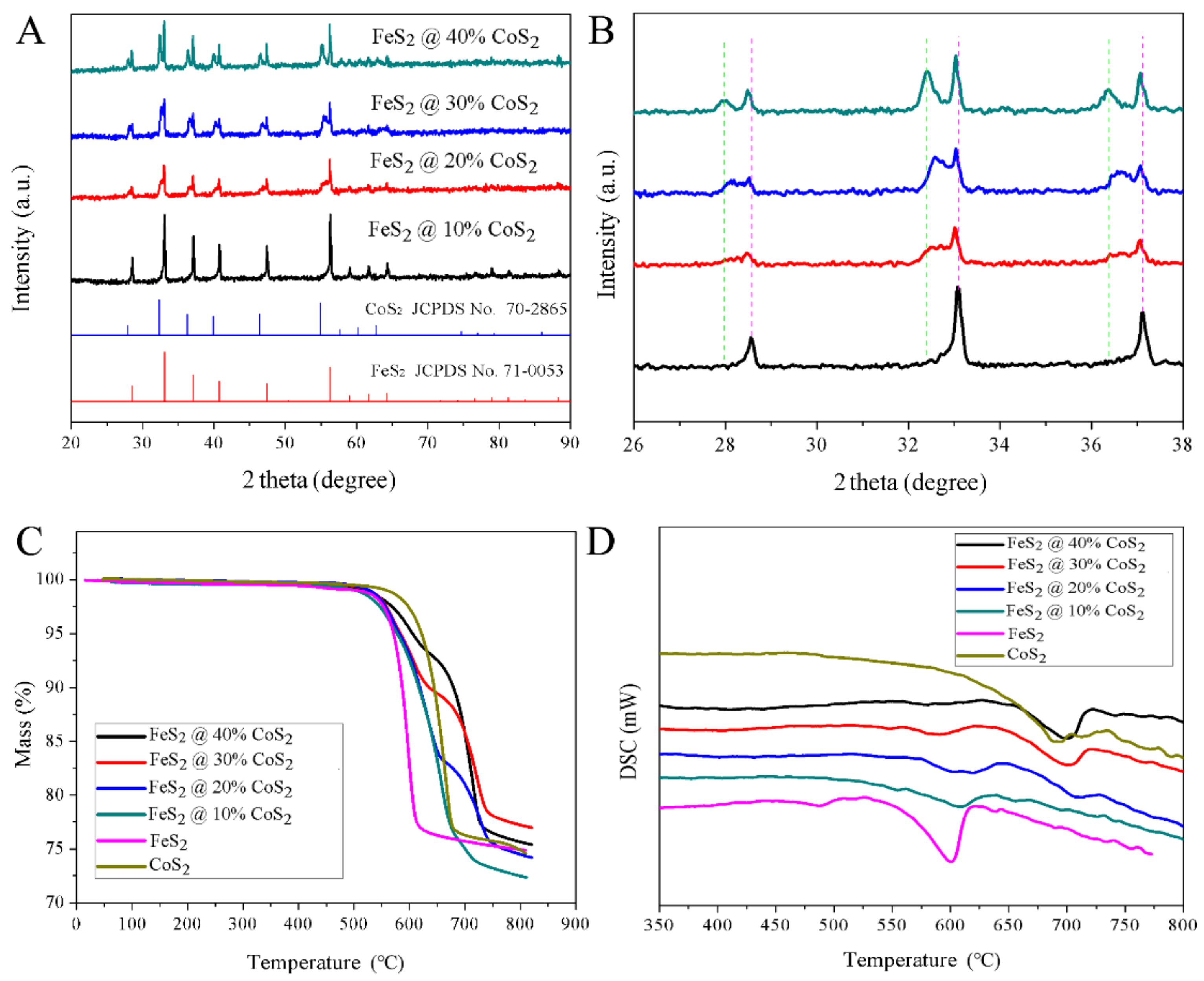
Figure 2 displays the X-ray diffraction (XRD) patterns and thermal properties of prepared FeS
2@CoS
2 with different CoS
2 contents. As can be seen from
Figure 2A, both FeS
2 and CoS
2 belong to pyrite sulfide, and their characteristic diffraction peaks are very similar. Compared with FeS
2, the diffraction peaks of the CoS
2 sample appear at a lower angle. The crystallinity of the synthetic materials is high without other diffraction peaks of sulfide in the XRD patterns, indicating that the pyrite type disulfide pure phase is successfully generated via a high-temperature sulfidation process (
Figure S2). In addition, the diffraction peaks of the FeS
2@CoS
2 composite materials are composed of FeS
2 and CoS
2, indicating that the main phases of the composite cathode are FeS
2 and CoS
2. As shown in the enlarged XRD patterns of FeS
2@CoS
2, the characteristic peaks of FeS
2 shift to a low angle, while the characteristic peaks of CoS
2 shift to a high angle. According to the Bragg equation (2dsin θ =
nλ), if the wavelength of incident light λ is constant, the crystal plane spacing of FeS
2 increases, while that of CoS
2 decreases. The above analysis results demonstrate that the introduction of CoS
2 to FeS
2 is not a simple physical combination, but leads to distortion of the FeS
2 lattice.
As shown in
Figure 2C, the decomposition temperatures of CoS
2 and FeS
2 are 624 and 550 °C, respectively. Moreover, the two single-phase sulfides have only one weight loss step, originating from the sulfur vapor generated by decomposition. The decomposition reaction formula is as follows [
8,
9]:
Two obvious weight loss platforms at 545 °C and 680 °C can be observed in the thermogravimetric curves of the FeS
2@CoS
2 composites. The first platform is close to the decomposition temperature of FeS
2. The secondary decomposition is mainly the decomposition of CoS
2, but is slightly higher than decomposition temperature of CoS
2, which benefits from the structure of the composite material. At about 550 °C, FeS
2 decomposes to produce sulfur vapor, which is prevented by the surface coated CoS
2 and cannot escape. On the thermogravimetric curve, it can be clearly observed that the weight loss rate slows down, and the higher the content of CoS
2 in the composite material, the slower the weight loss. Meanwhile, the sulfur vapor generated by decomposition forms a sulfur vapor concentration enrichment zone in the material, which will inhibit the decomposition of CoS
2 from the perspective of thermodynamics, appropriately increasing the decomposition temperature of CoS
2 to achieve a synergistic effect in the thermal stability of FeS
2 and CoS
2. There are two endothermic peaks in the DSC curves (
Figure 2D) of all FeS
2@CoS
2 samples, corresponding with the thermal decomposition of FeS
2 and CoS
2, respectively, which is consistent with the results of thermogravimetric analysis. With the increasing content of CoS
2 in the sample, the decomposition endothermic peak at 550–650 °C gradually weakens, while the endothermic peak at 650–750 °C becomes stronger. Moreover, no other peaks appear on the differential thermal curve, indicating that the synthesized material is the cobalt iron disulfide phase without another intermediate transition state, which can meet the composition uniformity and stability requirements of a cathode material.
To determine the microstructure of the material, sulfides with different cobalt contents were characterized by scanning electron microscopy (SEM). The FeS
2 core used in the sample synthesis was solid, dense, and smooth, without vertical and horizontal gullies (
Figure 3A,B). As shown in
Figure 3C–J, as the content of CoS
2 continuously increases, the coral dendritic structure surface of the product gradually becomes rough, which is consistent with the results after desulfurization (
Figure S3). Observations at higher magnification revealed that the dendritic structure can mainly be ascribed to the aggregation and growth of small particles. The special morphology is conducive to increasing the contact area with the electrolyte to enhance the high current loading capacity. Moreover, the coral gully-like structure also contributes to improving the adsorption capacity of the electrolyte, preventing the electrolyte from flowing at high temperatures and achieving greater security of the batteries.
Figure 3K shows the morphology schematic of the FeS
2@CoS
2 samples. Since FeS
2 and CoS
2 are both cubic pyrite structures, and CoS
2 grows evenly on the surface of FeS
2, particles with FeS
2 as the core and CoS
2 as the shell are formed. Moreover, according to the mapping result of FeS
2@40%CoS
2 (
Figure S4) and the particle size distribution diagram (
Figure S5), the composition of iron, cobalt, and sulfur is relatively uniform, indicating that CoS
2 and FeS
2 are well-distributed on a large particle scale.
To further confirm the structure and composition of the samples reliably, transmission electron microscopy (TEM) was also applied to characterize the sample FeS
2@40%CoS
2. As illustrated in
Figure 4A, the FeS
2@40%CoS
2 sample contained iron, cobalt, and sulfur, and iron was mainly concentrated in the core, while cobalt was mainly distributed in the edge area. In addition, the 0.27-nm interlayer distance corresponded to the (2 0 0) crystal plane of CoS
2 in the HRTEM of FeS
2@40%CoS
2 (
Figure 4B), indicating that the nanoparticles with a coral dendritic structure are mainly composed of CoS
2 (
Figure S6). Hence, FeS
2@40%CoS
2 can be considered as the structure of FeS
2 as the core and CoS
2 as the shell, which is conductive to enhancing the thermal stability of the material.
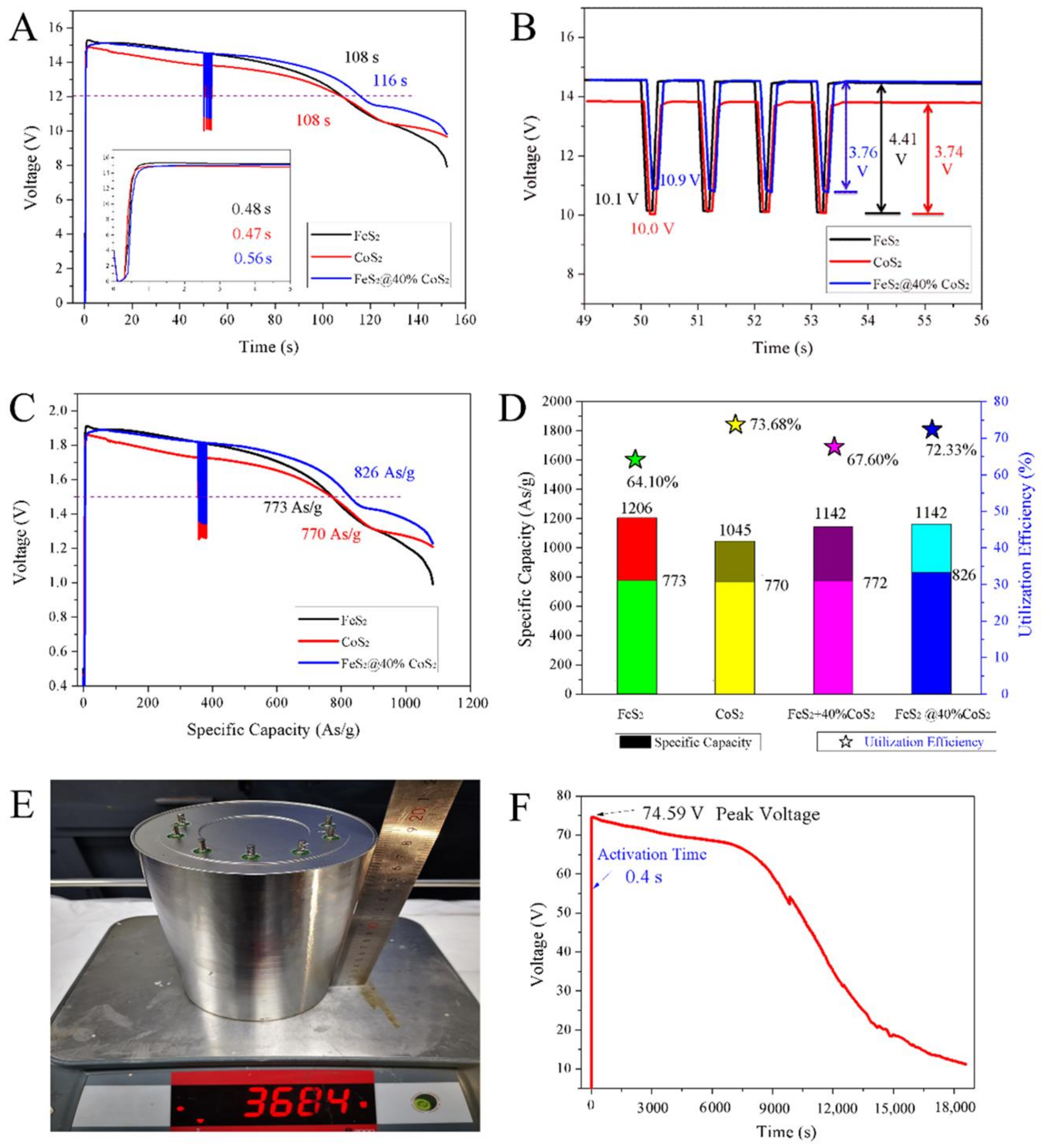
Figure 5 displays the discharge performances of thermal batteries composed of eight single cells with FeS
2, CoS
2, and FeS
2@40%CoS
2 cathodes. The discharge times of batteries with FeS
2, CoS
2, and FeS
2@40%CoS
2 at 1 A/cm
2 were 108 s, 108 s, and 116 s, with the cut-off voltage of 12 V (
Figure 5A). By comparison, FeS
2@40%CoS
2 exhibits the optimal performance, and the working time is increased by 7.4%. According to the enlarged diagram of activation time, the activation times of FeS
2, CoS
2, and FeS
2@40%CoS
2 thermal batteries are 0.48 s, 0.47 s, and 0.56 s respectively, which are far below the application requirements of an activation time of 1.5 s, indicating that the prepared FeS
2@40%CoS
2 material also possesses the semiconductor properties of sulfide. There is no voltage lag in the activation process, and the voltage can be quickly established, which can satisfy the requirements for rapid activation applications of thermal batteries. Due to the difference in the intrinsic conductivity of materials, the activation time of CoS
2 was the smallest, followed by FeS
2. Due to the existence of a two-phase interface and relatively poor crystallinity, FeS
2@40%CoS
2 presents a longer activation time.
As shown in the voltage variation diagram under the super current density of 5 A/cm
2 (
Figure 5B), the voltage drop of CoS
2 thermal batteries is the smallest, at only 3.74 V, but the voltage platform is relatively low, at about 13.8 V. The voltage drops and voltage platform of FeS
2 thermal batteries are about 4.41 V and 14.6 V, respectively. Obviously, FeS
2@40%CoS
2 has both the high voltage platform of FeS
2 and the low voltage drop of CoS
2. The voltages of FeS
2, CoS
2, and FeS
2@40%CoS
2 thermal batteries decreased to 10.1 V, 10 V, and 10.9 V at 5 A/cm
2. As calculated by Ohm’s law, the internal resistance values of the FeS
2, CoS
2, and FeS
2@40%CoS
2 thermal batteries were 67.5 mΩ, 79.6 mΩ, and 67.9 mΩ, respectively, so FeS
2@40%CoS
2 demonstrates the best high current load performance.
Figure 5C shows the relationship between voltage and specific capacity of a single cell. As shown, under the current density of 1 A/cm
2, the peak voltages of FeS
2, CoS
2, and FeS
2@40%CoS
2 single cells were 1.92 V, 1.86 V, and 1.89 V, respectively, wherein the voltage of FeS
2@40%CoS
2 was between FeS
2 and CoS
2. Based on the electrical engineering principle, when FeS
2 and CoS
2 are used as an external power supply at the same time, due to the voltage difference between them, FeS
2 will charge to CoS
2, resulting in the decrease of the potential of FeS
2 and the increase of the potential of CoS
2. The specific capacity values of a single cell with FeS
2, CoS
2, and FeS
2@40%CoS
2 cathodes were 773 As/g, 770 As/g, and 826 As/g, respectively, and the specific capacity of FeS
2@40%CoS
2 was increased by 7.3% with the cut-off voltage of 1.5 V.
Figure 5D describes the specific capacity and utilization efficiency of different sulfide cathodes. The specific capacities of FeS
2 and CoS
2 were 1206 As/g and 1045 As/g. At 1 A/cm
2, the utilization rate of the FeS
2 cathode was 64.10%, while that of the CoS
2 cathode was 73.68%. According to the ratio of FeS
2 and CoS
2 in the composite, the theoretical capacity and utilization rate of 60%FeS
2 + 40%CoS
2 were 1142 As/g and 67.6%. However, the actual output specific capacity and utilization rate of the sample were as high as 826 As/g and 72.33%, revealing that there is an obvious synergistic effect in the FeS
2@40%CoS
2 cathode. The synergistic effect can be explained as follows: First, compared with FeS
2, CoS
2 has higher thermal stability, which weakens the thermal decomposition at high temperatures and improves the effective utilization rate of the cathode material. Second, FeS
2 itself has a high voltage platform and large theoretical capacity, based on an improved utilization rate, delivering a higher capacity. Third, the conductivity of FeS
2@40%CoS
2 is greatly improved compared with that of FeS
2, characterizing a lower internal resistance and stronger power output capacity.
This synthetic method can be extended to a large number of FeS
2@CoS
2 hybrids with over ten grams scale (
Figure S7). Moreover, to explore the safety, large-scale (Φ110 × 180) thermal batteries (
Figure 5E) were assembled made up of 36 single cells with an FeS
2@40%CoS
2 cathode. As depicted in
Figure 5F, the voltage curve was gentle and smooth, without a rapid voltage drop or sharp fluctuation in 18,000 s. The no-load result indicated that there is no short circuit or combustion of the thermal battery, revealing no serious decomposition or heating side reaction of the FeS
2@40%CoS
2 cathode.
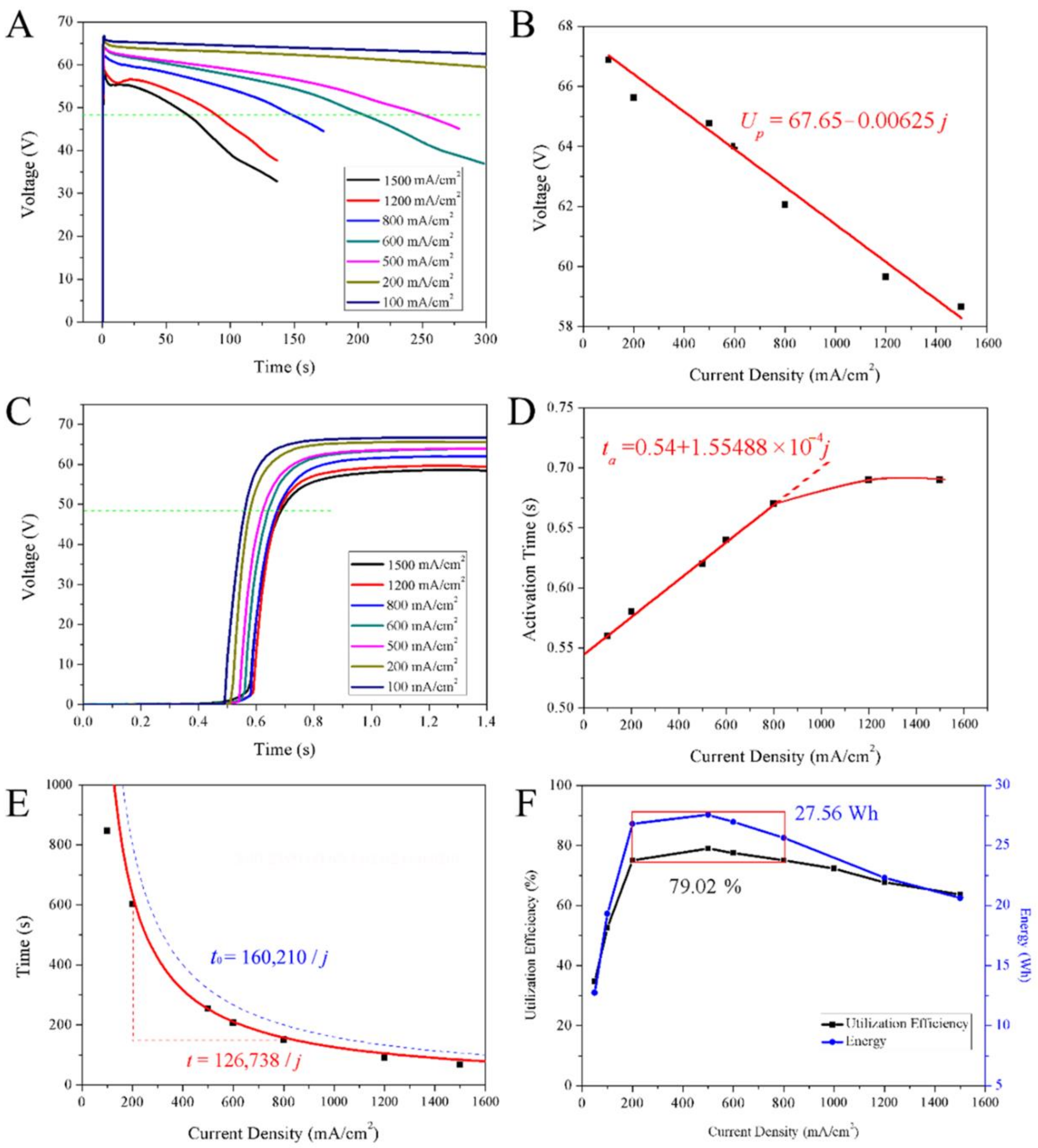
The discharge curves of thermal batteries composed of 33 single cells with FeS
2@40%CoS
2 cathodes are depicted in
Figure 6. At a low current density of 200 mA/cm
2, the discharge voltage was very stable. When the current density was more than 500 mA/cm
2, the voltage decreased gradually with a large slope. When the current density exceeded 1200 mA/cm
2, the voltage may be difficult to load and form a concave peak, as the electrolyte of thermal batteries is a high-temperature molten salt with high conductivity, low internal resistance, and a fast discharge speed. The change of the discharge depth and discharge time will lead to the change of the internal resistance of the batteries. Therefore, in the case of high-speed discharge, the voltage decreases with time in a certain slope.
To prevent a too high peak voltage, the desulfurization process adopted in this study effectively reduced the influence of sulfur impurities. It can be seen from
Figure 6B that the peak voltage decreased linearly with the increase of current density. Based on Ohm’s law
E =
U +
IRi or
U =
E −
IRi, when the battery design parameters remain unchanged, the electromotive force
E and internal resistance
Ri are constant values after activation. The current density
j is positively proportional to the current
I, and the current is in a linear relationship with the open circuit voltage. By fitting, the linear relationship is
U = 67.65 − 0.00625
j. According to the fitting formula, the peak voltage of no-load (
I = 0 A) is 67.65 V, the voltage of LiSi-FeS
2@40%CoS
2 single cell is 2.05 V, and the average internal resistance during activation is about 86 mΩ, suggesting that the internal resistance of the batteries is large at the initial stage of activation.
The activation curves of thermal batteries are smooth ∫ curves (
Figure 6C). This manifestation is mainly related to the melting process of molten salt and the change of conductivity. The electrical conductivity of molten salt has a complex exponential relationship with temperature (
κ =
Ae
(−Eκ/RT)), and the electrical conductivity
κ is related to factor
A and activation energy
Eκ [
24]. At the initial stage of activation, the melting process of molten salt is the main control step, and the open circuit voltage
U of the batteries is proportional to −
j e
(Eκ/RT). Therefore, the electrolyte is in a solid state with a voltage of 0 V in activation. When the temperature rises to near the melting point, the molten salt temperature remains stable for a short time due to the phase transformation (
Figure S8) [
24], and the battery conductivity builds a stable voltage with an exponential relationship. After the phase transformation, the temperature of the molten salt will rise rapidly, and the conductivity will change in an exponential relationship of temperature strengthening, which is manifested as rapidly increasing open circuit voltage. The heating material inside the battery continues to heat the system, so that the temperature of the battery gradually rises and tends to be stabilized, and the open-circuit voltage slowly transitions in an exponential relationship until it becomes stationary. Therefore, the activation process of the battery shows a four-stage variation rule. In the process of establishing voltage in the phase transformation stage of molten salt [
25], the current density has the greatest influence on the activation time (
Figure 6C).
As seen in
Figure 6D, the activation time of the batteries has a linear relationship with the current density in the early stage, and gradually tends towards constant in the later stage. The linear relationship can be fitted as
ta = 0.54 + 1.55488 × 10
−4j, and the activation time
ta of the batteries is 0.54 s without load (
j = 0 mA/cm
2). According to
U∝−
j e
(Eκ/RT), under the premise of a loading large current, e
(Eκ/RT) is a constant value at the same time, and the open circuit voltage is linear with the current density
j. As the current density
j increases, the open circuit voltage is negatively correlated, so the time for the voltage to reach the active voltage is delayed. When the time is long enough, the molten salt completes the phase transformation and starts to heat up rapidly. Even if the current density increases, the activation time will not be affected, and the activation gradually tends towards becoming stable.
Figure 6E shows the influence of current density on working time. The current density is inversely proportional to the working time of the batteries, with the cut-off voltage of 48 V. After data fitting, the relationship between the two can be expressed as
t = 126,738/
j. Calculated with the theoretical specific capacity of FeS
2@40%CoS
2 at 1141.6 As/g, the relationship between current density and working time is
t = 160,210/
j (blue dotted line). After analysis, within the current density range of 200–800 mA/cm
2, the working time is consistent with the red fitting line, and the current density is too high or too low, which deviates from the fitting line.
As shown in
Figure 6F, the utilization rate and output energy of FeS
2@40%CoS
2 increased sharply first and then decreased slowly with increasing current density. In the red box of
Figure 6F, when the current density is in the range of 200–800 mA/cm
2, the maximum output capacity of FeS
2@40%CoS
2 is up to 902 As/g, with a utilization rate of 79.02%, and the maximum energy output is up to 27.56 Wh at 500 mA/cm
2. When the current density is less than 200 mA/cm
2, the electrode material utilization rate decreases sharply, which can be attributed to the long working time. As molten salt batteries, thermal batteries mainly rely on heat to ensure the electrolyte is in the appropriate working temperature zone. Too long a time will lead to heat loss and internal resistance increase, such that some of the FeS
2@40%CoS
2 cannot participate in the electrochemical reaction, resulting in capacity loss. When the current density is larger than 800 mA/cm
2, the polarization resistance increases with the discharge depth, and the FeS
2@40%CoS
2 cannot support the high current load, resulting in a reduced capacity output and utilization rate. Hence, 200–800 mA/cm
2 is the ideal reference current density for thermal battery design, with the highest utilization rate of materials and maximum output energy.


 ,
, 


