Article

Water Management for μDMFC with Foamed Stainless Steel Cathode Current Collector

1
Faculty of Information Engineering and Automation, Kunming University of Science and Technology, Kunming 650500, China
2
Yunnan Key Laboratory of Green Energy, Electric Power Measurement Digitalization, Control and Protection, Kunming 650000, China
*
Author to whom correspondence should be addressed.
Nanomaterials 2022, 12(6), 948; https://doi.org/10.3390/nano12060948
Submission received: 12 February 2022 / Revised: 8 March 2022 / Accepted: 8 March 2022 / Published: 14 March 2022
(This article belongs to the Topic Electromaterials for Environment & Energy)

Abstract

:
For micro direct methanol fuel cell (μDMFC), water flooding on the cathode seriously affects the performance stability. Additionally, the effect of material and wettability of the cathode current collector (CCC) on the drainage capacity is studied to improve the μDMFC’s performance. To this end, a CCC with foamed stainless steel was prepared to assemble the μDMFC due to its absorbency. Further, based on analyzing the gas–liquid two-phase flow characteristics of the μDMFC cathode, it was found that the gradient wettability CCC could accelerate the discharge of cathode water. Hence, the foam stainless steel CCC was partially immersed in a KOH solution to complete the gradient corrosion using its capillary force. Then, four different types of gradient wettability CCC were prepared by controlling the time of chemical corrosion. Finally, the performance of the μDMFC with different gradient wettability CCC was tested at room temperature using electrochemical impedance spectroscopy (EIS) and discharge voltage. The experimental results show that the gradient wettability CCC can improve the performance of the μDMFC by slowing down the rate of cathode flooding. The optimum corrosion time is 5 min at a concentration of 1 mol/L. Under these conditions, the CCC has the best gradient wettability, and the μDMFC has the lowest total impedance. The discharge voltage of the μDMFC with corroded CCC is increased by 33.33% compared to the uncorroded CCC μDMFC. The gradient wettability CCC designed in this study is economical, convenient, and practical for water management of the μDMFC.

1. Introduction

With the rapid development of industry, the rate of consumption of fossil fuels has been dramatic. The micro direct methanol fuel cell (μDMFC), which relies on an internal redox reaction to generate electricity, provides a green route for environmental and energy concerns [1,2,3]. To effectively improve the performance of the μDMFC, in-depth research into cathode flooding should be implemented because excess water can severely block the gas channels and prevent O2 from reaching the reaction sites uniformly [4,5,6,7]. Therefore, water management of the μDMFC is still a key technology [8,9,10,11].
To analyze the emergence of water flooding and the hazards it brings, scholars have developed different physical models for the gas–liquid two-phase flow in the cathode of fuel cells [12,13,14,15,16]. In 2020, Mehnatkesh et al. [17] used a deep neural network model to measure water coverage in fuel cells. The distribution of water in the flow field and the identification of areas of water accumulation in the gas channels were analyzed. In 2021, Rubio et al. [18] proposed a fuzzy model to determine the extent of fuel cells flooding or dehydration in real time. Salaberri et al. [19] used a pore grid model to analyze the relative effect of local water blockage on the gas diffusion layer and convection. Building the physical model of the gas–liquid two-phase flow in the fuel cell cathode is an important research direction [20,21]. However, experimental investigations are an essential part of scientific research, and other scholars have directly observed the water flooding phenomenon at the fuel cell cathode through experiments [22,23,24]. In 2020, Rahimi et al. [25] designed a transparent fuel cell stack and studied the effect of water flow state on voltage and pressure by visualization. In 2021, Chasen et al. [26] combined X-ray imaging and EIS to measure the water in the fuel cell flow field, which showed that the water content of the parallel flow field was much higher than that of the serpentine flow field. Based on theory and experimental investigations, scholars have designed different structures in the membrane electrode and cathode flow fields of fuel cells to mitigate water flooding [27,28]. In 2018, Fly et al. [29] analyzed the fluid distribution in the flow field of the metal foam fuel cell. The experimental results showed that the velocity of water covering the flow field was enhanced by 61% using the foam flow field. In 2019, Yuan et al. [30] used carbon aerogel to construct a water management layer in the membrane electrode of the fuel cell, and they found that the layer enhanced water recovery. In 2020, Karthikkyan et al. [31] placed porous inserts in the flow field to alleviate cathode flooding and showed that the insertion methods and insert specifications had significant effects on the performance of the fuel cell. Sun et al. [32] used foam metal instead of conventional current collectors and found that modifying the foam metal current collector with wettability could improve the performance of the fuel cell. Overall, the application of treated porous metals to μDMFC can effectively mitigate cathode flooding.
In this study, the cathode current collector (CCC) was prepared using foamed stainless steel, and the gas–liquid two-phase flow characteristics of the μDMFC cathode were analyzed. Then, the foam stainless steel CCC was partially immersed in a KOH solution to complete the gradient corrosion using its capillary force. The gradient wettability CCC can create a gradient force to accelerate the drainage in the cathode of the μDMFC. Compared to modified membrane electrode structures and flow field structures, the method of gradient wettability modification has the advantage of being economical, simple, and efficient. Those CCCs were classified according to the corrosion time: uncorroded CCC (N-CCC), 1 min corroded CCC (1-CCC), 5 min corroded CCC (5-CCC), and 9 min corroded CCC (9-CCC). Finally, the μDMFC with different gradient wettability CCC were tested at room temperature using EIS and discharge voltage.

2. Methods and Experiments

2.1. Gas–Liquid Two-Phase Flow in the Cathode of μDMFC

The μDMFC’s structure is shown in Figure 1. The fabrication of the various parts of the μDMFC is the same as in the previous study [33]. The material of the CCC is foam stainless steel, and the flow field is of hole type, as shown in Figure 2. Then, the gas–liquid two-phase flow characteristics in the cathode of the μDMFC are analyzed to find a method that can enhance the performance.
The flow state of the liquid within the CCC is related to the permeability. According to Darcy’s law:
Δ P l p = μ l m ˙ Δ L ρ l K π r e f f 2
where Δ P l p is the pressure drop of the fluid, m ˙ is the flowing mass, Δ L is the distance, ρ l is density, μ l is kinetic viscosity, r e f f is the effective radius of the wick, and K is the permeability of the CCC. The capillary pressure of the CCC is calculated as follows:
Δ P c p = 2 σ cos θ r e f f
where Δ P c p is the capillary pressure provided by the CCC, σ is the surface tension of the H2O, and θ is the contact angle. When the pressure drop of the liquid flow is equal to the capillary pressure, the maximum flow rate of water in the CCC is calculated as follows:
m ˙ l , m a x = 2 ρ l K π r e f f σ cos θ μ l Δ L
where m ˙ l , m a x is the maximum flow rate of water in the CCC. It can be seen from Equation (3) that reducing the contact angle can increase the flow rate of water and thus the timely discharge of water that accumulates in the flow field.
Air flows mainly in a hole-type flow field, the flow state of which can be represented by the Hagen–Poiseuille equation:
Δ P a p = 32 μ a u ¯ a Δ L D 2
where Δ P a p is the pressure drop of the air, μ a is the viscosity of the air, u ¯ a is the average flow rate of the air, and D is the effective diameter of the hole-type flow field. Further, the oxygen flow rate is calculated as follows:
m ˙ o = Δ P a p ρ a π D 4 128 μ a Δ L × w t %
where m ˙ o is the flow rate of oxygen in the flow field, ρ a is the density of air, and w t % is the mass fraction of oxygen. As can be seen from Equation (5), the flow rate of oxygen is proportional to the fourth power of the effective diameter of the flow field. If the CCC is not drained in time, the hole-type flow field will be blocked by excess water, resulting in the oxygen not reaching the cathode catalytic layer smoothly.
Overall, making a wettability modification to the foam stainless steel CCC can slow down cathode flooding and thus improve the performance of the μDMFC.

2.2. Gradient Wettability Modification for the CCC

For the gradient wettability modification of the CCC:
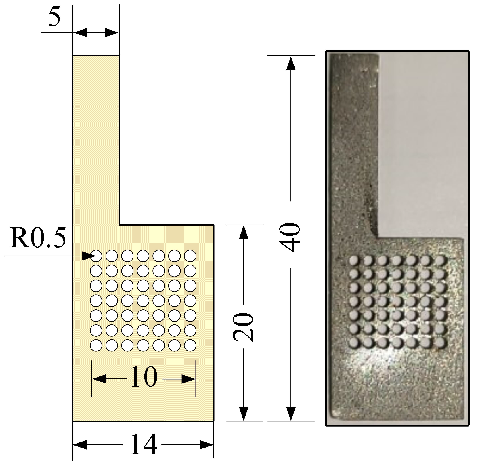
  • Using a laser cutting platform (Type 6060L-1000W), the CCC with the foamed stainless steel was machined, and then the surfaces of these CCC were polished smooth;
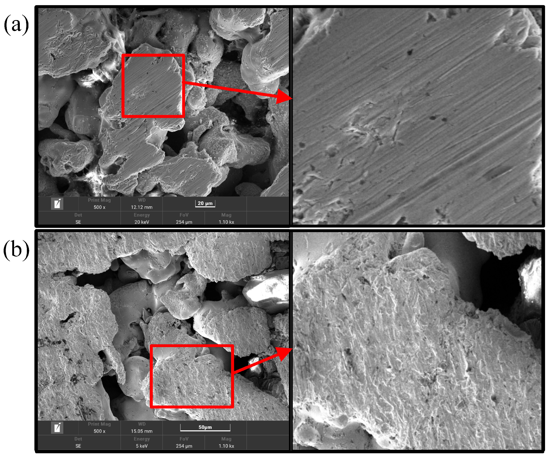
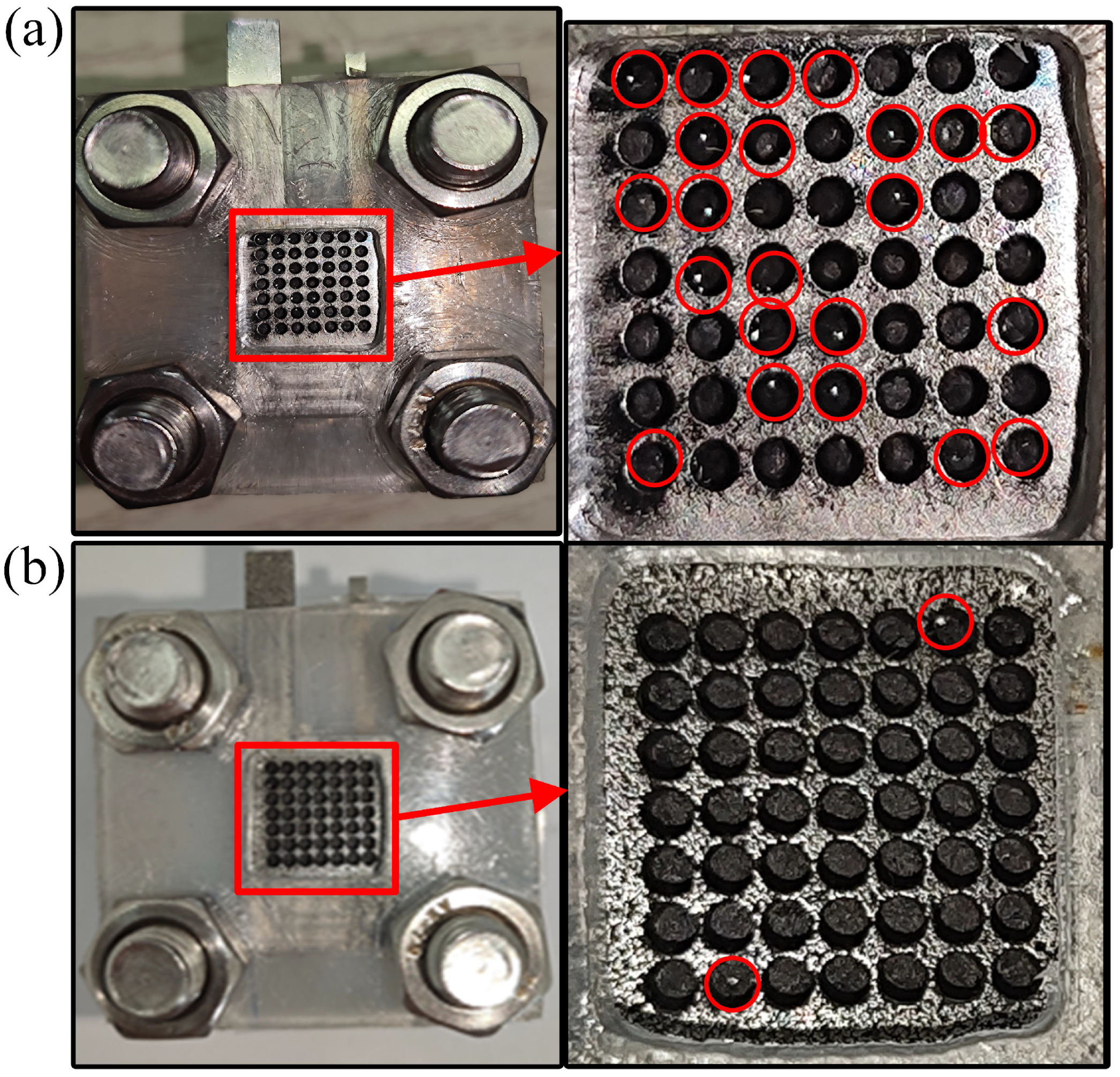
  • The CCC was cleaned with methanol, ethanol, and deionized water in turn, and then the dried CCC was immersed in the KOH solution of 1 mol/L to corrode. As shown in Figure 3a, the CCC was placed vertically with the bottom immersed to a depth of 2 mm;
  • Finally, the treated CCC was rinsed in deionized water and dried in a drying oven.
During the treatment, the bottom of the CCC was immersed in the KOH solution, and then the solution climbed upwards under the capillary force. However, due to gravitational and viscous forces, the greater the height of the CCC, the smaller the mass of the climbed solution, resulting in a weaker corrosion strength. For ease of analysis, the CCC after modification was divided equally into three regions, α , β , and γ , as shown in Figure 3b.
The surface morphology of the CCC was analyzed. The selected equipment was TESCAN MIRA4, and an Oxford energy spectrometer was chosen. The scanning electron microscope (SEM) image shows that the surface of the CCC before the wettability modification has only a few tiny scratches, while the surface of the CCC after the wettability modification has a layer of a nanostructure, as shown in Figure 4. This layer of nanostructure corroded by the KOH solution shows a uniform character and increases the surface roughness of the CCC. Compared to the prolonged hydroxide molten salt corrosion [34] and the electrochemical corrosion of the salt solution [35], the surface morphology of the CCC after the wettability modification is not substantially damaged. Therefore, the method does not significantly destroy the CCC’s mechanical strength and electrical conductivity.
According to the Wenzel model:
c o s θ w = R A F c o s θ
where θ w is the Wenzel contact angle and R A F is the roughness of the wetted area. It can be seen that the nanostructure of the CCC surface can increase the surface roughness and reduce the contact angle.
The wettability modification can increase the capillary force and provide an additional capillary gradient force for the foamed stainless steel CCC. This increases the drainage capacity of the foam stainless steel CCC so that the μDMFC does not flood under high-intensity operating conditions.

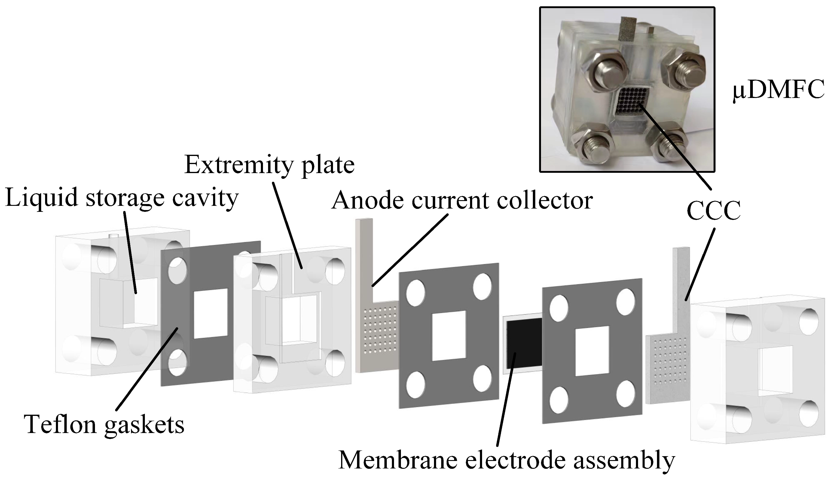
2.3. Test System for μDMFC

The test system consists of a DC electronic load, an electrochemical workstation, and a thermostat, as shown in Figure 5. This test system can perform EIS, discharge, and polarisation curve tests for the μDMFC with different gradient wettability CCC. Before testing, the μDMFC was activated to bring the μDMFC into operation state [31,32]. Afterwards, the μDMFC was placed in a 25 °C thermostat and connected to the DC electronic load and the electrochemical workstation.

3. Results and Discussion

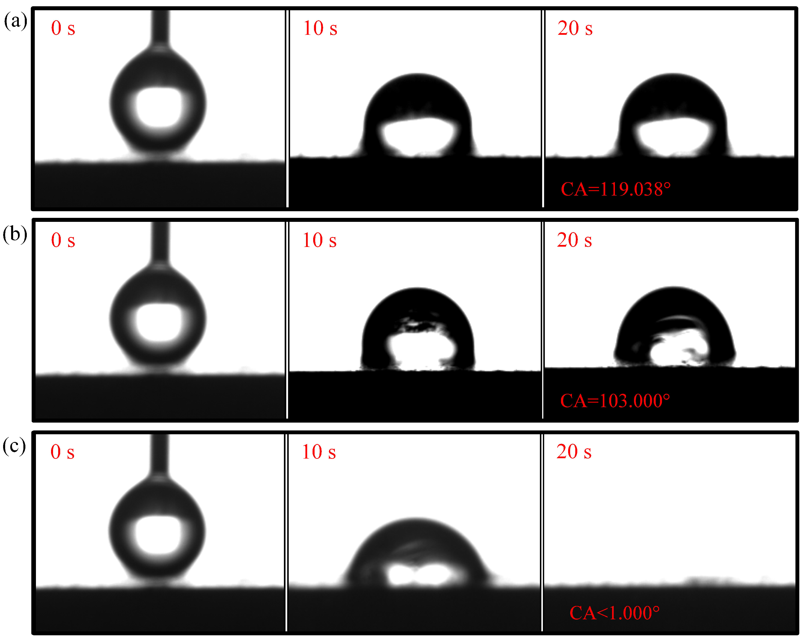
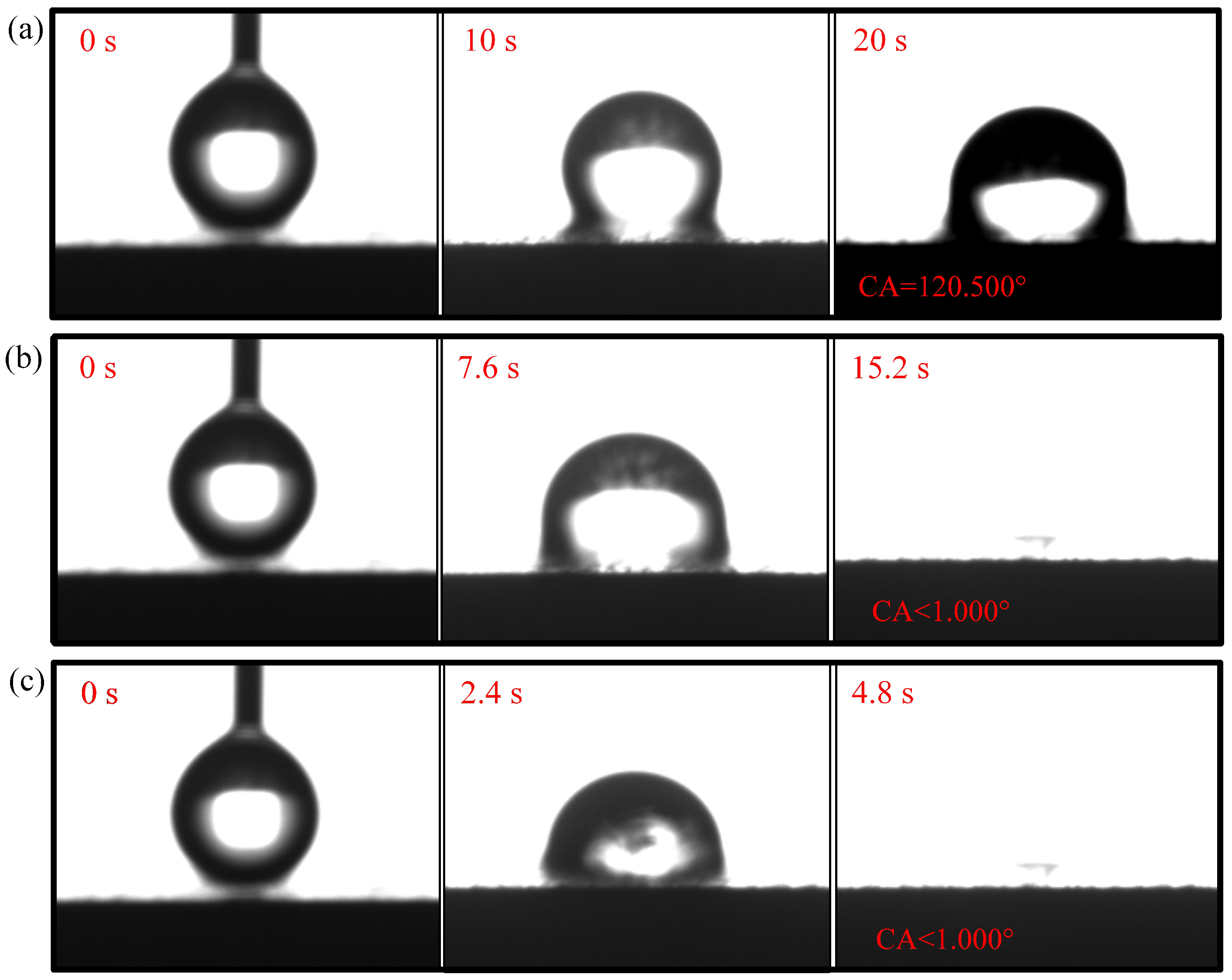
3.1. Wettability Test

The contact angle for N-CCC is 120.905 , as shown in Figure 6. This is mainly caused by the air inside the foamed stainless steel reducing the surface energy, which results in a hydrophobic appearance, i.e., a contact angle greater than 90 . After the different wettability modifications, the α , β , and γ regions of the CCC all have a hydrophilic tendency, as shown in Figure 7, Figure 8 and Figure 9.
The droplet in the α region of the 1-CCC appears in suspension, and its contact angle is always 119.038 . The droplet in the β region of the 1-CCC appears to complete a slow penetration, and the contact angle drops to 103.00 at 20 s. In contrast, the droplet in the γ region took 20 s to penetrate completely. In the hydrophilic case, once the droplet comes into contact with the surface, it is drawn into the capillary pores by the driving force generated by the capillary effect [30,36]. From this, it is clear that the γ region of the 1-CCC is more hydrophilic than the β and α regions. Furthermore, it can be seen that the KOH solution can climb upwards along with the foamed stainless steel CCC by capillary forces to gradient-corrode the CCC. Additionally, the short immersion time results in a small mass of climbing KOH solution, and thus the β and α regions show hydrophobicity. For the 5-CCC, the droplet in the α region appears suspended, while the droplets in the β and γ regions appear to conduct a complete penetration. The penetration time of the droplets in the β and γ regions are 15.2 s and 4.8 s, respectively. This result implies that with increasing immersion time of the CCC, the mass of the climbing KOH solution increases, and thus complete permeation occurs in the β region. For 9-CCC, the α , β , and γ regions all feature complete permeation. Their permeation times are 3.9 s, 2.3 s, and 1.7 s, respectively. This implies that the longer immersion time makes the KOH solution climb upwards in large quantities, which results in severe corrosion of the entire foamed stainless steel CCC. Therefore, the overall 9-CCC displays a hydrophilic state.
The gradient behavior of the CCC after the wettability modification is shown in Table 1. According to the listed results, 119.038 –<1 for 1-CCC, 120.500 –<1 for 5-CCC, and < 1 –<1 for 9-CCC. Furthermore, it can be seen that the hydrophilicity of the γ region of 5-CCC is superior to that of the γ region of 1-CCC because the droplet in the γ region of 5-CCC can penetrate more rapidly. Thus, the 9-CCC is almost without gradient wettability, and the 5-CCC has an optimal gradient wettability. Further, gradient wettability can generate gradient force to pull the liquid water to move directionally. The reason is that the more hydrophilic the wall, the stronger the adhesion between the droplet and the wall [3,37]. As the adhesion force increases, the contact area between the droplet and the wall increases, which causes the droplet to move towards higher hydrophilicity [38].

3.2. Cathode Flooding
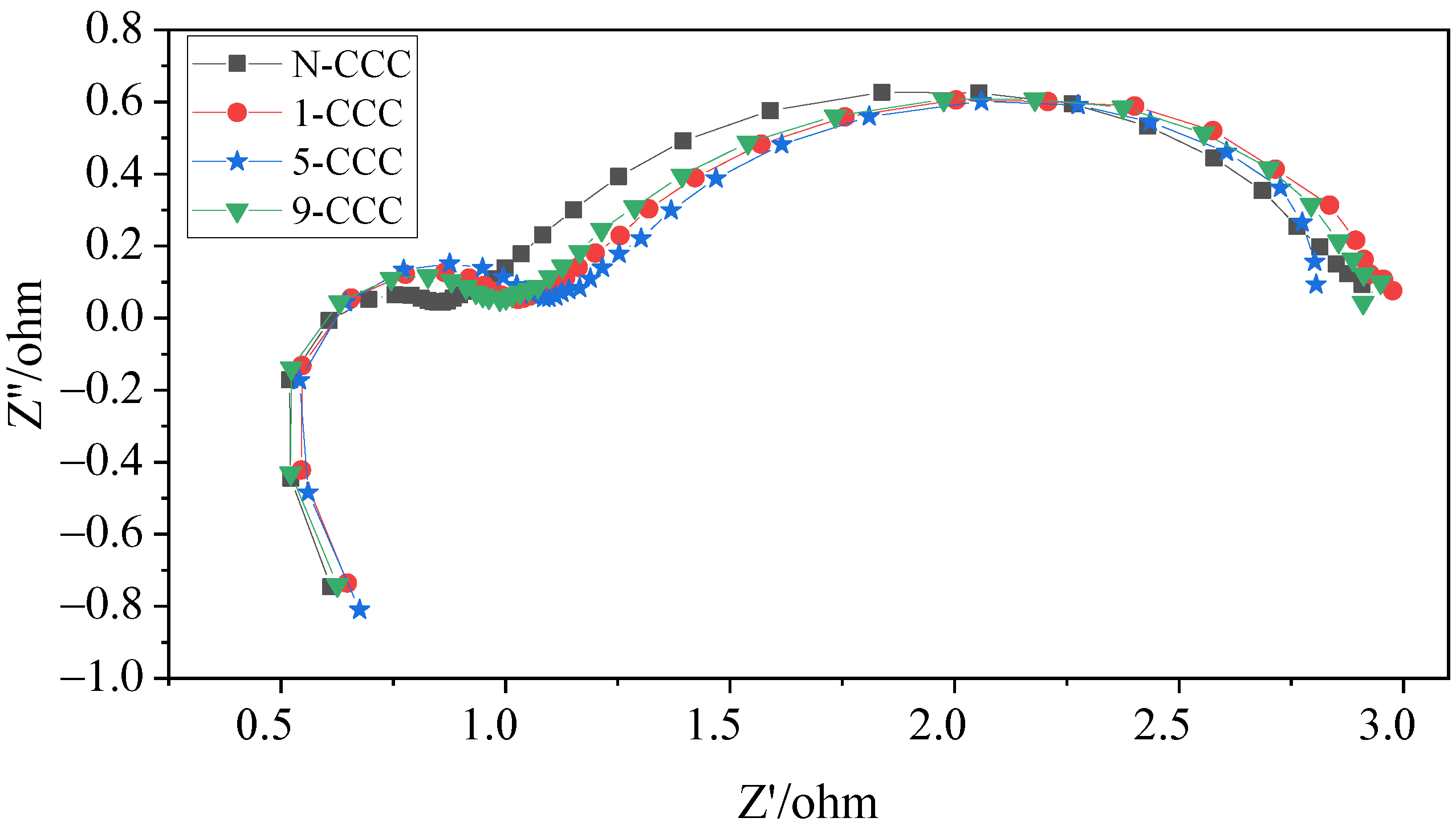
During the discharge process, water molecules are generated in the cathode of the μDMFC. The accumulation of these water molecules for a long time will form liquid water and affect the performance of the μDMFC. As shown in Figure 10, the μDMFC are discharged at 50 mA/cm2 current to observe flooding of the hole-type flow field. It can be seen that most of the liquid water was in the cathode of the stainless steel μDMFC, while little of the liquid water was in the cathode of the foamed stainless steel μDMFC. This is because the liquid water of the foamed stainless steel μDMFC is absorbed into the micropores by the capillary force. Moreover, this absorbing process does not change the water content inside the cathodic catalytic layer and does not affect the hydraulic pressure inside the membrane electrode assembly [30]. Therefore, the foamed stainless steel is suitable for water management studies with μDMFC.
The polarization curves of the foamed stainless steel μDMFC were tested to find the optimum methanol solution concentration required for the discharge. As shown in Figure 11, the maximum power of the foam stainless steel μDMFC can reach 15.5 mW at a methanol solution concentration of 4 mol/L. Therefore, the methanol solution selection is 4 mol/L. Additionally, to perform a long and stable discharge of the μDMFC with different gradient wettability CCC, the current density selection is 80 mA/cm2, and the discharge time selection is 150 min [32].

3.3. EIS

In this work, to investigate in depth the effect of the CCC with different gradient wettability on the performance of the μDMFC, AC impedance tests before and after discharge were carried out, as shown in Figure 12 and Figure 13. Their contact impedance and total impedance are shown in Table 2. It can be seen that, before discharge, the contact impedance of the μDMFC with different gradient wettability CCC is 0.61 Ω [39]. However, the charge transfer impedance of N-CCC μDMFC is the smallest. This is because the surface of the gradient wettability CCC is corroded, which reduces its conductivity and leads to an increase in charge transfer impedance. After discharge, the EIS of the μDMFC with different gradient wettability CCC changed significantly. Their total and mass transfer impedance increased significantly, but the contact impedance decreased to 0.50 Ω [31,40]. This is because the water emerging in the cathode floods the catalytic layer, which increases the concentration loss and oxygen transfer resistance [1,26]. However, the water accumulated by prolonged discharge can raise the relative humidity of the reactant gas and further increase the water content in the membrane [7]. Increasing the level of membrane hydration can enhance the proton mobility and thus the electrical conductivity of the membrane [26,32].
In the low-frequency range, the μDMFC of 5-CCC has the smallest curve radius, while the μDMFC of N-CCC has the largest curve radius. Furthermore, the μDMFC of 1-CCC and 9-CCC have essentially the same curve radius, as shown in Figure 13. Thus, the total impedance of the μDMFC of 1-CCC and the μDMFC of 9-CCC are essentially the same. The μDMFC of 5-CCC has the lowest total impedance, while the μDMFC of N-CCC has the highest total impedance. This result implies that the cathode flooding of the μDMFC differs for the different gradient wettability CCC. The 5-CCC has the most suitable gradient wettability and can effectively direct water towards the end of the CCC. Hence, it can release the flow field channels and microporous channels of the CCC to provide more oxygen in the cathode of the μDMFC. The 1-CCC and the 9-CCC have relatively poor capillary gradient force and cannot effectively direct water towards the end of the CCC. Thus, it cannot effectively enhance the oxygen transfer rate on the cathode side. The N-CCC does not have capillary gradient force and cannot tract water from the CCC towards the end. Thus, it has a high resistance to oxygen transfer, which leads to increased cathodic polarization.
In general, after prolonged discharge, the total impedance of the μDMFC increases significantly, and the mass transfer impedance increases more than the charge transfer impedance. This implies that the effect of the mass transfer impedance on μDMFC performance is much greater than that of the charge transfer impedance under prolonged discharge. The use of wettability gradient force can increase oxygen transfer channels and improve mass transfer rate. Thus, it can effectively enhance the μDMFC’s performance.

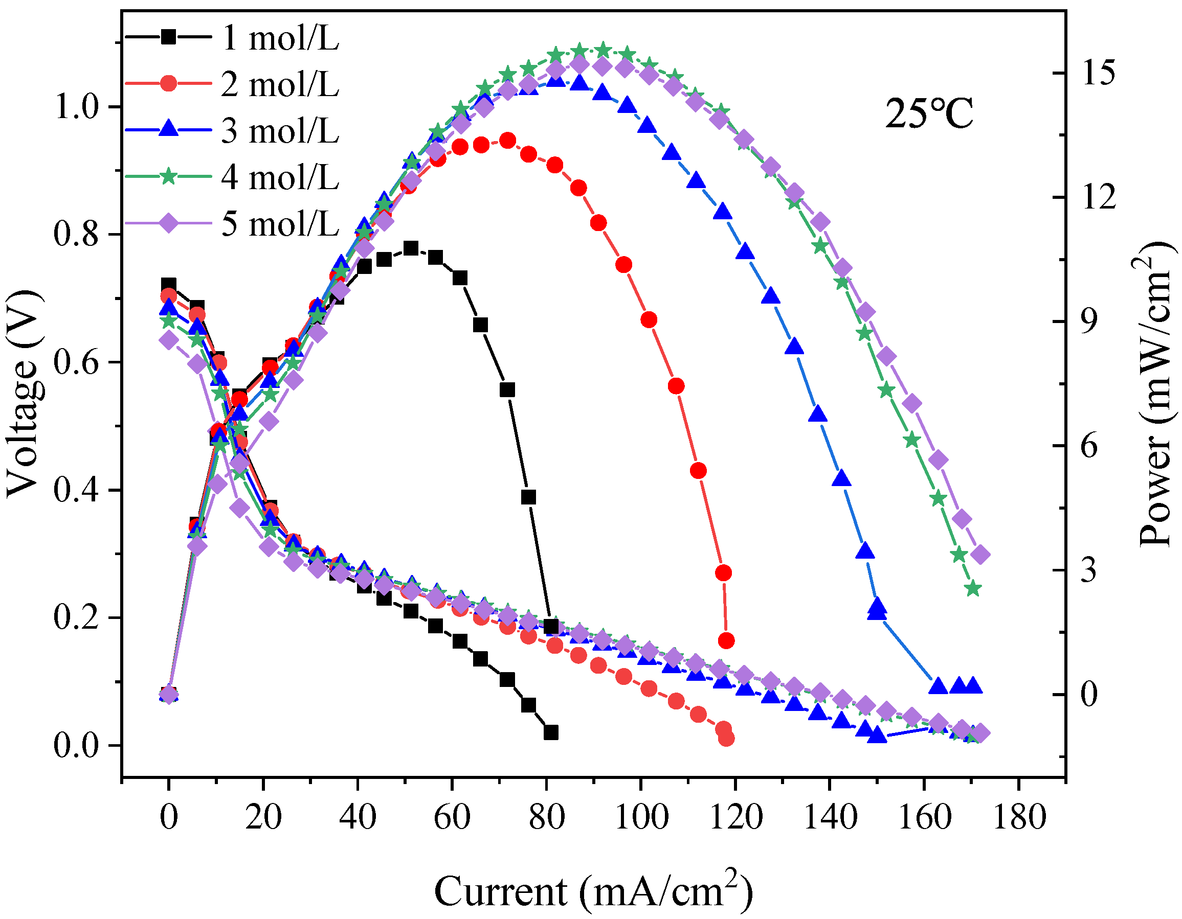
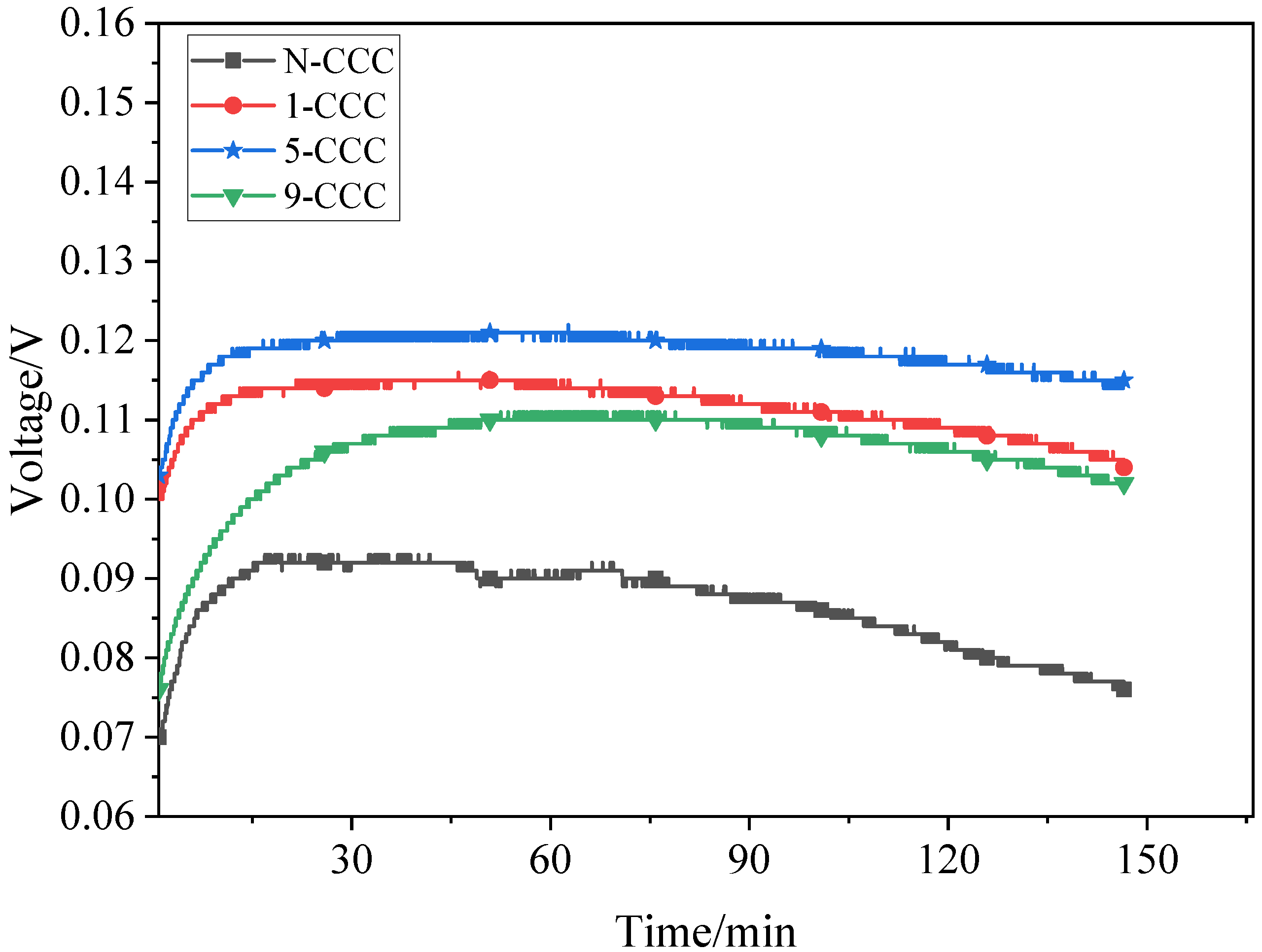
3.4. Discharge Voltage

Discharge voltage tests are carried out for different types of μDMFC with a methanol solution of 2 mL, as shown in Figure 14. At 1 h, the discharge voltage of the N-CCC μDMFC is 0.09 V. Compared to it, the discharge voltage of the 5-CCC μDMFC, 1-CCC μDMFC, and 9-CCC μDMFC increased by 33.33%, 27.28%, and 23.33%, respectively. This is because the large amount of liquid water produced by the cathode during the prolonged discharge blocks the microporous channels of the CCC, making the oxygen transport path less accessible. However, the gradient wettability CCC can effectively pull the water generated in the cathode towards the end of the CCC, and the particulate water in microporous channels evaporates more quickly, which can make the microporous channels of the CCC unobstructed and increase the drainage rate and oxygen transfer rate [41,42].
During the discharge process, the performance of the N-CCC μDMFC decreases the fastest while the performance of the 5-CCC μDMFC decreases the slowest. Additionally, the performance of the 1-CCC and 9-CCC μDMFC decreases at approximately the same rate. This implies that as the redox reaction progresses, more and more liquid water accumulates in the cathode of the μDMFC. The accumulation of liquid water reduces the transfer of oxygen to the membrane electrode assembly, which increases the polarization losses and makes the local current density distribution in the μDMFC very non-uniform. The μDMFC with suitable gradient wettability shows better performance stability.
The performance of the μDMFC is affected by the accumulation and distribution of liquid water [24]. If liquid water is not discharged from the cathode side in time, the diffusion efficiency of the gas is significantly reduced. Further, this can cause a rapid and unstable degradation in the performance of the μDMFC and affect the lifetime of the μDMFC [15].

4. Conclusions

In this study, for the foamed stainless steel μDMFC, a gradient wettability CCC was prepared to avoid cathode flooding by analyzing the gas–liquid two-phase flow characteristics. Then, to find the suitable corrosion time, the wettability of four different types of CCC was tested. At room temperature, the μDMFC with different gradient wettability CCC were tested using EIS and discharge voltage. The main conclusions are as follows:
  • The foamed stainless steel is more suitable to prepare the gradient wettability CCC for water management of μDMFC cathode. The gradient of wettability of the 5-CCC is 120.500 –< 1 . It is significantly better than the 1-CCC and 9-CCC. At 5 min treatment time conditions, the KOH solution of 1 mol/L can provide optimal gradient corrosion for the CCC;
  • After discharge of 150 min, the 5-CCC μDMFC has the lowest total impedance, whereas the N-CCC μDMFC has the highest total impedance. The 5-CCC has the most suitable gradient wettability and can effectively direct water towards the end of the CCC. Thus, it has more flow field channels and microporous channels and can provide more oxygen to the cathode of the μDMFC;
  • At 1 h, compared to the N-CCC μDMFC, the discharge voltage of the 1-CCC μDMFC, 5-CCC μDMFC, and 9-CCC μDMFC increased by 27.28%, 33.33%, and 23.33%, respectively. The μDMFC with gradient wettability CCC shows better stability and higher discharge voltage.

Author Contributions

Conceptualization, F.Z. and Z.Z.; methodology, F.Z. and Y.Z.; software, Y.Z. and F.Z.; validation, Z.Z., F.Z. and Y.Z.; formal analysis, F.Z.; investigation, F.Z.; resources, Z.Z.; data curation, F.Z.; writing—original draft preparation, F.Z. and Y.Z.; writing—review and editing, F.Z. and Z.Z.; visualization, Y.Z.; supervision, Z.Z.; project administration, Z.Z.; funding acquisition, Z.Z. All authors have read and agreed to the published version of the manuscript.

Funding

This work is partly supported by the National Natural Science Foundation of China (Grant No. 62162035) and the Applied Basic Foundation of Yunnan Province (Grant No. 202101AT070131, 202101AT070309).

Institutional Review Board Statement

Not applicable.

Informed Consent Statement

Not applicable.

Data Availability Statement

Not applicable.

Acknowledgments

The contributions of all my coauthors are gratefully acknowledged. Thanks are extended to the National Natural Science Foundation of China and the Applied Basic Foundation of Yunnan Province.

Conflicts of Interest

The authors declare no conflict of interest.

Abbreviations

The following abbreviations are used in this manuscript:
μDMFCMicro direct methanol fuel cell
CCCCathode current collector
EISElectrochemical impedance spectroscopy
SEMScanning electron microscope
N-CCCUncorroded CCC
1-CCC1 min corroded CCC
5-CCC5 min corroded CCC
9-CCC9 min corroded CCC
Δ P Pressure drop, capillary pressure
m ˙ Flowing mass
Δ L Distance
ρDensity
μKinetic viscosity
r e f f Effective radius
KPermeability
σ Surface tension
θ Contact angle
u ¯ Average flow rate
DEffective diameter
w t % Mass fraction
Subscript lLiquid
Subscript aAir
Subscript oOxygen

References

  1. Shanmugasundaram, S.; Rajaram, G.; Karthikeyan, P.; Vasanth, R.J. Comparison of perforated and serpentine flow fields on the performance of proton exchange membrane fuel cell. J. Energy Inst. 2017, 90, 363–371. [Google Scholar]
  2. Liu, C.; Hu, S.; Yin, L.; Yang, W.; Yu, J.; Xu, Y.; Li, L.; Wang, G.; Wang, L. Micro Direct Methanol Fuel Cell Based on Reduced Graphene Oxide Composite Electrode. Micromachines 2021, 12, 72. [Google Scholar] [CrossRef]
  3. Vijayakrishnan, M.K.; Palaniswamy, K.; Ramasamy, J.; Kumaresan, T.; Manoharan, K.; Rajagopal, T.K.R.; Maiyalagan, T.; Jothi, V.R.; Yi, S.-C. Numerical and experimental investigation on 25 cm2 and 100 cm2 PEMFC with novel sinuous flow field for effective water removal and enhanced performance. Int. J. Hydrogen Energy 2020, 45, 7848–7862. [Google Scholar] [CrossRef]
  4. Hasheminasab, M.; Kermani, M.J.; Nourazar, S.S.; Khodsiani, M.H. A novel experimental based statistical study for water management in proton exchange membrane fuel cells. Appl. Energy 2020, 264, 114713. [Google Scholar] [CrossRef]
  5. Yang, Z.; Du, Q.; Jia, Z.; Yang, C.; Jiao, K. Effects of operating conditions on water and heat management by a transient multi-dimensional PEMFC system model. Energy 2019, 183, 462–476. [Google Scholar] [CrossRef]
  6. Flückiger, R.; Tiefenauer, A.; Ruge, M.; Aebi, C.; Büchi, F. Thermal analysis and optimization of a portable, edge-air-cooled PEFC stack. J. Power Sources 2007, 172, 324–333. [Google Scholar] [CrossRef]
  7. Wu, J.; Galli, S.; Lagana, I.; Pozio, A.; Monteleone, G.; Xiao, Z.Y.; Martin, J.; Wang, H. An air-cooled proton exchange membrane fuel cell with combined oxidant and coolant flow. J. Power Sources 2009, 188, 199–204. [Google Scholar] [CrossRef]
  8. Karthikeyan, P.; Velmurugan, P.; George, A.J.; Kumar, R.R.; Vasanth, R.J. Experimental investigation on scaling and stacking up of proton exchange membrane fuel cells. Int. J. Hydrogen Energy 2014, 39, 11186–11195. [Google Scholar] [CrossRef]
  9. Bachman, J.; Charvet, M.; Santamaria, A.; Tang, H.Y.; Park, J.W.; Walker, R. Experimental investigation of the effect of channel length on performance and water accumulation in a PEMFC parallel flow field. Int. J. Hydrogen Energy 2012, 37, 17172–17179. [Google Scholar] [CrossRef]
  10. Su, A.; Weng, F.B.; Hsu, C.Y.; Chen, Y.M. Studies on flooding in PEM fuel cell cathode channels. Int. J. Hydrogen Energy 2006, 31, 1031–1039. [Google Scholar] [CrossRef]
  11. Koresawa, R.; Utaka, Y. Water control by employing microgrooves inside gas channel for performance improvement in polymer electrolyte fuel cells. Int. J. Hydrogen Energy 2015, 40, 8172–8181. [Google Scholar] [CrossRef] [Green Version]
  12. Imbrioscia, G.M.; Fasoli, H.J. Simulation and study of proposed modifications over straight-parallel flow field design. Int. J. Hydrogen Energy 2014, 39, 8861–8867. [Google Scholar] [CrossRef]
  13. Jaruwasupant, N.; Khunatorn, Y. Effects of difference flow channel designs on Proton Exchange Membrane Fuel Cell using 3-D Model. Energy Procedia 2011, 9, 326–337. [Google Scholar] [CrossRef] [Green Version]
  14. Ashrafi, M.; Shams, M. The effects of flow-field orientation on water management in PEM fuel cells with serpentine channels. Appl. Energy 2017, 208, 1083–1096. [Google Scholar] [CrossRef]
  15. Shimpalee, S.; Beuscher, U.; Van Zee, J.W. Analysis of GDL flooding effects on PEMFC performance. Electrochim. Acta 2007, 52, 6748–6754. [Google Scholar] [CrossRef]
  16. Jiang, F.; Wang, C.Y. Numerical modeling of liquid water motion in a polymer electrolyte fuel cell. Int. J. Hydrogen Energy 2014, 39, 942–950. [Google Scholar] [CrossRef]
  17. Mehnatkesh, H.; Alasty, A.; Boroushaki, M.; Khodsiani, M.H.; Kermani, M.J. Estimation of Water Coverage Ratio in Low Temperature PEM-Fuel Cell Using Deep Neural Network. IEEE Sens. J. 2020, 20, 10679–10686. [Google Scholar] [CrossRef]
  18. Rubio, G.A.; Agila, W.E. A Fuzzy Model to Manage Water in Polymer Electrolyte Membrane Fuel Cells. Processes 2021, 9, 904. [Google Scholar] [CrossRef]
  19. Garcia-Salaberri, P.A.; Zenyuk, I.V.; Weber, A.; Gostick, J.T. Modeling transport in gas diffusion layers using a composite continuum-pore network formulation. In Proceedings of the EChemCONSTORE I, Madrid, Spain, 28–29 January 2021. [Google Scholar]
  20. Wang, Y.; Wang, S.; Wang, G.; Yue, L. Numerical study of a new cathode flow-field design with a sub-channel for a parallel flow-field polymer electrolyte membrane fuel cell. Int. J. Hydrogen Energy 2018, 43, 2359–2368. [Google Scholar] [CrossRef]
  21. Birgersson, E.; Vynnycky, M. A quantitative study of the effect of flow-distributor geometry in the cathode of a PEM fuel cell. J. Power Sources 2006, 153, 76–88. [Google Scholar] [CrossRef]
  22. Turhan, A.; Heller, K.; Brenizer, J.S. Quantification of liquid water accumulation and distribution in a polymer electrolyte fuel cell using neutron imaging. J. Power Sources 2006, 160, 1195–1203. [Google Scholar] [CrossRef]
  23. Bozorgnezhad, A.; Shams, M.; Kanani, H.; Hasheminasab, M.; Ahmadi, G. The experimental study of water management in the cathode channel of single-serpentine transparent proton exchange membrane fuel cell by direct visualization. Int. J. Hydrogen Energy 2015, 40, 2808–2832. [Google Scholar] [CrossRef]
  24. Iranzo, A.; Salva, A.; Boillat, P.; Biesdorf, J.; Tapia, E.; Rosa, F. Water build-up and evolution during the start-up of a PEMFC: Visualization by means of Neutron Imaging. Int. J. Hydrogen Energy 2016, 42, 13839–13849. [Google Scholar] [CrossRef]
  25. Rahimi-Esbo, M.; Ranjbar, A.A.; Rahgoshay, S.M. Analysis of water management in PEM fuel cell stack at dead-end mode using direct visualization. Renew. Energy 2020, 162, 212–221. [Google Scholar] [CrossRef]
  26. Tongsh, C.; Liang, Y.Q.; Xie, X.; Li, L.C.; Jiao, K. Experimental investigation of liquid water in flow field of proton exchange membrane fuel cell by combining X-ray with EIS technologies. Sci. China Technol. Sci. 2021, 64, 2153–2165. [Google Scholar] [CrossRef]
  27. Song, K.Y.; Lee, H.K.; Kim, H.T. MEA design for low water crossover in air-breathing DMFC. Electrochim. Acta 2008, 53, 637–643. [Google Scholar] [CrossRef]
  28. Zhu, X.; Li, J.; Qiang, L.; Xun, Z.; Ye, D. Effects of Ambient Conditions on the Cell Performance of a Passive Air-Breathing DMFC. ASME Int. Conf. Fuel Cell Sci. 2008, 43181, 751–756. [Google Scholar]
  29. Fly, A.; Butcher, D.; Meyer, Q.; Whiteley, M.; Spencer, A.; Kim, C.; Shearing, P.R.; Brett, D.J.L.; Chen, R. Characterisation of the diffusion properties of metal foam hybrid flow-fields for fuel cells using optical flow visualisation and X-ray computed tomography. J. Power Sources 2018, 395, 171–178. [Google Scholar] [CrossRef]
  30. Yuan, W.; Hou, C.; Zhang, X.; Zhong, S.; Liu, X. Constructing a Cathode Catalyst Layer of a Passive Direct Methanol Fuel Cell with Highly Hydrophilic Carbon Aerogel for Improved Water Management. ACS Appl. Mater. Interfaces 2019, 11, 37626–37634. [Google Scholar] [CrossRef]
  31. Karthikeyan, M.; Karthikeyan, P.; Muthukumar, M.; Kannan, V.M.; Thanarajan, K.; Maiyalagan, T.; Hong, C.W.; Jothi, V.R.; Yi, S.C. Adoption of novel porous inserts in the flow channel of pern fuel cell for the mitigation of cathodic flooding. Int. J. Hydrogen Energy 2020, 45, 7863–7872. [Google Scholar] [CrossRef]
  32. Sun, X.; Xie, X.; Wu, S.; Liu, Z.; Jiao, K. Investigation of metal foam porosity and wettability on fuel cell water management by Electrochemical Impedance Spectroscopy. Int. J. Green Energy 2021, 18, 708–719. [Google Scholar] [CrossRef]
  33. Zhang, F.; Zhang, Y.; Luo, C.; Zhang, D.; Zhao, Z. Performance study of μDMFC with foamed metal cathode current collector. RSC Adv. 2022, 12, 4145–4152. [Google Scholar] [CrossRef]
  34. Pooja, M.; Ravishankar, K.; Madav, V. High temperature corrosion behaviour of stainless steels and Inconel 625 in hydroxide salt. Mater. Today Proc. 2021, 46, 2612–2615. [Google Scholar] [CrossRef]
  35. Tan, L.; Wang, Z.; Ma, Y. Tribocorrosion Behavior and Degradation Mechanism of 316L Stainless Steel in Typical Corrosive Media. Acta Metall. Sin. 2021, 34, 813–824. [Google Scholar] [CrossRef]
  36. Cho, J.; Neville, T.P.; Trogadas, P.; Meyer, Q.; Wu, Y.; Ziesche, R.; Boillat, P.; Cochet, M.; Manzi-Orezzoli, V.; Shearing, P. Visualization of liquid water in a lung-inspired flow-field based polymer electrolyte membrane fuel cell via neutron radiography. Energy 2019, 170, 14–21. [Google Scholar] [CrossRef]
  37. Liu, S.; Zhang, L.; Wang, Z.; Li, R. Influence of the surface microstructure of the fuel cell gas diffusion layer on the removal of liquid water. Int. J. Hydrogen Energy 2021, 46, 31764–31777. [Google Scholar] [CrossRef]
  38. Chen, Q.; Niu, Z.; Li, H.; Jiao, K.; Wang, Y. Recent progress of gas diffusion layer in proton exchange membrane fuel cell: Two-phase flow and material properties. Int. J. Hydrogen Energy 2021, 46, 8640–8671. [Google Scholar] [CrossRef]
  39. Ahn, C.Y.; Lim, M.S.; Hwang, W.; Kim, S.; Park, J.E.; Lim, J.; Choi, I.; Cho, Y.H.; Sung, Y.E. Effect of Porous Metal Flow Field in Polymer Electrolyte Membrane Fuel Cell under Pressurized Condition. Fuel Cells 2017, 17, 652–661. [Google Scholar] [CrossRef]
  40. Wang, X.; Chen, S.; Fan, Z.; Li, W.; Wang, S.; Li, X.; Zhao, Y.; Zhu, T.; Xie, X. Laser-perforated gas diffusion layer for promoting liquid water transport in a proton exchange membrane fuel cell. Int. J. Hydrogen Energy 2017, 42, 29995–30003. [Google Scholar] [CrossRef]
  41. Hou, Y.; Zhang, G.; Qin, Y.; Du, Q.; Jiao, K. Numerical simulation of gas liquid two-phase flow in anode channel of low-temperature fuel cells. Int. J. Hydrogen Energy 2017, 42, 3250–3258. [Google Scholar] [CrossRef]
  42. Karthikeyan, P.; Vasanth, R.J.; Muthukumar, M. Experimental investigation on uniform and zigzag positioned porous inserts on the rib surface of cathode flow channel for performance enhancement in PEMFC. Int. J. Hydrogen Energy 2015, 40, 4641–4648. [Google Scholar] [CrossRef]
Figure 1. Schematic diagram of μDMFC.
Nanomaterials 12 00948 g001
Figure 2. The CCC in mm.
Nanomaterials 12 00948 g002
Figure 3. Wettability modification for the CCC. (a) The diagram of immersion; (b) Gradient partitioning.
Nanomaterials 12 00948 g003
Figure 4. SEM of the CCC: (a) Before wettability modification; (b) After wettability modification.
Nanomaterials 12 00948 g004
Figure 5. Test system of μDMFC.
Nanomaterials 12 00948 g005
Figure 6. Wettability test of uncorroded CCC.
Nanomaterials 12 00948 g006
Figure 7. Wettability test of 1-CCC: (a) α region; (b) β region; (c) γ region.
Nanomaterials 12 00948 g007
Figure 8. Wettability test of 5-CCC: (a) α region; (b) β region; (c) γ region.
Nanomaterials 12 00948 g008
Figure 9. Wettability test of 9-CCC: (a) α region; (b) β region; (c) γ region.
Nanomaterials 12 00948 g009
Figure 10. Flooding of the cathode. (a) μDMFC of stainless steel; (b) μDMFC of foamed stainless steel.
Nanomaterials 12 00948 g010
Figure 11. Polarization curves of foamed stainless steel μDMFC at 1 mol/L–5 mol/L methanol solution concentrations.
Nanomaterials 12 00948 g011
Figure 12. EIS of μDMFC with different gradient wettability CCC before discharge.
Nanomaterials 12 00948 g012
Figure 13. EIS of μDMFC with different gradient wettability CCC after discharge.
Nanomaterials 12 00948 g013
Figure 14. EIS of μDMFC with different gradient wettability CCC after discharge.
Nanomaterials 12 00948 g014
Table 1. Wettability of the CCC with different treatment times.
1-CCC5-CCC9-CCC
α 119.038 (20 s) 120.500 (20 s)<1 (3.9 s)
β 103.000 (20 s)<1 (15.2 s)<1 (2.3 s)
γ <1 (20 s)<1 (4.8 s)<1 (1.7 s)
Table 2. Impedance of μDMFC with different gradient wettability CCC.
N-CCC1-CCC5-CCC9-CCC
Contact impedance (before discharge) 0.61 Ω 0.61 Ω 0.61 Ω 0.61 Ω
Contact impedance (after discharge) 0.50 Ω 0.50 Ω 0.50 Ω 0.50 Ω
Total impedance (before discharge) 2.91 Ω 2.95 Ω 2.81 Ω 2.91 Ω
Total impedance (after discharge) 4.03 Ω 3.51 Ω 3.40 Ω 3.50 Ω
Publisher’s Note: MDPI stays neutral with regard to jurisdictional claims in published maps and institutional affiliations.

