Article

Compact SnO2/Mesoporous TiO2 Bilayer Electron Transport Layer for Perovskite Solar Cells Fabricated at Low Process Temperature

1
School of Energy Engineering, Kyungpook National University, Daegu 41566, Korea
2
Department of Materials Science and Engineering, Kumoh National Institute of Technology, Gumi 39177, Korea
3
Department of Advanced Functional Thin Films, Surface Technology Division, Korea Institute of Materials Science, Changwon 51508, Korea
*
Author to whom correspondence should be addressed.
Nanomaterials 2022, 12(4), 718; https://doi.org/10.3390/nano12040718
Submission received: 19 January 2022 / Revised: 11 February 2022 / Accepted: 16 February 2022 / Published: 21 February 2022
(This article belongs to the Special Issue Advances in Nanomaterials for Photovoltaic Applications)

Abstract

:
Charge transport layers have been found to be crucial for high-performance perovskite solar cells (PSCs). SnO2 has been extensively investigated as an alternative material for the traditional TiO2 electron transport layer (ETL). The challenges facing the successful application of SnO2 ETLs are degradation during the high-temperature process and voltage loss due to the lower conduction band. To achieve highly efficient PSCs using a SnO2 ETL, low-temperature-processed mesoporous TiO2 (LT m-TiO2) was combined with compact SnO2 to construct a bilayer ETL. The use of LT m-TiO2 can prevent the degradation of SnO2 as well as enlarge the interfacial contacts between the light-absorbing layer and the ETL. SnO2/TiO2 bilayer-based PSCs showed much higher power conversion efficiency than single SnO2 ETL-based PSCs.

1. Introduction

Perovskite solar cells (PSCs) have received attention because their power conversion efficiency (PCE) has rapidly increased by over 25% [1,2]. Many researchers have tried to enhance the performance of PSCs and translate them from the laboratory to commercial products [3,4,5,6].
For the state-of-the-art device configuration, PSCs usually consist of a transparent electrode, an electron transport layer (ETL), a light-absorbing layer, a hole transport layer (HTL), and a metal electrode [7]. In the pursuit of high-performance PSCs, the ETL has become the subject of high interest and one of the most challenging scientific issues [8]. As a conventional ETL material, TiO2 has been widely adopted. However, many attempts have been made to substitute TiO2 with alternative materials that have better optoelectronic properties [9]. SnO2 is the most investigated ETL after TiO2 due to its high electron mobility, high conductivity, wide optical bandgap, and excellent chemical stability [10]. Although SnO2 ETL-based PSCs have made rapid progress recently, their performance is still lower than that of PSCs using mesoporous TiO2 (m-TiO2) as an ETL [11]. In addition, the low conduction band of SnO2 reduces the built-in potential of the Schottky barrier between the perovskite and SnO2, resulting in the voltage loss of the PSCs [12].
To achieve highly efficient PSCs using a SnO2 ETL, SnO2 ETL combination and surface modification techniques that can improve electron injection and suppress electron recombination have been developed [13]. Various inorganic metal oxides, such as ZnO [14], MgO [15], and TiO2 [16,17], as well as organics, including carbon-based materials [18], self-assembled monolayers (SAM) [19], and polymers [20], have been adopted in SnO2 ETL-based PSCs to combine with or modify SnO2. Among them, the conventional m-TiO2 layer is the preferable candidate to be combined with the compact SnO2 (c-SnO2) layer because the mesoporous scaffold can facilitate sufficient pore filling of the light-absorbing layer and improve electron extraction and transport over a single c-SnO2 layer [17,21]. Moreover, TiO2 is a better choice in view of its established cascaded energy-level alignment between the electrode and light-absorbing layer, which results in a significantly improved performance. However, m-TiO2 generally requires a high-temperature sintering process of up to 450 °C to remove organic additives that cause deterioration in the photovoltaic performance [22]. This high-temperature process restricts the application of m-TiO2 on the c-SnO2 layer because the high-temperature process induces not only a large amount of charge traps and a recombination center in the SnO2 layer but also poor interfacial contact, leading to interface recombination and shunting paths. Therefore, one important challenge is determining how to construct m-TiO2 on the c-SnO2 layer to take advantage of SnO2. We recently achieved low-temperature processed PSCs by employing m-TiO2 as ETL [23]. To remove the organic additives in the low-temperature-processed TiO2 (LT-TiO2), we adopted the oxygen plasma process. The simple and effective method of oxygen plasma treatment enhances charge extraction and transport, thereby improving photovoltaic performance. Therefore, our newly developed oxygen plasma treatment for LT m-TiO2 is a promising strategy for combining the m-TiO2 layer with the c-SnO2 layer to produce an efficient bilayer ETL.
In this work, we demonstrated that the LT m-TiO2 can be adopted to construct a compact/mesoporous structured bilayer ETL to prevent the degradation of SnO2 by the high-temperature process. When the conventional m-TiO2 layer was deposited on the SnO2 layer and then the bilayer ETL underwent the high-temperature sintering process (BLH), the photovoltaic performance of this bilayer ETL-based PSC (BLH-PSC) deteriorated more than that of a single c-SnO2 ETL-based PSC (SL-PSC). On the contrary, when the oxygen plasma treatment was applied to the LT m-TiO2 deposited on the SnO2 (BLP), the PSC with this bilayer ETL (BLP-PSC) exhibited an excellent PCE of 15.36%, which is higher than that of the SL-PSC (13.68%). Moreover, detailed characterizations demonstrated that the SnO2/TiO2 bilayer ETL is beneficial for carrier extraction and transport.

2. Materials and Methods

2.1. Fabrication of the SnO2 Layer

A fluorine-doped tin oxide (FTO) electrode was patterned using zinc powder and diluted HCl solution. Then, the patterned FTO substrate was cleaned with deionized water (DI), acetone, and ethanol in an ultrasonic bath. After ultraviolet–ozone (UVO) treatment for 15 min, 0.05 M SnCl2·2H2O solution diluted in ethanol was spin-coated on the patterned FTO substrate and sintered at 200 °C for 1 h.

2.2. Fabrication of the Bilayer ETL

The m-TiO2 solution was prepared by dissolving TiO2 nanoparticle paste (Dyesol, Queanbeyan, Australia) in ethanol at a ratio of 1:10 (wt %). After 15 min of UVO treatment, the m-TiO2 solution was spin-coated on the SnO2 layer and sintered at 150 °C for 4 h for BLL-PSC and BLP-PSC. To remove TiO2 nanoparticle aggregates, the bilayer ETL substrate was dipped in ethanol and stirred for 15 s, and then the substrate was annealed at 150 °C for 30 min. In contrast, the m-TiO2 layer was sintered at 450 °C for 1 h and was not rinsed with ethanol for BLH-PSC. The substrate was dipped in 20 mM TiCl4 solution at 90 °C for 15 min and sintered at 150 °C for 30 min.

2.3. Fabrication of the PSC

The MAPbI3 solution was prepared by mixing methylammonium iodide (MAI), PbI2, dimethyl sulfoxide, and N,N-dimethylformamide. In the case of BLP-PSCs, the m-TiO2 layer was treated by oxygen plasma at a radio frequency (RF) power of 20 W for 10 min. Then, the MAPbI3 layer was spin-coated and annealed at 65 °C for 1 min and at 100 °C for 10 min. The mixed Spiro-OMeTAD solution, which contained Spiro-OMeTAD (Jilin OLED, Changchun, Jilin Sheong, China), lithium salt, 4-tert-butylpyridine, and chlorobenzene, was spin-coated on the MAPbI3 layer. A silver electrode was deposited via a thermal evaporator. All chemicals were purchased from Sigma-Aldrich (St. Louis, MO, USA).

2.4. Fabrication of the Flexible PSC

The indium-doped tin oxide (ITO)/polyethylene naphthalate (PEN) substrate (Peccell Technologies, Yokohama, Japan) was used to fabricate flexible PSCs. All fabrication processes were identical to that for BLP-PSC on FTO substrate, only the SnO2 layer was annealed at 150 °C for 5 h.

2.5. Measurements

The surface morphologies were characterized using a field-emission scanning electron microscope (SEM) (S-4800, HITACHI, Tokyo, Japan). The photovoltaic characteristics were measured under 100 mW/cm2 illumination using a solar simulator (Sol2A, Oriel, Irvine, CA, USA) with scan rate of 0.02 V at 25 °C. The internal electrochemical behavior was characterized using electrochemical impedance spectroscopy (EIS) (Compactstat.h, Ivium Technologies, Eindhoven, Netherlands) at a frequency range of 1 Hz to 1 MHz. The bending test was performed at a rate of 1 cycle per 0.5 s and a bending radius of 13 mm using a radius bending tester (JIRBT-620, JUNIL TECH, Daegu, Korea).

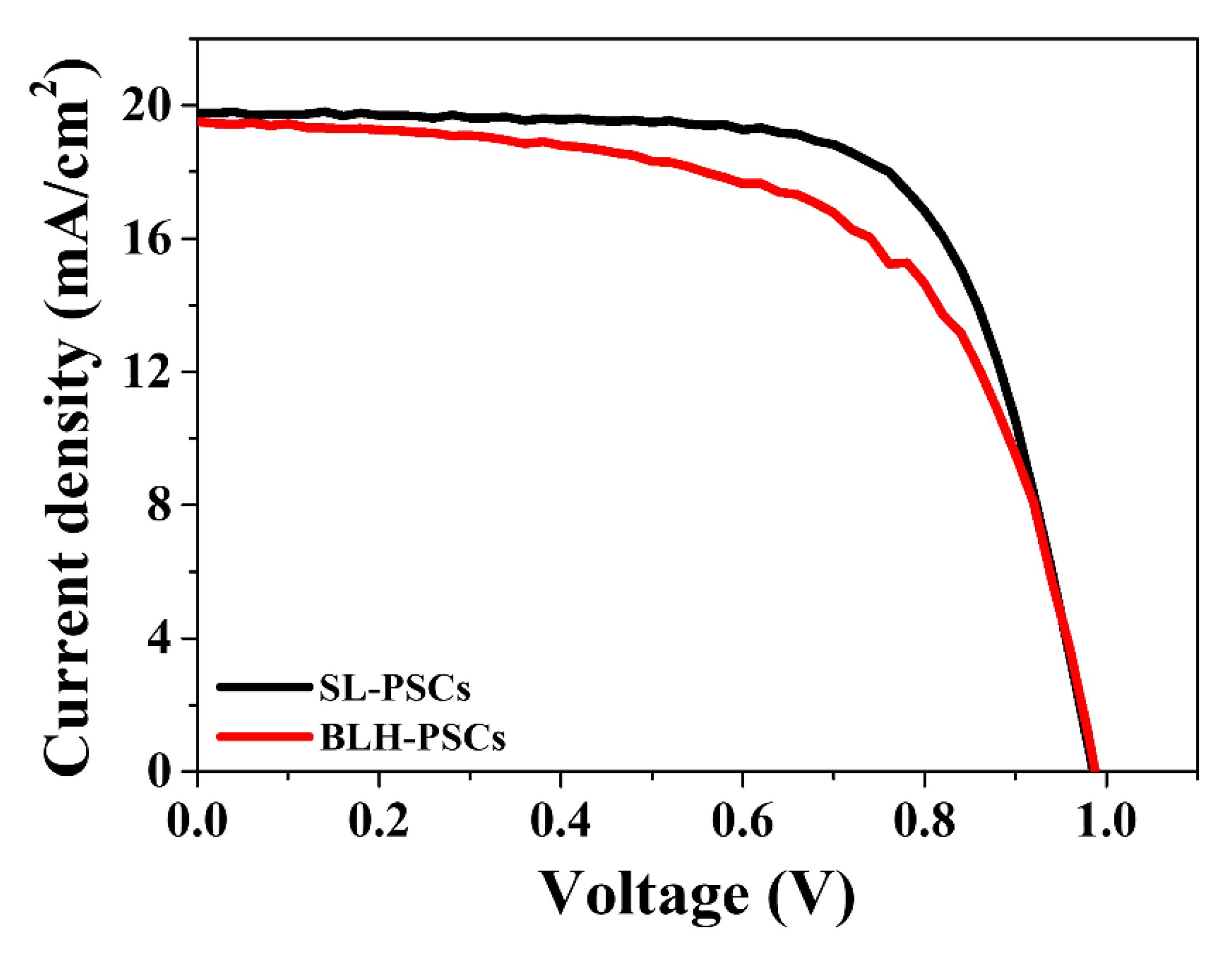
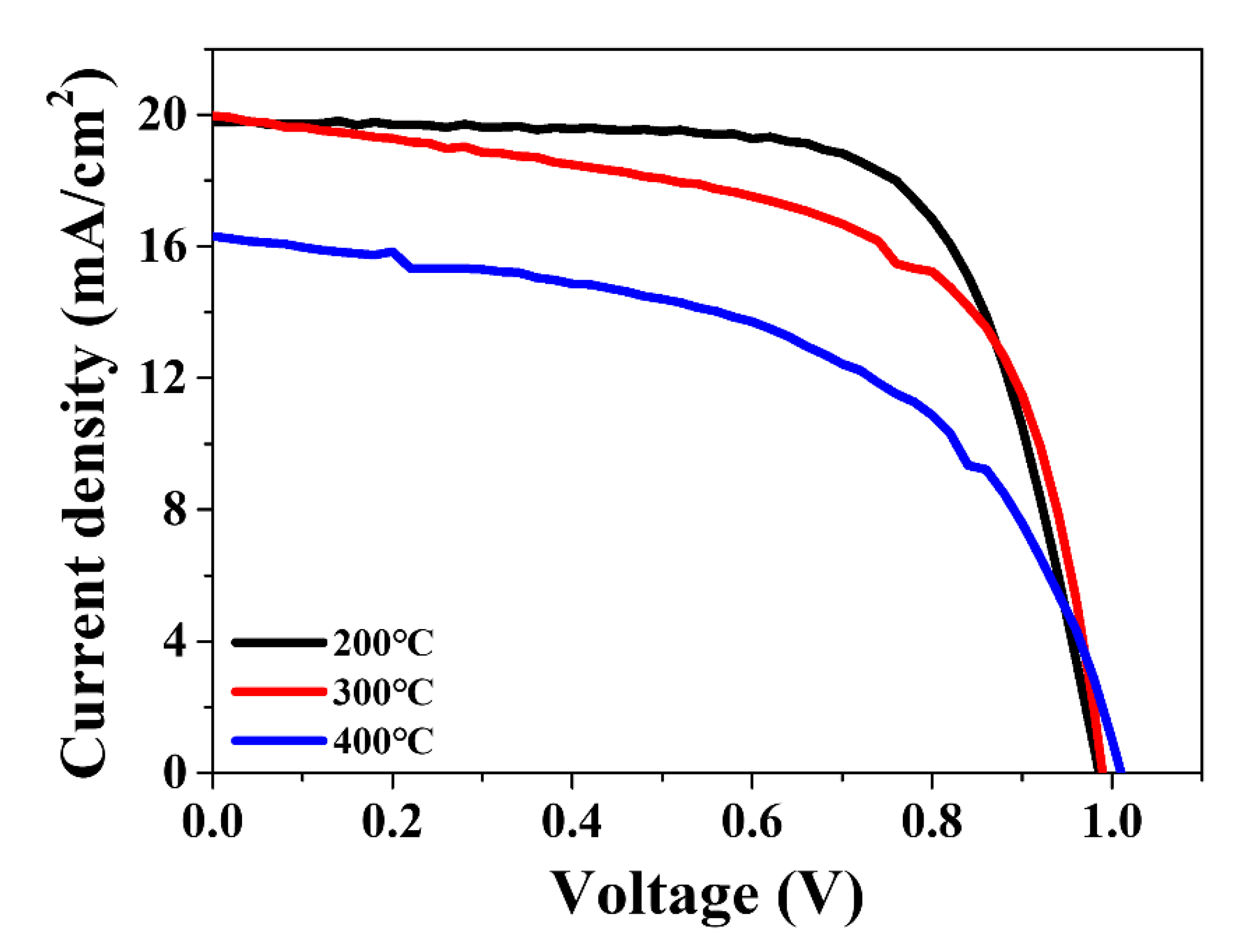
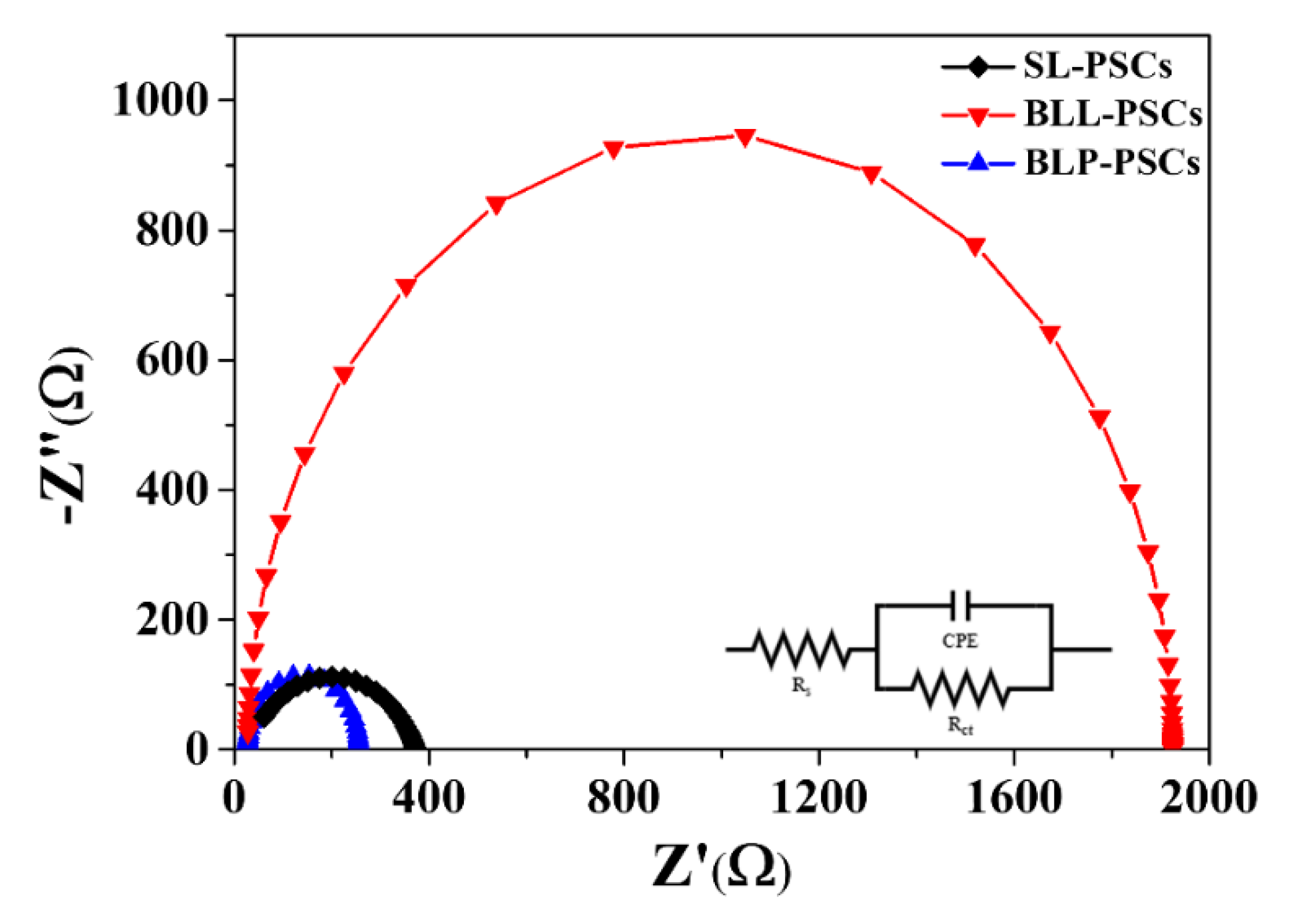
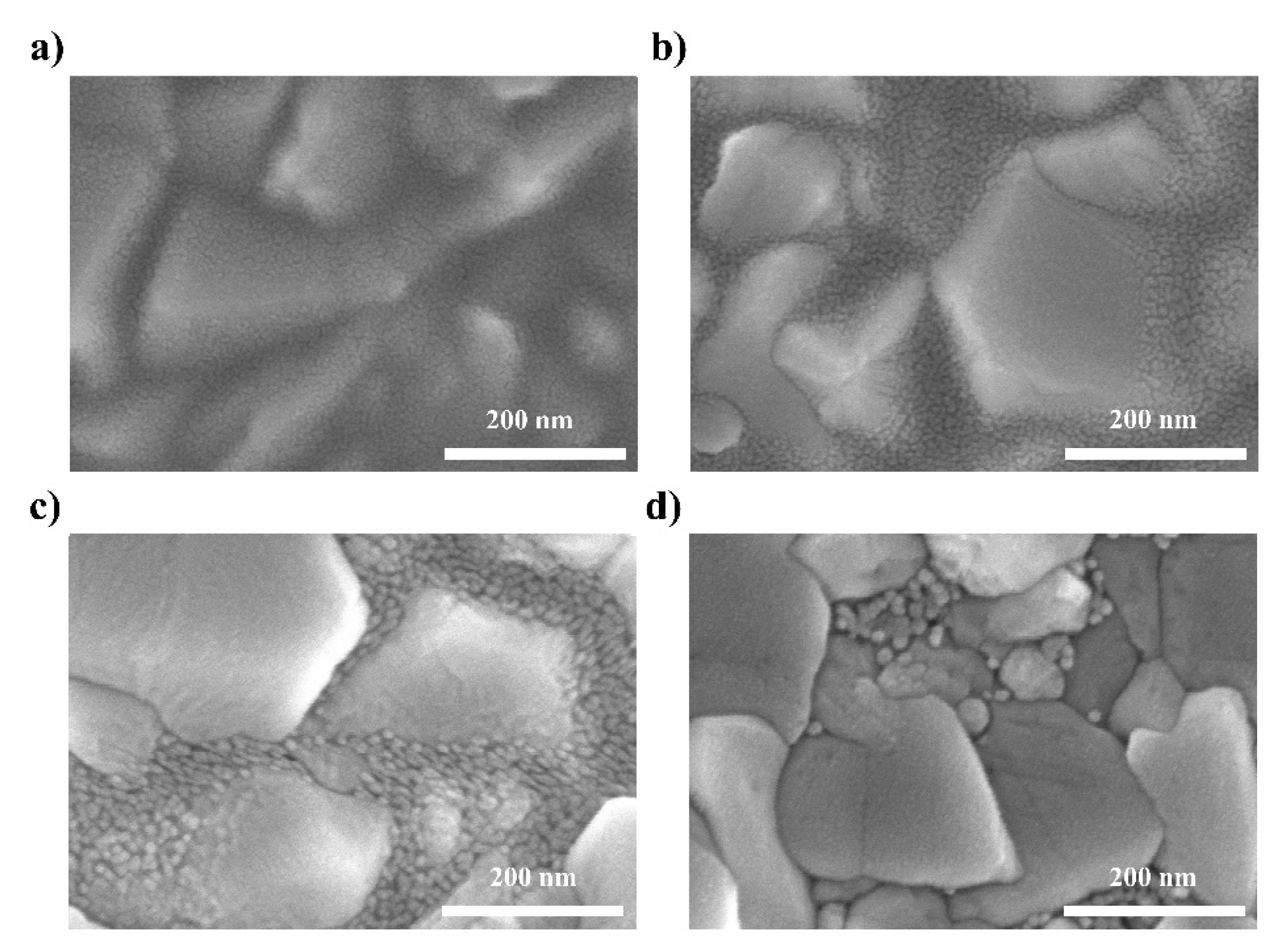
3. Results and Discussion

To investigate the possibility of using the conventional high-temperature-processed m-TiO2 layer as the layer combined with the c-SnO2 layer, we performed a comparative study of PSCs using both planar- and mesoporous-type PSCs. SL-PSCs in the configuration of FTO/c-SnO2/perovskite/spiro-OMeTAD/Ag and BLH-PSCs in the configuration of FTO/c-SnO2/m-TiO2/spiro-OMeTAD/Ag were fabricated. In the case of the BLH-PSCs, the m-TiO2 layer was sintered at 450 °C after spin-coating on the SnO2 layer. The current density–voltage (J-V) curves under an irradiation of 100 mW cm−2 (AM 1.5) are shown in Figure 1. The SL-PSCs achieved a PCE of 13.68% with an open-circuit voltage (VOC) of 0.99 V, a short-circuit current density (JSC) of 19.77 mA/cm2, and a fill factor (FF) of 70.22%. In contrast, the BLH-PSCs only achieved a PCE of 11.93% with a VOC of 0.99 V, a JSC of 19.52 mA/cm2, and an FF of 61.86%. It is thus clear that SL-PSCs perform much better than BLH-PSCs. The large difference in FF could be primary attributed to the degradation of the SnO2 layer by the high-temperature process [22].
To uncover the underlying reasons for the decreased photovoltaic performance of BLH-PSCs, we fabricated SL-PSCs using a SnO2 ETL annealed at temperatures from 200–500 °C. Figure 2 shows the dependence of PCE on the annealing temperature of the SnO2 layer. As the annealing temperature increased, the photovoltaic performance of SL-PSCs decreased. The PECs of SL-PSCs annealed at 200, 300, and 400 °C were 13.68%, 12.19%, and 8.90%, respectively. The SL-PSCs annealed at 400 °C performed poorly, with very low FF and JSC. Moreover, the SL-PSCs annealed at 500 °C did not show any photovoltaic characteristics. The detailed photovoltaic parameters obtained from the J-V curves are summarized in Table S1.
To verify the decreasing trend in PCE, we investigated the morphology change of the SnO2 layer according to the annealing temperature. Figure 3 shows the top-view SEM images of SnO2 layers deposited on FTO substrates and annealed at different temperatures. As shown in Figure 3a, the FTO substrate was uniformly covered with the SnO2 layer, and no pinholes were observed when the SnO2 layer was annealed at the relatively low temperature of 200 °C. However, as the annealing temperature increased above 300 °C, the SnO2 nanoparticles agglomerated more and the FTO areas uncovered by SnO2 increased. The high-temperature-annealed SnO2 layer could not completely cover the FTO substrate, and thus these pinholes resulted in leakage in the current pathway. Moreover, poor interface contact with the FTO substrate increased the series resistance. Therefore, as shown in Figure 1, BLH-PSCs exhibited lower FF and PCE than SL-PSCs because the high-temperature process of the m-TiO2 layer caused the degradation of the underlying SnO2 layer [24]. The above results confirm that the low-temperature processing of the m-TiO2 layer without causing damage to the SnO2 layer is important for producing high-performance PSCs using a c-SnO2/m-TiO2 bilayer ETL.
To investigate the effectiveness of our strategy for LT m-TiO2, we compared the PCEs of three different PSCs (Figure S2). First, we fabricated SL-PSC without the m-TiO2 layer to determine the role of the m-TiO2 layer. Then, we fabricated two different PSCs based on the FTO/c-SnO2/m-TiO2/spiro-OMeTAD/Ag architecture. The main difference between these two PSCs with a bilayer ETL was the post-treatment of the m-TiO2 layer. In the case of LT m-TiO2-based PSCs (BLL-PSCs), the m-TiO2 layers were only annealed at 150 °C, whereas oxygen plasma treatment was directly performed on the LT TiO2 layers for BLP-PSCs. As shown in Figure 4, the BLL-PSCs exhibited a PCE of only 5.43% with a VOC of 0.85 V, a JSC of 14.81 mA/cm2, and an FF of 43.01% (Table 1). Although the low-temperature processing of m-TiO2 might not have caused the aggregation of the underlying c-SnO2 layer, the remaining organic additives in m-TiO2 inhibited the full coverage of the perovskite layer on TiO2, which hindered electron transport at the interface between the perovskite and TiO2. According to our previous work, oxygen plasma treatment can successfully remove organic additives from and improve the wettability of the LT TiO2 layer [13]. With oxygen plasma treatment, the performance of BLL-PSCs considerably improved, and the PCE, VOC, JSC, and FF were 15.35%, 1.03 V, 20.65 mA/cm2, and 72.30%, respectively. Moreover, the PCE of BLP-PSC (15.53%) is higher than that of SL-PSC (13.68%). These results demonstrate that oxygen plasma treatment enables the fabrication of c-SnO2/m-TiO2 bilayer ETL-based PSCs with excellent photovoltaic performance using an LT m-TiO2 layer.
To gain further insight into the effects of the m-TiO2 layer on charge transfer properties at the ETL/perovskite interface, EIS was conducted. The Nyquist plots of different ETLs were obtained in the dark with an applied bias voltage of 0.9 V and are shown in Figure 5. The series resistance (Rs) and charge transport resistance (Rct) were obtained by fitting EIS data according to the relevant equivalent circuit, as shown in the inset of Figure 5. The EIS parameters from the semicircle Nyquist plot are summarized in Table S2. In general, Rs is related to the sheet resistance of electrodes [25], including the contributions from FTO and metal electrodes. In contrast, Rct generally refers to the charge transfer resistance at all the interfaces [26], such as between the carrier selective layer and the perovskite layer, and between the electrode and the carrier selective layer. The Rct value of SL-PSC was 350 Ω, which is slightly higher than that of BLP-PSC (230 Ω). The small Rct value of BLP-PSC further supports that the combination of the m-TiO2 layer with c-SnO2 promotes good interface contact between the ETL and perovskite, leading to an enhanced charge transfer process and the highest PCE [27]. While BLL-PSC exhibited the highest value of Rct, it had the lowest PCE. Figure S1 shows the top-view SEM images of the perovskite layer on c-SnO2 and c-SnO2/m-TiO2 and their corresponding grain size distribution histograms. Both perovskite layers exhibited a similar average grain size with uniform morphology consisting of densely packed grains. Because the grain size, which refers to the density of grain boundaries, is related to the transport of photogenerated carriers and the extension of the charge carrier diffusion length [28], a comparable grain size might not result in different photovoltaic characteristics. However, the mesoporous structure of TiO2 allows the perovskite to infiltrate into TiO2, which increases the interfacial contact between perovskite and TiO2 (Figure S3). Therefore, the improved interfacial contact due to the direct transfer pathway substantially contributed to the increase in PCE of SL-PSCs by combination with the m-TiO2 ETL (Figure S4 and Table S3).
The high performance of c-SnO2/m-TiO2 bilayer ETL-based PSCs was achieved with oxygen plasma treatment at a low temperature, which suggests that high-performance and flexible BLP-PSCs can also be attained via the same procedures. Figure 6 shows the J-V curves of the flexible BLP-PSCs constructed on the PEN/ITO substrate as a function of bending cycles. The flexible cells exhibited a promising PCE of 9.56%, with a VOC of 1.81 V, a JSC of 17.20 mA/cm2, and an FF of 55.22%. The inferior performance of the flexible cell compared to the rigid cell on the FTO/glass substrate arose from its inferior surface morphology and low transmittance compared to the rigid surface [29]. To investigate the mechanical stability of the flexible cell, a bending durability test was performed. All the photovoltaic characteristics were maintained during 500 cycles of bending without much deterioration.

4. Conclusions

In summary, an LT m-TiO2 layer using oxygen plasma treatment was combined with c-SnO2. The BLP-PSC had a PCE of 15.36%, which is much higher than that of the PSC with a single c-SnO2 ETL. This high efficiency was obtained because the oxygen plasma treatment facilitated the removal of organic additives from LT m-TiO2 and the infiltration of perovskite into m-TiO2, thus enhancing charge transport and extraction. This proves that our strategy to construct a bilayer ETL using LT m-TiO2 is beneficial because it allows the superior characteristics of the underlying c-SnO2 to be maintained, and the mesoporous structure provided increased interfacial contact between the perovskite and the ETL. Consequently, the c-SnO2/m-TiO2 bilayer ETL is thought to be one of the most promising ETL layers for high-efficiency PSCs.

Supplementary Materials

The following supporting information can be downloaded at: https://www.mdpi.com/article/10.3390/nano12040718/s1, Figure S1: Top-view SEM images and grain size distribution histograms (inset) of MAPbI3 layer on SL, BLL, BLP, and BLH; Figure S2: XRD pattern of MAPbI3 layer on BLP, BLL, and SL; Figure S3: Cross-section SEM image of glass/FTO/ETL/MAPbI3; Figure S4: Reverse scan (solid line) and forward scan (dotted line) current density–voltage curves of PSCs based on SL-PSC, BLL-PSC, and BLP-PSC; Table S1: Summary of the photovoltaic parameters of PSCs based on SnO2 ETL annealed at 200, 300, and 400 °C; Table S2: Summary of EIS data; Table S3: Summary of the photovoltaic parameters of SL-PSC, BLL-PSC, and BLP-PSC according to scan direction.

Author Contributions

S.J. conceived and designed the research; J.L. participated in material preparation and device fabrication; J.K. and C.-S.K. participated in data interpretation; S.J. and J.L. wrote the paper; S.J. supervised the project. All authors have read and agreed to the published version of the manuscript.

Funding

This work was supported by the National Research Foundation (NRF) grant funded by the Korea government (MSIT) (2020R1F1A1074743 and 2021R1A4A1031761).

Institutional Review Board Statement

Not applicable.

Data Availability Statement

The data presented in this article is available on request from the corresponding author.

Conflicts of Interest

The authors declare no conflict of interest.

References

  1. Yoo, J.J.; Seo, G.; Chua, M.R.; Park, T.G.; Lu, Y.; Rotermund, F.; Kim, Y.-K.; Moon, C.S.; Jeon, N.J.; Correa-Baena, J.-P.; et al. Efficient perovskite solar cells via improved carrier management. Nature 2021, 590, 587–593. [Google Scholar] [CrossRef]
  2. Green, M.; Dunlop, E.; Hohl-Ebinger, J.; Yoshita, M.; Kopidakis, N.; Hao, X. Solar cell efficiency tables (version 57). Prog. Photovoltaics: Res. Appl. 2021, 29, 3–15. [Google Scholar] [CrossRef]
  3. Hu, Y.; Niu, T.; Liu, Y.; Zhou, Y.; Xia, Y.; Ran, C.; Wu, Z.; Song, L.; Müller-Buschbaum, P.; Chen, Y.; et al. Flexible Perovskite Solar Cells with High Power-Per-Weight: Progress, Application, and Perspectives. ACS Energy Lett. 2021, 6, 2917–2943. [Google Scholar] [CrossRef]
  4. Ma, S.; Yuan, G.-Z.; Zhang, Y.; Yang, N.; Li, Y.; Chen, Q. Development of encapsulation strategies towards the commercialization of perovskite solar cells. Energy Environ. Sci. 2021, 15, 13–55. [Google Scholar] [CrossRef]
  5. Dai, T.; Cao, Q.; Yang, L.; Aldamasy, M.; Li, M.; Liang, Q.; Lu, H.; Dong, Y.; Yang, Y. Strategies for High-Performance Large-Area Perovskite Solar Cells toward Commercialization. Crystals 2021, 11, 295. [Google Scholar] [CrossRef]
  6. Cai, L.; Liang, L.; Wu, J.; Ding, B.; Gao, L.; Fan, B. Large area perovskite solar cell module. J. Semicond. 2017, 38, 014006. [Google Scholar] [CrossRef]
  7. Park, N.-G. Perovskite solar cells: An emerging photovoltaic technology. Mater. Today 2015, 18, 65–72. [Google Scholar] [CrossRef]
  8. Noh, M.F.M.; Teh, C.H.; Daik, R.; Lim, E.L.; Yap, C.C.; Ibrahim, M.A.; Ludin, N.A.; Yusoff, A.R.B.M.; Jang, J.; Teridi, M.A.M. The architecture of the electron transport layer for a perovskite solar cell. J. Mater. Chem. C 2018, 6, 682–712. [Google Scholar] [CrossRef]
  9. Anaraki, E.H.; Kermanpur, A.; Steier, L.; Domanski, K.; Matsui, T.; Tress, W.; Saliba, M.; Abate, A.; Grätzel, M.; Hagfeldt, A.; et al. Highly efficient and stable planar perovskite solar cells by solution-processed tin oxide. Energy Environ. Sci. 2016, 9, 3128–3134. [Google Scholar] [CrossRef]
  10. Tiwana, P.; Docampo, P.; Johnston, M.B.; Snaith, H.J.; Herz, L.M. Electron Mobility and Injection Dynamics in Mesoporous ZnO, SnO2, and TiO2 Films Used in Dye-Sensitized Solar Cells. ACS Nano 2011, 5, 5158–5166. [Google Scholar] [CrossRef]
  11. Min, H.; Lee, D.Y.; Kim, J.; Kim, G.; Lee, K.S.; Kim, J.; Il Seok, S.; Paik, M.J.; Kim, Y.K.; Kim, K.S.; et al. Perovskite solar cells with atomically coherent interlayers on SnO2 electrodes. Nature 2021, 598, 444–450. [Google Scholar] [CrossRef]
  12. Xiong, L.; Guo, Y.; Wen, J.; Liu, H.; Yang, G.; Qin, P.; Fang, G. Review on the Application of SnO2 in Perovskite Solar Cells. Adv. Funct. Mater. 2018, 28, 1802757. [Google Scholar] [CrossRef]
  13. Nam, J.; Kim, J.-H.; Kim, C.S.; Kwon, J.-D.; Jo, S. Surface Engineering of Low-Temperature Processed Mesoporous TiO2 via Oxygen Plasma for Flexible Perovskite Solar Cells. ACS Appl. Mater. Interfaces 2020, 12, 12648–12655. [Google Scholar] [CrossRef]
  14. Song, J.; Zheng, E.; Wang, X.-F.; Tian, W.; Miyasaka, T. Low-temperature-processed ZnO–SnO2 nanocomposite for efficient planar perovskite solar cells. Sol. Energy Mater. Sol. Cells 2016, 144, 623–630. [Google Scholar] [CrossRef] [Green Version]
  15. Ma, J.; Yang, G.; Qin, M.; Zheng, X.; Lei, H.; Chen, C.; Chen, Z.; Guo, Y.; Han, H.; Zhao, X.; et al. MgO Nanoparticle Modified Anode for Highly Efficient SnO2 -Based Planar Perovskite Solar Cells. Adv. Sci. 2017, 4, 1700031. [Google Scholar] [CrossRef]
  16. Han, G.S.; Chung, H.S.; Kim, D.H.; Kim, B.J.; Lee, J.-W.; Park, N.-G.; Cho, I.S.; Lee, J.-K.; Lee, S.; Jung, H.S. Epitaxial 1D electron transport layers for high-performance perovskite solar cells. Nanoscale 2015, 7, 15284–15290. [Google Scholar] [CrossRef]
  17. Kogo, A.; Ikegami, M.; Miyasaka, T. A SnOx–brookite TiO2 bilayer electron collector for hysteresis-less high efficiency plastic perovskite solar cells fabricated at low process temperature. Chem. Commun. 2016, 52, 8119–8122. [Google Scholar] [CrossRef]
  18. Tang, H.; Cao, Q.; He, Z.; Wang, S.; Han, J.; Li, T.; Gao, B.; Yang, J.; Deng, D.; Li, X. SnO2–Carbon Nanotubes Hybrid Electron Transport Layer for Efficient and Hysteresis-Free Planar Perovskite Solar Cells. Sol. RRL 2020, 4, 1900415. [Google Scholar] [CrossRef]
  19. Yang, G.; Wang, C.; Lei, H.; Zheng, X.; Qin, P.; Xiong, L.; Zhao, X.; Yan, Y.; Fang, G. Interface engineering in planar perovskite solar cells: Energy level alignment, perovskite morphology control and high performance achievement. J. Mater. Chem. A 2017, 5, 1658–1666. [Google Scholar] [CrossRef]
  20. Xiong, Z.; Lan, L.; Wang, Y.; Lu, C.; Qin, S.; Chen, S.; Zhou, L.; Zhu, C.; Li, S.; Meng, L.; et al. Multifunctional Polymer Framework Modified SnO2 Enabling a Photostable α-FAPbI3 Perovskite Solar Cell with Efficiency Exceeding 23%. ACS Energy Lett. 2021, 6, 3824–3830. [Google Scholar] [CrossRef]
  21. Kogo, A.; Sanehira, Y.; Numata, Y.; Ikegami, M.; Miyasaka, T. Amorphous Metal Oxide Blocking Layers for Highly Efficient Low-Temperature Brookite TiO2-Based Perovskite Solar Cells. ACS Appl. Mater. Interfaces 2018, 10, 2224–2229. [Google Scholar] [CrossRef]
  22. Jung, K.-H.; Seo, J.-Y.; Lee, S.; Shin, H.; Park, N.-G. Solution-processed SnO2thin film for a hysteresis-free planar perovskite solar cell with a power conversion efficiency of 19.2%. J. Mater. Chem. A 2017, 5, 24790–24803. [Google Scholar] [CrossRef]
  23. Nam, J.; Nam, I.; Song, E.-J.; Kwon, J.-D.; Kim, J.; Kim, C.S.; Jo, S. Facile Interfacial Engineering of Mesoporous TiO2 for Low-Temperature Processed Perovskite Solar Cells. Nanomaterials 2019, 9, 1220. [Google Scholar] [CrossRef] [Green Version]
  24. Parida, B.; Singh, A.; Oh, M.; Jeon, M.; Kang, J.-W.; Kim, H. Effect of compact TiO2 layer on structural, optical, and performance characteristics of mesoporous perovskite solar cells. Mater. Today Commun. 2019, 18, 176–183. [Google Scholar] [CrossRef]
  25. Bu, T.; Wu, L.; Liu, X.; Yang, X.; Zhou, P.; Yu, X.; Qin, T.; Shi, J.; Wang, S.; Li, S.; et al. Synergic Interface Optimization with Green Solvent Engineering in Mixed Perovskite Solar Cells. Adv. Energy Mater. 2017, 7, 1700576. [Google Scholar] [CrossRef]
  26. Chen, C.; Jiang, Y.; Guo, J.; Wu, X.; Zhang, W.; Wu, S.; Gao, X.; Hu, X.; Wang, Q.; Zhou, G.; et al. Solvent-Assisted Low-Temperature Crystallization of SnO2 Electron-Transfer Layer for High-Efficiency Planar Perovskite Solar Cells. Adv. Funct. Mater. 2019, 29, 1900557. [Google Scholar] [CrossRef]
  27. Li, M.; Wang, Z.-K.; Yang, Y.-G.; Hu, Y.; Feng, S.-L.; Wang, J.-M.; Gao, X.-Y.; Liao, L.-S. Copper Salts Doped Spiro-OMeTAD for High-Performance Perovskite Solar Cells. Adv. Energy Mater. 2016, 6, 1601156. [Google Scholar] [CrossRef]
  28. Hidayat, R.; Nurunnizar, A.A.; Fariz, A.; Herman; Rosa, E.S.; Shobih; Oizumi, T.; Fujii, A.; Ozaki, M. Revealing the charge carrier kinetics in perovskite solar cells affected by mesoscopic structures and defect states from simple transient photovoltage measurements. Sci. Rep. 2020, 10, 19197. [Google Scholar] [CrossRef] [PubMed]
  29. Huang, K.; Peng, Y.; Gao, Y.; Shi, J.; Li, H.; Mo, X.; Huang, H.; Gao, Y.; Ding, L.; Yang, J. High-Performance Flexible Perovskite Solar Cells via Precise Control of Electron Transport Layer. Adv. Energy Mater. 2019, 9, 1901419. [Google Scholar] [CrossRef]
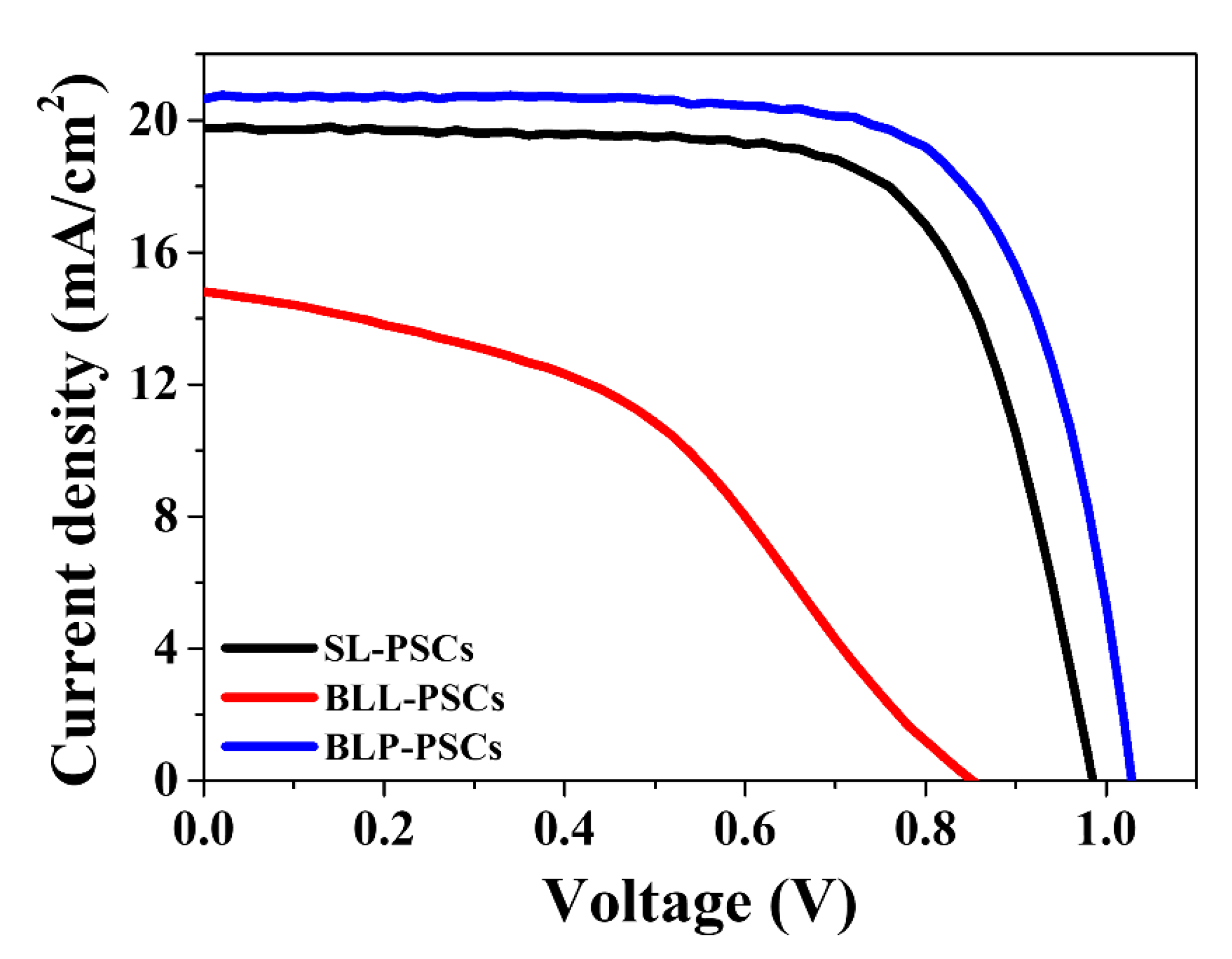
Figure 1. Reverse scan current density–voltage (J-V) curves of SL-PSC and BLH-PSC.
Nanomaterials 12 00718 g001
Figure 2. Reverse scan current density–voltage (J-V) curves of perovskite solar cells based on SnO2 ETL annealed at 200, 300, and 400 °C.
Nanomaterials 12 00718 g002
Figure 3. Top SEM image of SnO2 layer after annealing at (a) 200, (b) 300, (c) 400, and (d) 500 °C on FTO glass.
Nanomaterials 12 00718 g003
Figure 4. Reverse scan current density–voltage (J-V) curves of SL-PSCs, BLL-PSCs, and BLP-PSCs.
Nanomaterials 12 00718 g004
Figure 5. Nyquist plots of SL-PSCs, BLL-PSCs, and BLP-PSCs.
Nanomaterials 12 00718 g005
Figure 6. (a) Reverse scan current density–voltage (J-V) curves of flexible cells and (b) variation in the JSC, VOC, and FF values of flexible cells as a function of bending cycles.
Nanomaterials 12 00718 g006
Table 1. Summary of the photovoltaic parameters of PSCs based on different ETLs.
SampleJSC (mA/cm2)VOC (V)FF (%)PCE (%)
SL-PSCs19.770.9970.2213.68
BLL-PSCs14.810.8543.015.43
BLP-PSCs20.651.0372.3015.36
Publisher’s Note: MDPI stays neutral with regard to jurisdictional claims in published maps and institutional affiliations.

