
Investigation of Autostereoscopic Displays Based on Various Display Technologies


Abstract
:1. Introduction
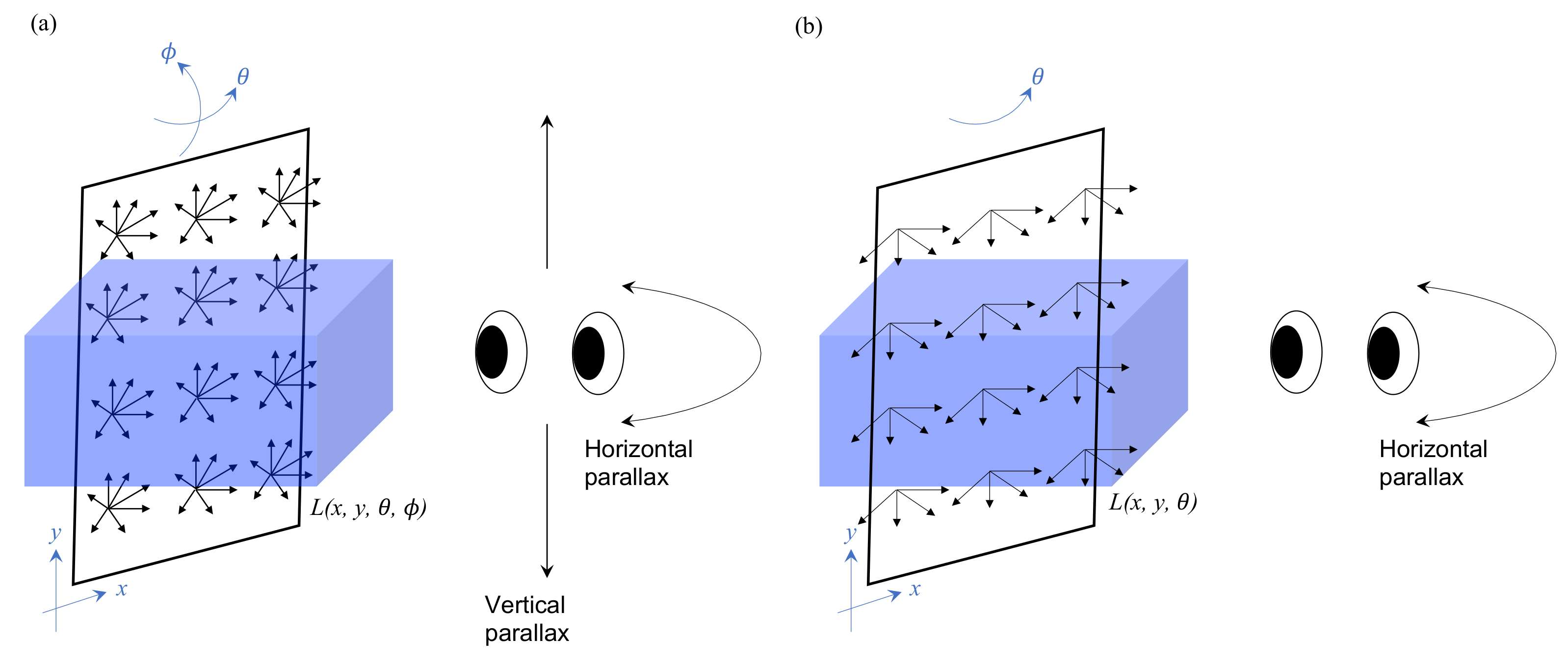
2. Light-Field Displays
3. Spatial Multiplex
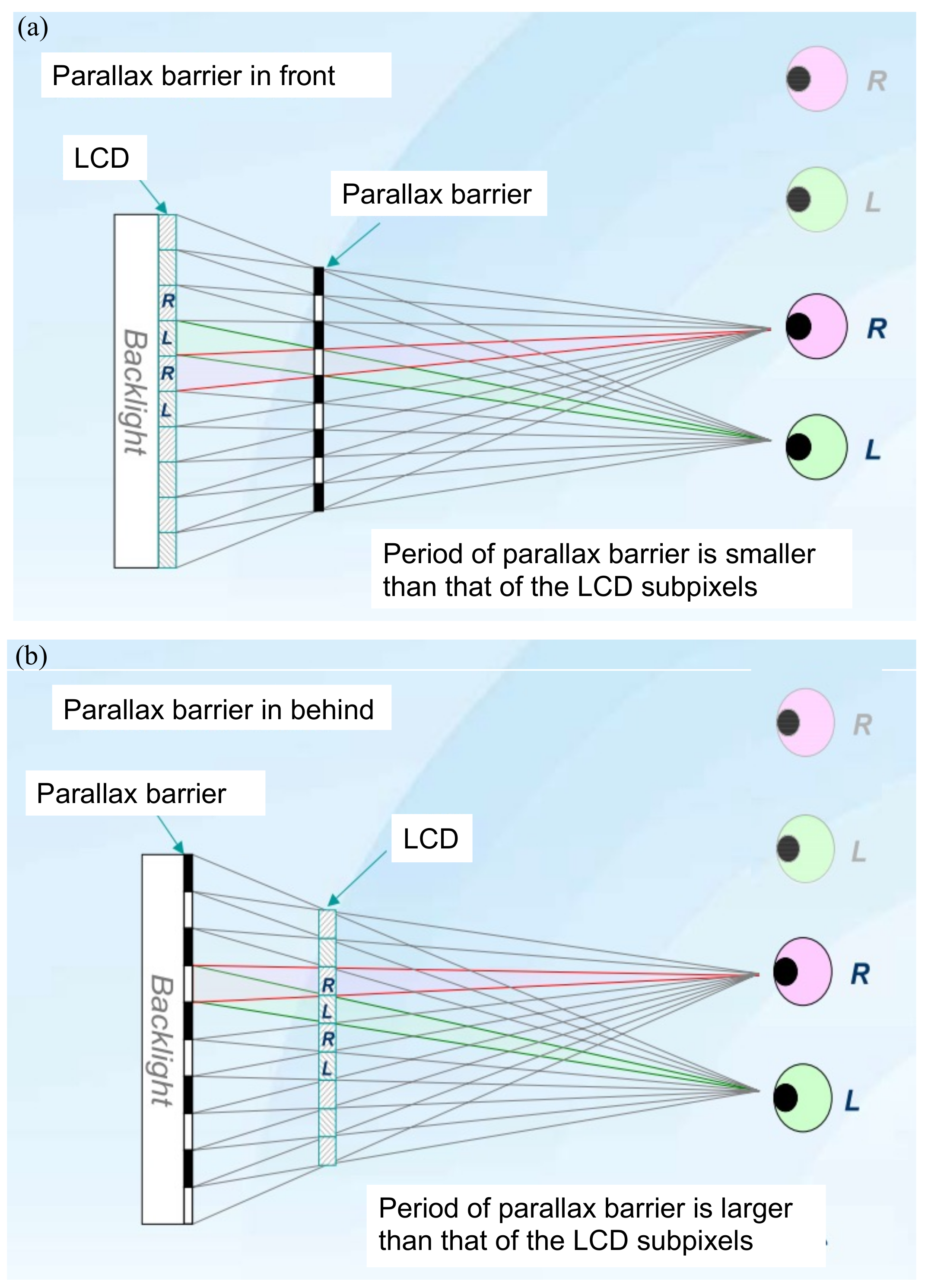
3.1. Parallax Barrier
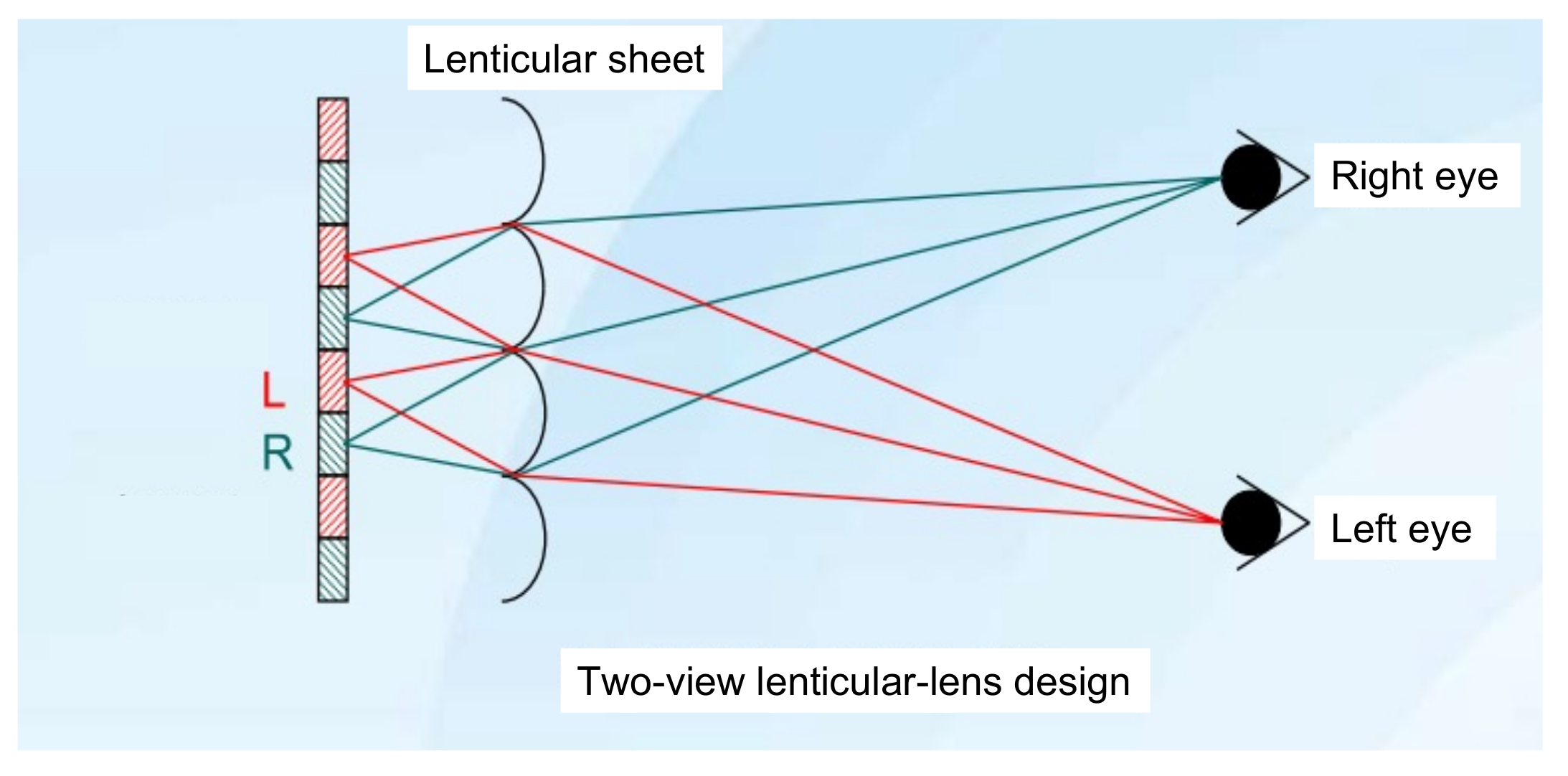
3.2. Lenticular Lenses
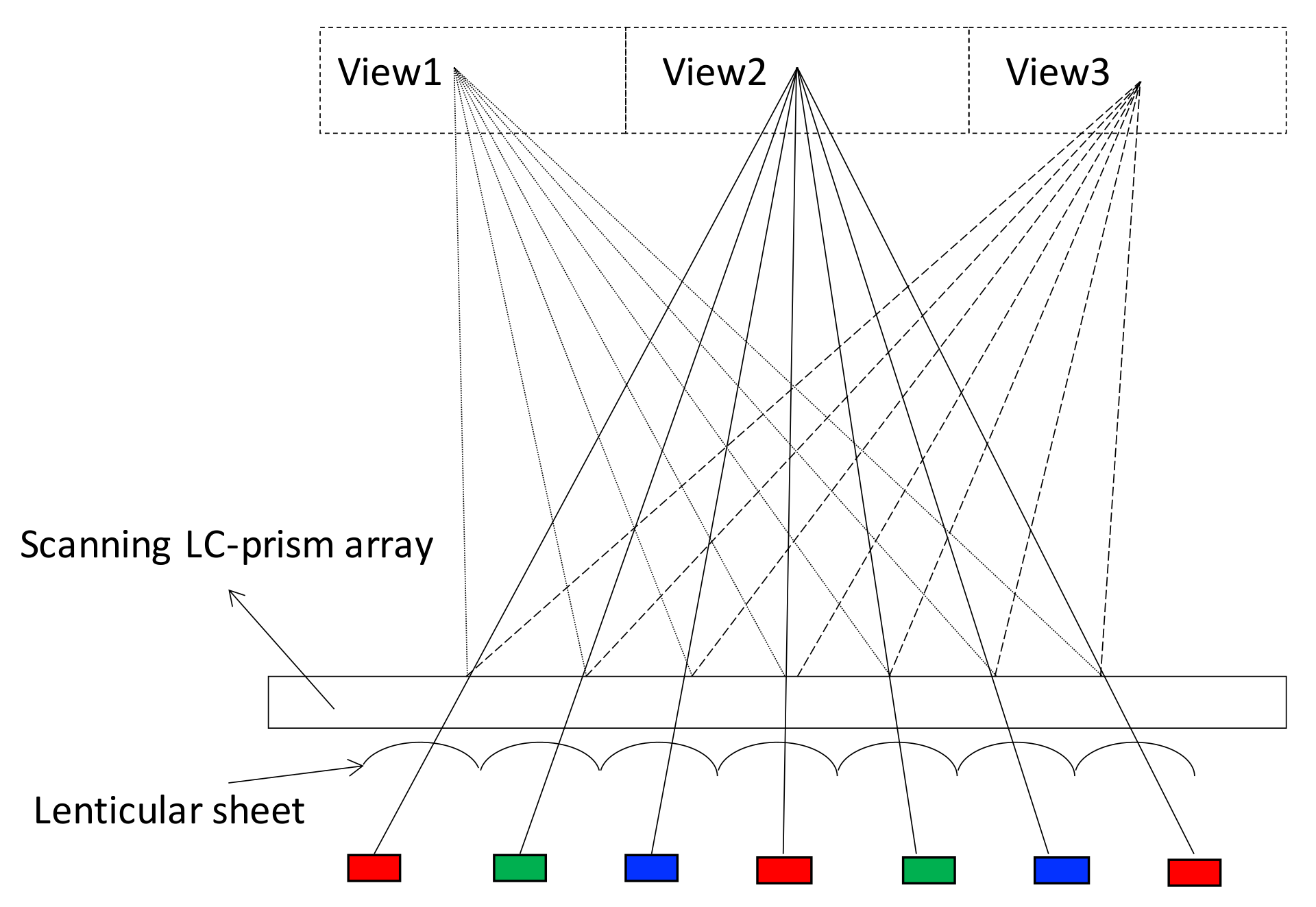
4. Time Multiplex
5. Integral Imaging
6. Electronic Holography
7. Comprehensive Analysis of 3D Display Based on LCD, OLED, and Micro-LED
8. The Future of 3D Display: Micro-LED Plays the Key Role
9. Conclusions
Author Contributions
Funding
Institutional Review Board Statement
Informed Consent Statement
Data Availability Statement
Acknowledgments
Conflicts of Interest
References
- Okoshi, T. Physiology and Psychology of Depth Perception. In Three-Dimensional Imaging Techniques; Okoshi, T., Ed.; Academic Press: Cambridge, MA, USA, 1976; pp. 43–59. [Google Scholar] [CrossRef]
- Geng, J. Three-dimensional display technologies. Adv. Opt. Photonics 2013, 5, 456. [Google Scholar] [CrossRef] [PubMed] [Green Version]
- Ukai, K.; Howarth, P.A. Visual fatigue caused by viewing stereoscopic motion images: Background, theories, and observations. Displays 2008, 29, 106–116. [Google Scholar] [CrossRef]
- Kim, C.Y. New challenges for future 3D TV. In Proceedings of the WIO 2013—12th Workshop on Information Optics, Tenerife, Spain, 15–19 July 2013; pp. 1–3. [Google Scholar] [CrossRef]
- Gershun, A. The Light Field. J. Math. Phys. 1939, 18, 51–151. [Google Scholar] [CrossRef]
- Martínez-Corral, M.; Javidi, B. Fundamentals of 3D imaging and displays: A tutorial on integral imaging, light-field, and plenoptic systems. Adv. Opt. Photonics 2018, 10, 512. [Google Scholar] [CrossRef] [Green Version]
- Levoy, M.; Hanrahan, P. Light field rendering. In Proceedings of the 23rd Annual Conference on Computer Graphics and Interactive Techniques (SIGGRAPH 1996), New York, NY, USA, 8 January 1996; pp. 31–42. [Google Scholar] [CrossRef]
- Ives, F.E. A novel stereogram. J. Frankl. Inst. 1902, 153, 51–52. [Google Scholar] [CrossRef] [Green Version]
- Guo, J.; Diao, Z.; Yan, S.; Zhang, E.; Kong, L. Immersive autostereoscopic display based on curved screen and parallax barrier. Chin. Opt. Lett. 2021, 19, 013301. [Google Scholar] [CrossRef]
- Zhao, W.X.; Wang, Q.H.; Wang, A.H.; Li, D.H. Autostereoscopic display based on two-layer lenticular lenses. Opt. Lett. 2010, 35, 4127. [Google Scholar] [CrossRef]
- Huang, T.; Han, B.; Zhang, X.; Liao, H. High-performance autostereoscopic display based on the lenticular tracking method. Opt. Express 2019, 27, 20421. [Google Scholar] [CrossRef]
- Bogaert, L.; Meuret, Y.; Roelandt, S.; Avci, A.; De Smet, H.; Thienpont, H. Demonstration of a multiview projection display using decentered microlens arrays. Opt. Express 2010, 18, 26092. [Google Scholar] [CrossRef]
- Yuan, W.; Li, L.H.; Lee, W.B.; Chan, C.Y. Fabrication of Microlens Array and Its Application: A Review. Chin. J. Mech. Eng. (Engl. Ed.) 2018, 31, 16. [Google Scholar] [CrossRef] [Green Version]
- Berthier, A. Images stéréoscopiques de grand format. Cosmos Revue Encyclopédique Hebdomadaire des Progrès des Sciences 1896, 34, 210–227. [Google Scholar]
- Huang, K.C.; Chou, Y.H.; Lin, L.C.; Lin, H.Y.; Chen, F.H.; Liao, C.C.; Chen, Y.H.; Lee, K.; Hsu, W.H. A study of optimal viewing distance in a parallax barrier 3D display. J. Soc. Inf. Disp. 2013, 21, 263–270. [Google Scholar] [CrossRef]
- Harris, M. 3-D without four eyes. IEEE Spectr. 2010, 47, 50–56. [Google Scholar] [CrossRef]
- Jacobs, A.; Mather, J.; Winlow, R.; Montgomery, D.; Jones, G.; Willis, M.; Tillin, M.; Hill, L.; Khazova, M.; Stevenson, H.; et al. 2D/3D switchable displays. Shapu Giho/Sharp Tech. J. 2003, 85, 15–18. [Google Scholar]
- Nam, H.; Lee, J.; Jang, H.; Song, M.; Kim, B. 7.3: Auto-Stereoscopic Swing 3D Display. SID Symp. Dig. Tech. Pap. 2005, 36, 94. [Google Scholar] [CrossRef]
- Kim, K.J.; Kang, H.; Jang, M.K.; Ahn, B.C.; Chung, I.J.; Park, T.S.; Chang, J.W.; Lee, K.I.; Kim, S.T. Development of a 42-in. 2-D/3-D switchable display using multi-view technology for public-information-display applications. J. Soc. Inf. Disp. 2007, 15, 899. [Google Scholar] [CrossRef]
- Hamagishi, G.; Sakata, M.; Mashitani, K.; Inoue, M.; Taima, K.; Oyamada, K.; Kishimoto, S.I. 32.1: Invited Paper: A Display System with 2-D/3-D Compatibility. In SID Symposium Digest of Technical Papers; Blackwell Publishing Ltd.: Oxford, UK, 1998; Volume 29, p. 915. [Google Scholar] [CrossRef]
- Tsai, R.Y.; Tsai, C.H.; Lee, K.; Wu, C.L.; Lin, L.C.D.; Huang, K.C.; Hsu, W.L.; Wu, C.S.; Lu, C.F.; Yang, J.C.; et al. Challenge of 3D LCD displays. In Three-Dimensional Imaging, Visualization, and Display 2009; International Society for Optics and Photonics: Chandigarh, India, 2009; Volume 7329, p. 732903. [Google Scholar] [CrossRef]
- Hess, W. Stereoscopic Picture. 1915. Available online: https://en.wikipedia.org/wiki/Autostereoscopy (accessed on 16 December 2021).
- Dekker, T.; De Zwart, S.T.; Ijzerman, W.L. 2D/3D switchable displays. Proc. Int. Meet. Inf. Disp. 2006, 1, 31–35. [Google Scholar] [CrossRef]
- Woodgate, G.J.; Harrold, J. LP-1: Late-News Poster: High Efficiency Reconfigurable 2D/3D Autostereoscopic Display. SID Symp. Dig. Tech. Pap. 2003, 34, 394. [Google Scholar] [CrossRef]
- Hong, H.K.; Jung, S.M.; Lee, B.J.; Im, H.J.; Shin, H.H. 25.3: Autostereoscopic 2D/3D Switching Display Using Electric-Field-Driven LC Lens (ELC Lens). SID Symp. Dig. Tech. Pap. 2008, 39, 348. [Google Scholar] [CrossRef]
- Chang, Y.C.; Jen, T.H.; Ting, C.H.; Huang, Y.P. High-resistance liquid-crystal lens array for rotatable 2D/3D autostereoscopic display. Opt. Express 2014, 22, 2714. [Google Scholar] [CrossRef] [Green Version]
- Chen, W.L.; Chen, F.H.; Tsai, C.H. 2D/3D Switchable Autostereoscopic Display Using Conventional Lenticular Plate. In Proceedings of the 11th International Meeting on Information Display, Beppu, Japan, 5–7 January 2017; p. 64. [Google Scholar]
- Honda, T.; Kajiki, Y.; Susami, K.; Hamaguchi, T.; Endo, T.; Hatada, T.; Fujii, T. Three-dimensional display technologies satisfying “super multiview condition”. In Three-Dimensional Video and Display: Devices and Systems: A Critical Review; International Society for Optics and Photonics: Chandigarh, India, 2001; Volume 10298, p. 102980B. [Google Scholar] [CrossRef]
- Nakanuma, H.; Kamei, H.; Takaki, Y. Natural 3D display with 128 directional images used for human-engineering evaluation. In Stereoscopic Displays and Virtual Reality Systems XII; International Society for Optics and Photonics: Chandigarh, India, 2005; Volume 5664, p. 28. [Google Scholar] [CrossRef]
- Takaki, Y.; Nago, N. Multi-projection of lenticular displays to construct a 256-view super multi-view display. Opt. Express 2010, 18, 8824. [Google Scholar] [CrossRef] [PubMed]
- Kikuta, K.; Takaki, Y. Development of SVGA resolution 128-directional display. In Stereoscopic Displays and Virtual Reality Systems XIV; International Society for Optics and Photonics: Chandigarh, India, 2007; Volume 6490, p. 64900U. [Google Scholar] [CrossRef]
- Takaki, Y.; Dairiki, T. 72-directional display having VGA resolution for high-appearance image generation. In Stereoscopic Displays and Virtual Reality Systems XIII; International Society for Optics and Photonics: Chandigarh, India, 2006; Volume 6055, p. 60550X. [Google Scholar] [CrossRef]
- Takaki, Y. Multi-view 3-D display employing a flat-panel display with slanted pixel arrangement. J. Soc. Inf. Disp. 2010, 18, 476. [Google Scholar] [CrossRef]
- Kanebako, T.; Takaki, Y. Time-multiplexing display module for high-density directional display. In Stereoscopic Displays and Applications XIX; International Society for Optics and Photonics: Chandigarh, India, 2008; Volume 6803, p. 68030P. [Google Scholar] [CrossRef]
- Inoue, N.; Kawakita, M.; Yamamoto, K. 200-Inch Glasses-Free 3D Display and Electronic Holography Being Developed at NICT; IEEE: Piscataway, NJ, USA, 2013; pp. 1–2. [Google Scholar] [CrossRef]
- Chen, W.L.; Tsai, C.H.; Wu, C.S.; Chen, C.Y.; Cheng, S.C. A high-resolution autostereoscopic display system with a wide viewing angle using an LCOS projector array. J. Soc. Inf. Disp. 2010, 18, 647. [Google Scholar] [CrossRef]
- Takaki, Y.; Uchida, S. Table screen 360-degree three-dimensional display using a small array of high-speed projectors. Opt. Express 2012, 20, 8848. [Google Scholar] [CrossRef] [PubMed]
- Aoyama, K.; Yokoyama, K.; Yano, T.; Nakahata, Y. Eye-sensing light field display for spatial reality reproduction. Dig. Tech. Pap. SID Int. Symp. 2021, 52, 669–672. [Google Scholar] [CrossRef]
- Lee, H.J.; Nam, H.; Lee, J.D.; Jang, H.W.; Song, M.S.; Kim, B.S.; Gu, J.S.; Park, C.Y.; Choi, K.H. 8.2: A High Resolution Autostereoscopic Display Employing a Time Division Parallax Barrier. SID Symp. Dig. Tech. Pap. 2006, 37, 81. [Google Scholar] [CrossRef]
- Kim, D.S.; Shestak, S.; Cha, K.H.; Park, S.M.; Hwang, S.D. Time-sequential autostereoscopic OLED display with segmented scanning parallax barrier. In Three-Dimensional Imaging, Visualization, and Display 2009; International Society for Optics and Photonics: Chandigarh, India, 2009; Volume 7329, p. 73290U. [Google Scholar] [CrossRef]
- Gaudreau, J.E. Full-resolution autostereoscopic display using an all-electronic tracking/steering system. In Stereoscopic Displays and Applications XXIII; International Society for Optics and Photonics: Chandigarh, India, 2012; Volume 8288, p. 82881Z. [Google Scholar] [CrossRef]
- Schultz, J.C.; Brott, R.; Sykora, M.; Bryan, W.; Fukamib, T.; Nakao, K.; Takimoto, A. 11.5L: Late-News Paper: Full Resolution Autostereoscopic 3D Display for Mobile Applications. SID Symp. Dig. Tech. Pap. 2009, 40, 127. [Google Scholar] [CrossRef]
- Chien, K.W.; Shieh, H.P.; Chu, Y.M.; Tsai, C.Y.; Lin, Y.L.; Hu, C.J.; Chang, C.M.; Hsu, Y.C.; Chen, P.L. Three-Dimensional Display System and Method Thereof. U.S. Patent 7,333,158, 19 February 2008. [Google Scholar]
- Cornelissen, H.J. Display Device with Multi-Grooved Light Direction Element and First and Second Alternating Illuminated Light Sources Simultaneously Switched for 2D Display and Synchronously Switched for 3D Display. U.S. Patent 7,518,663, 14 April 2009. [Google Scholar]
- Chen, F.H.; Tsai, C.H.; Tiao, K.T.; Liou, J.C. Stereoscopic Display. U.S. Patent App. 13/077,987, 2 February 2012. [Google Scholar]
- Lippmann, G. Épreuves réversibles. Photographies intégrales. Comptes Rendus de l’Académie des Sciences 1908, 146, 446–451. [Google Scholar]
- Deng, H.; Wang, Q.H.; Luo, C.G.; Liu, C.L.; Li, C. Accommodation and convergence in integral imaging 3D display. J. Soc. Inf. Disp. 2014, 22, 158–162. [Google Scholar] [CrossRef]
- MacLachlan, C.; Howland, H.C. Normal values and standard deviations for pupil diameter and interpupillary distance in subjects aged 1 month to 19 years. Ophthalmic Physiol. Opt. 2002, 22, 175–182. [Google Scholar] [CrossRef]
- Sang, X.; Fan, F.C.; Jiang, C.C.; Choi, S.; Dou, W.; Yu, C.; Xu, D. Demonstration of a large-size real-time full-color three-dimensional display. Opt. Lett. 2009, 34, 3803–3805. [Google Scholar] [CrossRef] [PubMed]
- Xin Gao, X.G.; Xinzhu Sang, X.S.; Xunbo Yu, X.Y.; Wanlu Zhang, W.Z.; Binbin Yan, B.Y.; Chongxiu Yu, C.Y. 360° light field 3D display system based on a triplet lenses array and holographic functional screen. Chin. Opt. Lett. 2017, 15, 121201. [Google Scholar] [CrossRef]
- Sang, X.; Gao, X.; Yu, X.; Xing, S.; Li, Y.; Wu, Y. Interactive floating full-parallax digital three-dimensional light-field display based on wavefront recomposing. Opt. Express 2018, 26, 8883. [Google Scholar] [CrossRef] [PubMed]
- Ma, X.M.; Xing, Y.; Zheng, J.C.; Li, X.W.; Wang, Q.H. A real-time interactive rendering method for 360° tabletop integral imaging 3D display. J. Soc. Inf. Disp. 2021, 29, 679–688. [Google Scholar] [CrossRef]
- Gabor, D. A new microscopic principle. Nature 1948, 161, 777–778. [Google Scholar] [CrossRef]
- Chen, H.M.P.; Yang, J.P.; Yen, H.T.; Hsu, Z.N.; Huang, Y.; Wu, S.T. Pursuing high quality phase-only liquid crystal on silicon (LCoS) devices. Appl. Sci. 2018, 8, 2323. [Google Scholar] [CrossRef] [Green Version]
- Sugie, T.; Akamatsu, T.; Nishitsuji, T.; Hirayama, R.; Masuda, N.; Nakayama, H.; Ichihashi, Y.; Shiraki, A.; Oikawa, M.; Takada, N.; et al. High-performance parallel computing for next-generation holographic imaging. Nat. Electron. 2018, 1, 254–259. [Google Scholar] [CrossRef]
- Smalley, D.E.; Smithwick, Q.Y.J.; Bove, V.M., Jr. Holographic video display based on guided-wave acousto-optic devices. In Practical Holography XXI: Materials and Applications; International Society for Optics and Photonics: Chandigarh, India, 2007; Volume 6488, p. 64880L. [Google Scholar] [CrossRef]
- Tay, S.; Blanche, P.A.; Voorakaranam, R.; Tunç, A.V.; Lin, W.; Rokutanda, S.; Gu, T.; Flores, D.; Wang, P.; Li, G.; et al. An updatable holographic three-dimensional display. Nature 2008, 451, 694–698. [Google Scholar] [CrossRef]
- Blanche, P.A.; Bablumian, A.; Voorakaranam, R.; Christenson, C.; Lin, W.; Gu, T.; Flores, D.; Wang, P.; Hsieh, W.Y.; Kathaperumal, M.; et al. Holographic three-dimensional telepresence using large-area photorefractive polymer. Nature 2010, 468, 80–83. [Google Scholar] [CrossRef]
- Chen, F.H.; Liao, L.Y.; Chen, C.H.; Tsai, C.H. Binary Holograms for Electro-Holographic Displays. In Digital Holography and Three-Dimensional Imaging; OSA Technical Digest (online); Optical Society of America: Kohala Coast, HI, USA, 2013; p. DTh2A.6. [Google Scholar] [CrossRef]
- Liao, L.Y.; Chen, C.H.; Chen, F.H.; Tsai, C.H.; Liao, E.; Hong, S. Phase-modulation lcos display system with off-axis LED reconstruction light. Dig. Tech. Pap. SID Int. Symp. 2013, 44, 905–908. [Google Scholar] [CrossRef]
- Liou, J.C.; Chen, F.H. Design and fabrication of optical system for time-multiplex autostereoscopic display. Opt. Express 2011, 19, 11007. [Google Scholar] [CrossRef]
- Fattal, D.; Peng, Z.; Tran, T.; Vo, S.; Fiorentino, M.; Brug, J.; Beausoleil, R.G. A multi-directional backlight for a wide-angle, glasses-free three-dimensional display. Nature 2013, 495, 348–351. [Google Scholar] [CrossRef] [PubMed]
- Chen, F.H.; Huang, K.C.; Lin, L.C.; Chou, Y.H.; Lee, K. System crosstalk measurement of a time-sequential 3D display using ideal shutter glasses. In Stereoscopic Displays and Applications XXII; International Society for Optics and Photonics: Chandigarh, India, 2011; Volume 7863, p. 78632E. [Google Scholar] [CrossRef]
- Peng, F.; Huang, Y.; Gou, F.; Hu, M.; Li, J.; An, Z.; Wu, S.T. High performance liquid crystals for vehicle displays. Opt. Mater. Express 2016, 6, 717–726. [Google Scholar] [CrossRef]
- Huang, Y.; Hsiang, E.L.; Deng, M.Y.; Wu, S.T. Mini-LED, Micro-LED and OLED displays: Present status and future perspectives. Light. Sci. Appl. 2020, 9, 105. [Google Scholar] [CrossRef]
- Park, J.S.; Chae, H.; Chung, H.K.; Lee, S.I. Thin film encapsulation for flexible AM-OLED: A review. Semicond. Sci. Technol. 2011, 26, 34001. [Google Scholar] [CrossRef]
- Lee, W.; Shin, Y.; Yoon, J.; Kim, J.; Lee, C.K.; Jeong, Y.; Jang, C.; Hong, J.Y.; Lee, B. Mobile autostereoscopic 3D display using a diamond pixel structured OLED pentile display panel. In Optics InfoBase Conference Papers; OSA Technical Digest (online); Optical Society of America: Seattle, WA, USA, 2014; p. JTu4A.8. [Google Scholar] [CrossRef]
- Kim, J.; Lee, C.K.; Jeong, Y.; Jang, C.; Hong, J.Y.; Lee, W.; Shin, Y.C.; Yoon, J.H.; Lee, B. Crosstalk-reduced dual-mode mobile 3D display. IEEE/OSA J. Disp. Technol. 2015, 11, 97–103. [Google Scholar] [CrossRef]
- Park, J.; Choi, J.H.; Kong, K.; Han, J.H.; Park, J.H.; Kim, N.; Lee, E.; Kim, D.; Kim, J.; Chung, D.; et al. Electrically driven mid-submicrometre pixelation of InGaN micro-light-emitting diode displays for augmented-reality glasses. Nat. Photonics 2021, 15, 449–455. [Google Scholar] [CrossRef]
- Joo, W.J.; Kyoung, J.; Esfandyarpour, M.; Lee, S.H.; Koo, H.; Song, S.; Kwon, Y.N.; Ho Song, S.; Bae, J.C.; Jo, A.; et al. Metasurface-driven OLED displays beyond 10,000 pixels per inch. Science 2020, 370, 459–463. [Google Scholar] [CrossRef]
- Liu, Z.; Lin, C.H.; Hyun, B.R.; Sher, C.W.; Lv, Z.; Luo, B.; Jiang, F.; Wu, T.; Ho, C.H.; Kuo, H.C.; et al. Micro-light-emitting diodes with quantum dots in display technology. Light. Sci. Appl. 2020, 9, 83. [Google Scholar] [CrossRef]
- Deng, Y.; Chu, D. Coherence properties of different light sources and their effect on the image sharpness and speckle of holographic displays. Sci. Rep. 2017, 7, 5893. [Google Scholar] [CrossRef]
- Yen, W.T.; Chen, F.H.; Chen, W.L.; Liou, J.C.; Tsai, C.H. Enhance light efficiency for slim light-strip array backlight on autostereoscopic display. In Proceedings of the 3DTV-Conference: The True Vision-Capture, Transmission and Display of 3D Video (3DTV-CON), Zurich, Switzerland, 15–17 October 2012; pp. 1–4. [Google Scholar] [CrossRef]
- Chen, F.H.; Chen, W.L.; Yen, W.T.; Liou, J.C.; Tsai, C.H. Stereoscopic Display Device. CN103728769B. 2013.
- Peng, D.; Zhang, K.; Chao, V.S.D.; Mo, W.; Lau, K.M.; Liu, Z. Full-color pixelated-addressable light emitting diode on transparent substrate (LEDoTS) micro-displays by CoB. J. Disp. Technol. 2016, 12, 742–746. [Google Scholar] [CrossRef]
- Liang, N. The application of the holographic laser projection in the entertaining performance. In Proceedings of the IEEE International Conference on Advanced Materials for Science and Engineering: Innovation, Science and Engineering (IEEE-ICAMSE 2016), Tainan, Taiwan, 12–13 November 2016; pp. 629–631. [Google Scholar] [CrossRef]


| Type | Pros for 3D Display | Cons for 3D Display |
|---|---|---|
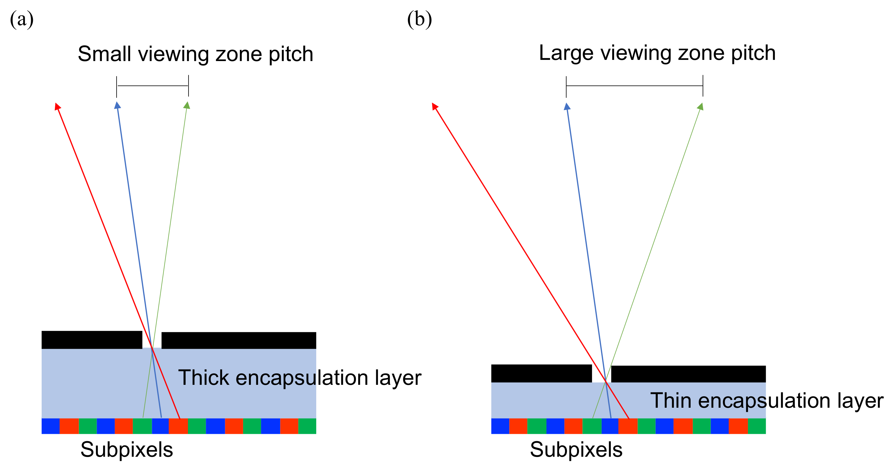
| LCD | 1. LCD is more flexible regarding installation of the light-directional-control element cooperating with the backlight or in front of the color filter. | 1. Slow response time (∼ms), unsuitable for time multiplex. 2. Cover glass is ∼0.5 mm thick, leading to a small viewing zone pitch. 3. Moderate brightness (∼1000 nits), unfavorable for the parallax-barrier setup. |
| OLED | 1. High resolution ∼10,000-ppi compensates for the resolution loss of multiview. 2. Fast response time (∼s), suitable for time-multiplex. 3. Ultra-thin encapsulation layer, leading to a larger viewing zone pitch. | 1. No backlight, the light-directional-control element must be mounted in front of the panel, less flexible setup. 2. Moderate brightness (∼1000 nits), unfavorable for parallax barrier. |
| Micro-LED | 1. High resolution of ∼8500-ppi compensates for the resolution loss of multiview. 2. Fast response time (∼ns), suitable for time multiplex. 3. Ultra-thin encapsulation layer <1 m, leading to a larger viewing zone pitch. 4. High brightness (∼10,000 nits) and low power consumption (6∼7 cd/W) compensates for light loss of the parallax barrier. | 1. No backlight, the light-directional-control element must be mounted in front of the panel, less flexible setup. |
Publisher’s Note: MDPI stays neutral with regard to jurisdictional claims in published maps and institutional affiliations. |
© 2022 by the authors. Licensee MDPI, Basel, Switzerland. This article is an open access article distributed under the terms and conditions of the Creative Commons Attribution (CC BY) license (https://creativecommons.org/licenses/by/4.0/).
Share and Cite
Chen, F.; Qiu, C.; Liu, Z. Investigation of Autostereoscopic Displays Based on Various Display Technologies. Nanomaterials 2022, 12, 429. https://doi.org/10.3390/nano12030429
Chen F, Qiu C, Liu Z. Investigation of Autostereoscopic Displays Based on Various Display Technologies. Nanomaterials. 2022; 12(3):429. https://doi.org/10.3390/nano12030429
Chicago/Turabian StyleChen, Fuhao, Chengfeng Qiu, and Zhaojun Liu. 2022. "Investigation of Autostereoscopic Displays Based on Various Display Technologies" Nanomaterials 12, no. 3: 429. https://doi.org/10.3390/nano12030429
APA StyleChen, F., Qiu, C., & Liu, Z. (2022). Investigation of Autostereoscopic Displays Based on Various Display Technologies. Nanomaterials, 12(3), 429. https://doi.org/10.3390/nano12030429