
Ferroelectric Tuning of ZnO Ultraviolet Photodetectors

Abstract
:1. Introduction
2. Experiments
2.1. Materials
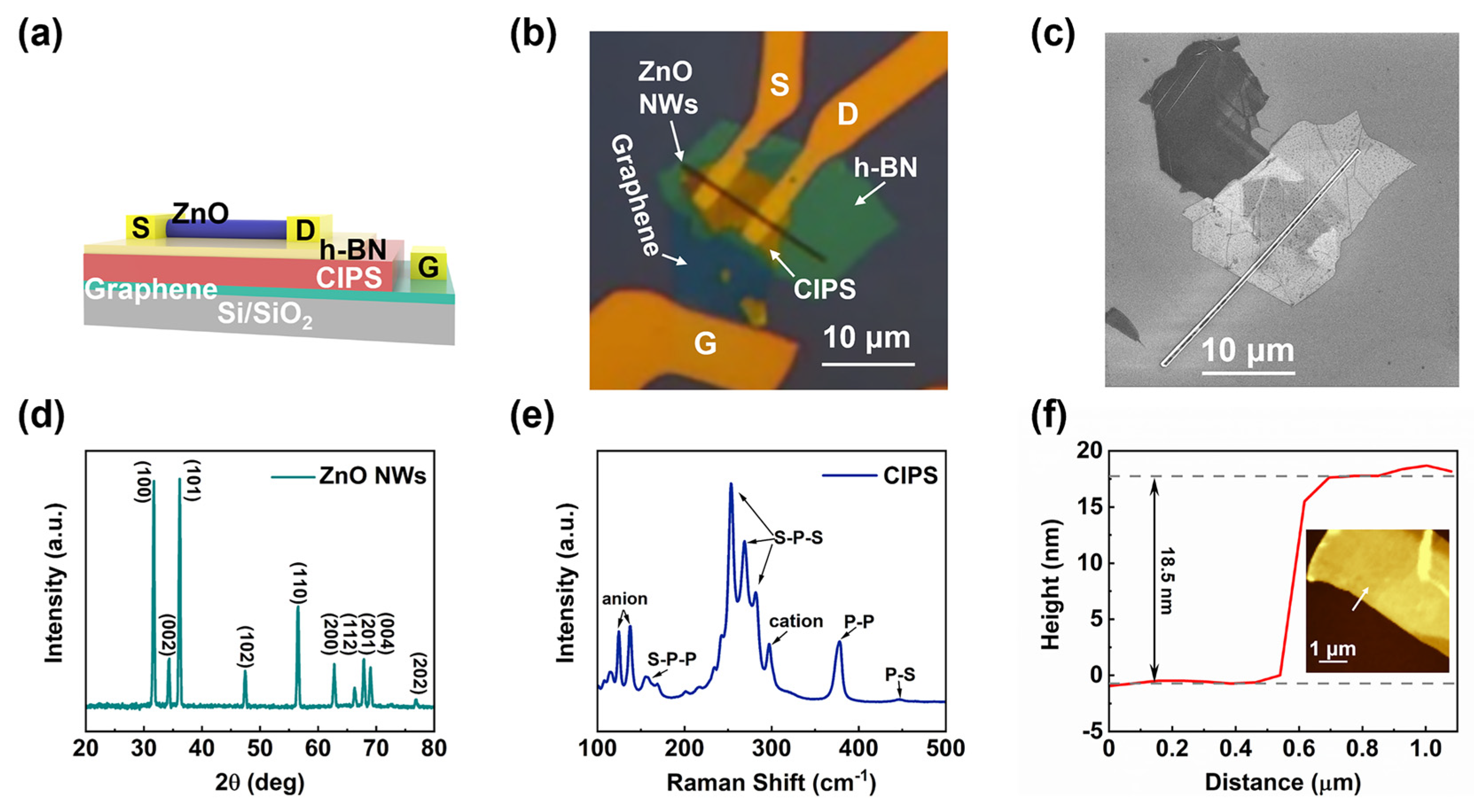
2.2. Preparation of ZnO NW Device
2.3. Preparation of ZnO Film Device
2.4. Characterizations
3. Results and Discussion
4. Conclusions
Supplementary Materials
Author Contributions
Funding
Acknowledgments
Conflicts of Interest
References
- Ji, C.; Dey, D.; Peng, Y.; Liu, X.; Li, L.; Luo, J. Ferroelectricity-Driven Self-Powered Ultraviolet Photodetection with Strong Polarization Sensitivity in a Two-Dimensional Halide Hybrid Perovskite. Angew. Chem. Int. Ed. 2020, 59, 18933–18937. [Google Scholar] [CrossRef] [PubMed]
- Zhao, M.; Hao, Y.; Zhang, C.; Zhai, R.; Liu, B.; Liu, W.; Wang, C.; Jafri, S.H.M.; Razaq, A.; Papadakis, R.; et al. Advances in Two-Dimensional Materials for Optoelectronics Applications. Crystals 2022, 12, 1087. [Google Scholar] [CrossRef]
- Benyahia, K.; Djeffal, F.; Ferhati, H.; Bendjerad, A.; Benhaya, A.; Saidi, A. Self-powered photodetector with improved and broadband multispectral photoresponsivity based on ZnO-ZnS composite. J. Alloys Compd. 2021, 859, 158242. [Google Scholar] [CrossRef]
- Yuan, J.; Hu, L.; Xu, Z.; Zhang, Y.; Li, H.; Cao, X.; Liang, H.; Ruan, S.; Zeng, Y.J. Concurrent Improvement of Photocarrier Separation and Extraction in ZnO Nanocrystal Ultraviolet Photodetectors. J. Phys. Chem. C 2019, 123, 14766–14773. [Google Scholar] [CrossRef]
- Jain, S.K.; Low, M.X.; Taylor, P.D.; Tawfik, S.A.; Spencer, M.J.S.; Kuriakose, S.; Arash, A.; Xu, C.; Sriram, S.; Gupta, G.; et al. 2D/3D Hybrid of MoS2/GaN for a High-Performance Broadband Photodetector. ACS Appl. Electron. Mater. 2021, 3, 2407–2414. [Google Scholar] [CrossRef]
- Zeng, Y.J.; Ye, Z.Z.; Xu, W.Z.; Li, D.Y.; Lu, J.G.; Zhu, L.P.; Zhao, B.H. Dopant source choice for formation of p-type ZnO: Li acceptor. Appl. Phys. Lett. 2006, 88, 062107. [Google Scholar] [CrossRef]
- Alwadai, N.; Mitra, S.; Hedhili, M.N.; Alamoudi, H.; Xin, B.; Alaal, N.; Roqan, I.S. Enhanced-Performance Self-Powered Solar-Blind UV-C Photodetector Based on n-ZnO Quantum Dots Functionalized by p-CuO Micro-pyramids. ACS Appl. Mater. Interfaces 2021, 13, 33335–33344. [Google Scholar] [CrossRef]
- Zhang, Y.; Zhao, X.; Chen, J.; Li, S.; Yang, W.; Fang, X. Self-Polarized BaTiO3 for Greatly Enhanced Performance of ZnO UV Photodetector by Regulating the Distribution of Electron Concentration. Adv. Funct. Mater. 2019, 30, 1907650. [Google Scholar] [CrossRef]
- Guo, Y.; Zhang, L.; Jin, D.; Lu, Y.; Xu, Z.; Jiang, J.; Yang, Z.; Liang, H.; Fang, H.; Ruan, S.; et al. 2D Allotrope of Carbon for Self-Powered, Flexible, and Transparent Optoelectronics. Adv. Opt. Mater. 2021, 9, 2001551. [Google Scholar] [CrossRef]
- Jiang, J.; Guo, Y.; Weng, X.; Long, F.; Xin, Y.; Lu, Y.; Ye, Z.; Ruan, S.; Zeng, Y.J. A tailorable polarity-flipping response in self-powered, flexible Sb2Se3/ZnO bilayer photodetectors. J. Mater. Chem. C 2021, 9, 4978–4988. [Google Scholar] [CrossRef]
- Dai, M.; Chen, H.; Wang, F.; Hu, Y.; Wei, S.; Zhang, J.; Wang, Z.; Zhai, T.; Hu, P.A. Robust Piezo-Phototronic Effect in Multilayer γ-InSe for High-Performance Self-Powered Flexible Photodetectors. ACS Nano 2019, 13, 7291–7299. [Google Scholar] [CrossRef] [PubMed]
- Xin, Y.; Jiang, J.; Lu, Y.; Liang, H.; Zeng, Y.J.; Ye, Z. Self-Powered Broad Spectral Photodetector with Ultrahigh Responsivity and Fast Response Based on Sb2Se3/VO2 Heterojunction. Adv. Mater. Interfaces 2021, 8, 2100058. [Google Scholar] [CrossRef]
- Jiang, J.; Wen, Y.; Wang, H.; Yin, L.; Cheng, R.; Liu, C.; Feng, L.; He, J. Recent Advances in 2D Materials for Photodetectors. Adv. Electron. Mater. 2021, 7, 2001125. [Google Scholar] [CrossRef]
- Lv, L.; Zhuge, F.; Xie, F.; Xiong, X.; Zhang, Q.; Zhang, N.; Huang, Y.; Zhai, T. Reconfigurable two-dimensional optoelectronic devices enabled by local ferroelectric polarization. Nat. Commun. 2019, 10, 3331. [Google Scholar] [CrossRef] [PubMed]
- Tian, H.; Wang, X.; Zhu, Y.; Liao, L.; Wang, X.; Wang, J.; Hu, W. High performance top-gated ferroelectric field effect transistors based on two-dimensional ZnO nanosheets. Appl. Phys. Lett. 2017, 110, 43505. [Google Scholar] [CrossRef]
- Wang, J.; Hu, W. Recent progress on integrating two-dimensional materials with ferroelectrics for memory devices and photodetectors. Chin. Phys. B 2017, 26, 114–120. [Google Scholar] [CrossRef]
- Wu, S.; Chen, Y.; Wang, X.; Jiao, H.; Zhao, Q.; Huang, X.; Tai, X.; Zhou, Y.; Chen, H.; Wang, X.; et al. Ultra-sensitive polarization-resolved black phosphorus homojunction photodetector defined by ferroelectric domains. Nat. Commun. 2022, 13, 3198. [Google Scholar] [CrossRef]
- Wang, X.; Wang, P.; Wang, J.; Hu, W.; Zhou, X.; Guo, N.; Huang, H.; Sun, S.; Shen, H.; Lin, T.; et al. Ultrasensitive and Broadband MoS2 Photodetector Driven by Ferroelectrics. Adv. Mater. 2015, 27, 6575–6581. [Google Scholar] [CrossRef]
- Wu, G.; Wang, X.; Wang, P.; Huang, H.; Chen, Y.; Sun, S.; Shen, H.; Lin, T.; Wang, J.; Zhang, S.; et al. Visible to short wavelength infrared In2Se3-nanoflake photodetector gated by a ferroelectric polymer. Nanotechnology 2016, 27, 364002. [Google Scholar] [CrossRef]
- Gao, J.; Lian, X.; Chen, Z.; Shi, S.; Li, E.; Wang, Y.; Jin, T.; Chen, H.; Liu, L.; Chen, J.; et al. Multifunctional MoTe2 Fe-FET Enabled by Ferroelectric Polarization-Assisted Charge Trapping. Adv. Funct. Mater. 2022, 32, 2110415. [Google Scholar] [CrossRef]
- Zhao, X.; Song, K.; Huang, H.; Han, W.; Yang, Y. Ferroelectric Materials for Solar Energy Scavenging and Photodetectors. Adv. Opt. Mater. 2022, 10, 2101741. [Google Scholar] [CrossRef]
- Biswas, P.P.; Pal, S.; Subramanian, V.; Murugavel, P. Polarization driven self-biased and enhanced UV-visible photodetector characteristics of ferroelectric thin film. J. Phys. D Appl. Phys. 2020, 53, 275302. [Google Scholar] [CrossRef]
- Wang, P.; Wang, Y.; Ye, L.; Wu, M.; Xie, R.; Wang, X.; Chen, X.; Fan, Z.; Wang, J.; Hu, W. Ferroelectric Localized Field-Enhanced ZnO Nanosheet Ultraviolet Photodetector with High Sensitivity and Low Dark Current. Small 2018, 14, 1800492. [Google Scholar] [CrossRef] [PubMed]
- Liu, L.; Wang, X.; Han, L.; Tian, B.; Chen, Y.; Wu, G.; Li, D.; Yan, M.; Wang, T.; Sun, S.; et al. Electrical characterization of MoS2 field-effect transistors with different dielectric polymer gate. AIP Adv. 2017, 7, 65121. [Google Scholar] [CrossRef]
- Qi, L.; Ruan, S.; Zeng, Y.J. Review on Recent Developments in 2D Ferroelectrics: Theories and Applications. Adv. Mater. 2021, 33, 2005098. [Google Scholar] [CrossRef] [PubMed]
- Wu, G.; Wang, X.; Chen, Y.; Wu, S.; Wu, B.; Jiang, Y.; Shen, H.; Lin, T.; Liu, Q.; Wang, X.; et al. MoTe2 p-n Homojunctions Defined by Ferroelectric Polarization. Adv. Mater. 2020, 32, 1907937. [Google Scholar] [CrossRef]
- Zhang, Y.; Jie, W.; Chen, P.; Liu, W.; Hao, J. Ferroelectric and Piezoelectric Effects on the Optical Process in Advanced Materials and Devices. Adv. Mater. 2018, 30, 1707007. [Google Scholar] [CrossRef]
- Zeng, Y.J.; Pereira, L.M.C.; Menghini, M.; Temst, K.; Vantomme, A.; Locquet, J.P.; Van Haesendonck, C. Tuning Quantum Corrections and Magnetoresistance in ZnO Nanowires by Ion Implantation. Nano Lett. 2012, 12, 666–672. [Google Scholar] [CrossRef]
- Jiang, J.; Huang, J.; Ye, Z.; Ruan, S.; Zeng, Y.J. Self-Powered and Broadband Photodetector Based on SnS2/ZnO1−xSx Heterojunction. Adv. Mater. Interfaces 2020, 7, 2000882. [Google Scholar] [CrossRef]
- Si, M.; Liao, P.; Qiu, G.; Duan, Y.; Ye, P.D. Ferroelectric Field-Effect Transistors Based on MoS2 and CuInP2S6 Two-Dimensional van der Waals Heterostructure. ACS Nano 2018, 12, 6700–6705. [Google Scholar] [CrossRef]
- Huang, W.; Wang, F.; Yin, L.; Cheng, R.; Wang, Z.; Sendeku, M.G.; Wang, J.; Li, N.; Yao, Y.; He, J. Gate-Coupling-Enabled Robust Hysteresis for Nonvolatile Memory and Programmable Rectifier in Van der Waals Ferroelectric Heterojunctions. Adv. Mater. 2020, 32, 1908040. [Google Scholar] [CrossRef] [PubMed]
- Arrigoni, A.; Brambilla, L.; Bertarelli, C.; Serra, G.; Tommasini, M.; Castiglioni, C. P(VDF-TrFE) nanofibers: Structure of the ferroelectric and paraelectric phases through IR and Raman spectroscopies. RSC Adv. 2020, 10, 37779–37796. [Google Scholar] [CrossRef] [PubMed]
- Huang, H.; Wang, X.; Wang, P.; Wu, G.; Chen, Y.; Meng, C.; Liao, L.; Wang, J.; Hu, W.; Shen, H.; et al. Ferroelectric polymer tuned two dimensional layered MoTe2 photodetector. RSC Adv. 2016, 6, 87416–87421. [Google Scholar] [CrossRef]
- Lv, T.; Li, J.; Arif, N.; Qi, L.; Lu, J.; Ye, Z.; Zeng, Y.J. Polarization and external-field enhanced photocatalysis. Matter 2022, 5, 2685–2721. [Google Scholar] [CrossRef]
- Gong, C.; Chu, J.; Yin, C.; Yan, C.; Hu, X.; Qian, S.; Hu, Y.; Hu, K.; Huang, J.; Wang, H.; et al. Self-Confined Growth of Ultrathin 2D Nonlayered Wide-Bandgap Semiconductor CuBr Flakes. Adv. Mater. 2019, 31, 1903580. [Google Scholar] [CrossRef]
- Gong, M.; Liu, Q.; Goul, R.; Ewing, D.; Casper, M.; Stramel, A.; Elliot, A.; Wu, J.Z. Printable Nanocomposite FeS2–PbS Nanocrystals/Graphene Heterojunction Photodetectors for Broadband Photodetection. ACS Appl. Mater. Interfaces 2017, 9, 27801. [Google Scholar] [CrossRef]
- Zheng, Z.; Zhuge, F.; Wang, Y.; Zhang, J.; Gan, L.; Zhou, X.; Li, H.; Zhai, T. Decorating Perovskite Quantum Dots in TiO2 Nanotubes Array for Broadband Response Photodetector. Adv. Funct. Mater. 2017, 27, 1703115. [Google Scholar] [CrossRef]
- Joshna, P.; Gollu, S.R.; Raj, P.M.P.; Rao, B.; Sahatiya, P.; Kundu, S. Plasmonic Ag nanoparticles arbitrated enhanced photodetection in p-NiO/n-rGO heterojunction for future self-powered UV photodetectors. Nanotechnology 2019, 30, 365201. [Google Scholar] [CrossRef]
- Xu, J.; Chen, J.; Cai, S.; Long, Z.; Zhang, Y.; Su, L.; He, S.; Tang, C.; Liu, P.; Peng, H.; et al. A Real-Time Wearable UV-Radiation Monitor based on a High-Performance p-CuZnS/n-TiO2 Photodetector. Adv. Mater. 2018, 30, 1803165. [Google Scholar] [CrossRef]


| Device | State | Dark Current (A) | Bias Voltage (V) | Responsivity (A/W) | Detectivity (Jones) | Rise/Decay Time (ms) |
|---|---|---|---|---|---|---|
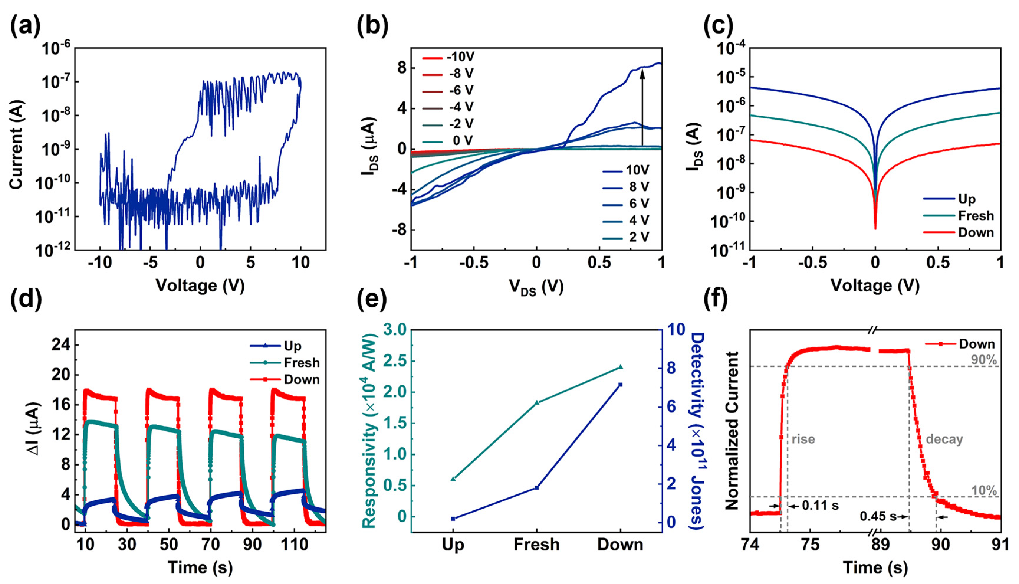
| ZnO NWs | Up | 4.19 × 10⁻⁷ | 0.1 | 0.60 × 10⁴ | 0.20 × 10¹¹ | 600/3780 |
| Fresh | 4.75 × 10⁻⁸ | 0.1 | 1.83 × 10⁴ | 1.81 × 10¹¹ | 420/5810 | |
| Down | 5.25 × 10⁻⁹ | 0.1 | 2.40 × 10⁴ | 7.17 × 10¹¹ | 110/450 | |
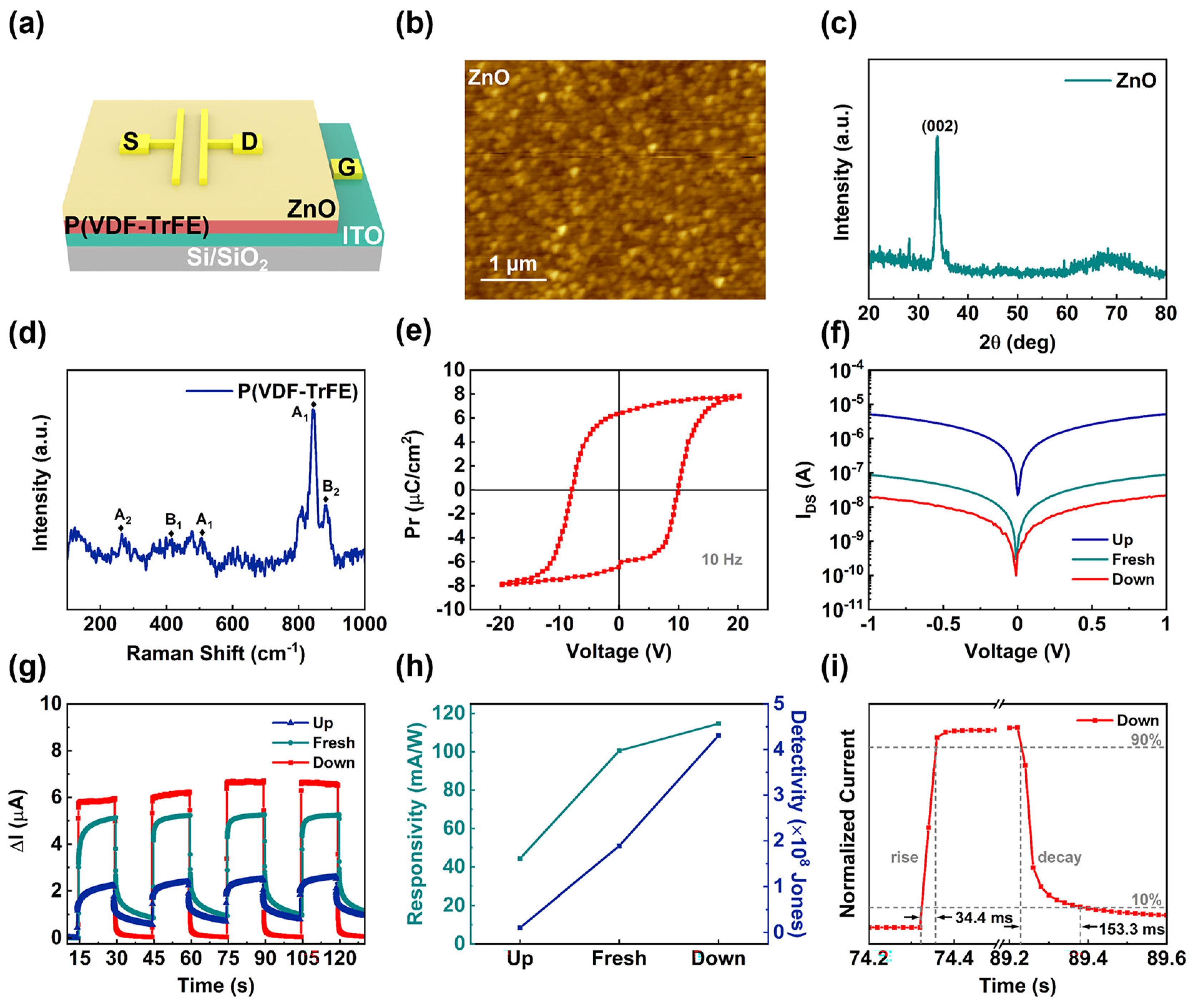
| ZnO film | Up | 5.24 × 10⁻⁶ | 1 | 0.044 | 1.08 × 10⁷ | 4570/10,590 |
| Fresh | 8.86 × 10⁻⁸ | 1 | 0.101 | 1.89 × 10⁸ | 715/5180 | |
| Down | 2.21 × 10⁻⁸ | 1 | 0.114 | 4.31 × 10⁸ | 34.4/153.3 |
Publisher’s Note: MDPI stays neutral with regard to jurisdictional claims in published maps and institutional affiliations. |
© 2022 by the authors. Licensee MDPI, Basel, Switzerland. This article is an open access article distributed under the terms and conditions of the Creative Commons Attribution (CC BY) license (https://creativecommons.org/licenses/by/4.0/).
Share and Cite
Xie, H.; Kang, C.; Iqbal, M.A.; Weng, X.; Wu, K.; Tang, W.; Qi, L.; Zeng, Y.-J. Ferroelectric Tuning of ZnO Ultraviolet Photodetectors. Nanomaterials 2022, 12, 3358. https://doi.org/10.3390/nano12193358
Xie H, Kang C, Iqbal MA, Weng X, Wu K, Tang W, Qi L, Zeng Y-J. Ferroelectric Tuning of ZnO Ultraviolet Photodetectors. Nanomaterials. 2022; 12(19):3358. https://doi.org/10.3390/nano12193358
Chicago/Turabian StyleXie, Haowei, Chenxu Kang, Muhammad Ahsan Iqbal, Xiaoliang Weng, Kewen Wu, Wei Tang, Lu Qi, and Yu-Jia Zeng. 2022. "Ferroelectric Tuning of ZnO Ultraviolet Photodetectors" Nanomaterials 12, no. 19: 3358. https://doi.org/10.3390/nano12193358
APA StyleXie, H., Kang, C., Iqbal, M. A., Weng, X., Wu, K., Tang, W., Qi, L., & Zeng, Y.-J. (2022). Ferroelectric Tuning of ZnO Ultraviolet Photodetectors. Nanomaterials, 12(19), 3358. https://doi.org/10.3390/nano12193358