
Combination of Micelle Collapse and CuNi Surface Dissolution for Electrodeposition of Magnetic Freestanding Chitosan Film


Abstract
:
1. Introduction
2. Materials and Methods
2.1. Reagents and Materials
2.2. Preparation of CuNi NPs
2.3. Electrodeposition of Chitosan
2.4. Characterization
3. Results
4. Conclusions
Author Contributions
Funding
Institutional Review Board Statement
Informed Consent Statement
Data Availability Statement
Acknowledgments
Conflicts of Interest
References
- Wang, Y.; Li, B.; Xu, F.; Han, Z.; Wei, D.; Jia, D.; Zhou, Y. Tough magnetic chitosan hydrogel nanocomposites for remotely stimulated drug release. Biomacromolecules 2018, 19, 3351–3360. [Google Scholar] [CrossRef]
- Park, N.; Kim, J. Hydrogel-based artificial muscle: Overview and recent progress. Adv. Intell. Syst. 2020, 2, 1900135. [Google Scholar] [CrossRef] [Green Version]
- Duan, J.; Liang, X.; Guo, J.; Zhu, K.; Zhang, L. Ultra-stretchable and force-sensitive hydrogels reinforced with chitosan microspheres embedded in polymer networks. Adv. Mater. 2016, 28, 8037–8044. [Google Scholar] [CrossRef]
- Jiang, D.; Huang, D.; Lai, C.; Xu, P.; Zeng, G.; Wan, J.; Tang, L.; Dong, H.; Huang, B.; Hu, T. Difunctional chitosan-stabilized Fe/Cu bimetallic nanoparticles for removal of hexavalent chromium wastewater. Sci. Total Environ. 2018, 644, 1181–1189. [Google Scholar] [CrossRef] [PubMed]
- Zhu, Y.; Hu, J.; Wang, J. Competitive adsorption of Pd (II), Cu (II) and Zn (II) onto xanthate-modified magnetic chitosan. J. Hazard. Mater. 2012, 221–222, 155–161. [Google Scholar] [CrossRef] [PubMed]
- Li, Y.; Liu, Y.; Gao, T.; Zhang, B.; Song, Y.; Terrell, J.L.; Barber, N.; Bentley, W.E.; Takeuchi, I.; Payne, G.F.; et al. Self-assembly with orthogonal-imposed stimuli to impart structure and confer magnetic function to electrodeposited hydrogels. ACS Appl. Mater. Interfaces 2015, 7, 10587–10598. [Google Scholar] [CrossRef]
- Ma, W.; Ya, F.; Han, M.; Wang, R. Characteristics of equilibrium, kinetics studies for adsorption of fluoride on magnetic-chitosan particles. J. Hazard. Mater. 2007, 143, 296–302. [Google Scholar] [CrossRef]
- Geng, Z.; Wang, X.; Guo, X.; Zhang, Z.; Chen, Y.; Wang, Y. Electrodeposition of chitosan based on coordination with metal ions in situ-generated by electrochemical oxidation. J. Mater. Chem. B 2016, 4, 3331–3338. [Google Scholar] [CrossRef]
- Milinkovic, J.; Petrovic, L.; Fraj, J.; Bucko, S.; Katona, J.; Spasojevic, L. Interfacial and emulsifying properties of chitosan/sodium lauryl ether sulfate system. Colloids Surf. 2018, 557, 9–13. [Google Scholar] [CrossRef]
- Fan, C.; Li, K.; He, Y.; Wang, Y.; Qian, X.; Jia, J. Evaluation of magnetic chitosan beads for adsorption of heavy metal ions. Sci. Total Environ. 2018, 627, 1396–1403. [Google Scholar] [CrossRef]
- Shaumbwa, V.R.; Liu, D.; Archer, B.; Li, J.; Su, F. Preparation and application of magnetic chitosan in environmental remediation and other fields: A review. J. Appl. Polym. Sci. 2021, 138, e51241. [Google Scholar] [CrossRef]
- Assa, F.; Jafarizadeh-Malmiri, H.; Ajamein, H.; Vaghari, H.; Anarjan, N.; Ahmadi, O.; Berenjian, A. Chitosan magnetic nanoparticles for drug delivery system. Crit. Rev. Biotechnol. 2017, 37, 492–509. [Google Scholar] [CrossRef] [PubMed]
- Li, X.; Zeng, D.; Ke, P.; Wang, G.; Zhang, D. Synthesis and characterization of magnetic chitosan microspheres for drug delievery. RSC Adv. 2020, 10, 7163–7169. [Google Scholar] [CrossRef] [PubMed] [Green Version]
- Li, X.; Zeng, D.; He, Z.; Ke, P.; Tian, Y.; Wang, G. Magnetic chitosan microspheres: An efficient and recyclable adsorbent for the removal of iodide from simulated nuclear wastewater. Carbohyd. Polym. 2022, 276, 118729. [Google Scholar] [CrossRef] [PubMed]
- Xu, P.; Liang, X.; Chen, N.; Tang, J.; Shao, W.; Gao, Q.; Teng, Z. Magnetic separable chitosan microcapsules decorated with silver nanoparticles for catalytic reduction of 4-nitrophenol. J. Colloid. Interface Sci. 2017, 507, 353–359. [Google Scholar] [CrossRef] [PubMed]
- Meyer, W.L.; Liu, Y.; Shi, X.W.; Yang, X.; Bentley, W.E.; Payne, G.F. Chitosan-coated wires: Conferring electrical properties to chitosan fibers. Biomacromolecules 2009, 10, 858–864. [Google Scholar] [CrossRef] [PubMed]
- Gray, K.M.; Liba, B.D.; Wang, Y.; Cheng, Y.; Rubloff, G.W.; Bentley, W.E.; Montembault, A.; Royaud, I.; David, L.; Payne, G.E. Electrodeposition of a biopolymeric hydrogel: Potential for one-step protein electroaddressing. Biomacromolecules 2012, 13, 1181–1189. [Google Scholar] [CrossRef]
- Karimzaeh, I.; Aghazadeh, M.; Doroudi, T.; Ganjali, M.R.; Kolivand, P.H. Electrochemical preparation and characterization of chitosan-coated superparamagnetic iron oxide (Fe3O4) nanoparticles. Mater. Res. Innov. 2018, 22, 352–360. [Google Scholar]
- Ahmad, R.; Mirza, A. Facile one pot green synthesis of chitosan-iron oxide (CS-Fe2O3) nanocomposite: Removal of Pd (II) and Cd (II) from synthetic and industrial wastewater. J. Clean. Prod. 2018, 186, 342–352. [Google Scholar] [CrossRef]
- Moghaddam, A.Z.; Ghiamati, E.; Pourashuri, A.; Allahresani, A. Modified nickel ferrite nanocomposite/functionalized chitosan as a novel adsorbent for the removal of acidic dyes. Int. J. Bio. Macromol. 2018, 120, 1714–1725. [Google Scholar] [CrossRef] [PubMed]
- Chew, S.Y.; Ng, S.H.; Wang, J.; Novak, P.; Krumeich, F.; Chou, S.L.; Chen, J.; Liu, H.K. Flexible free-standing carbon nanotube films for model lithium-ion batteries. Carbon 2009, 47, 2976–2983. [Google Scholar] [CrossRef]
- He, Y.; Chen, W.; Li, X.; Zhang, Z.; Fu, J.; Zhao, C.; Xie, E. Freestanding three-dimensional graphene/MnO2 composite networks as ultralight and flexible supercapacitor electrodes. ACS Nano 2013, 7, 174–182. [Google Scholar] [CrossRef] [PubMed]
- Wang, Y.; Wang, X.; Ge, B.; Guo, J.; Fernandez, C.; Peng, Q. Freestanding MXene-MnO2 films for Li-CO2 cathodes with low overpotential and long-term cycling. ACS Appl. Mater. Interfaces 2021, 4, 9961–9968. [Google Scholar] [CrossRef]
- Cui, G.; Peng, Z.; Chen, X.; Cheng, Y.; Lu, L.; Cao, S.; Ji, S.; Qu, G.; Zhao, L.; Wang, S.; et al. Freestanding graphene fabric film for flexible infrared camouflage. Adv. Sci. 2022, 9, 2105004. [Google Scholar] [CrossRef] [PubMed]
- Moura, D.; Caridade, S.G.; Sousa, M.P.; Cunha, E.; Rocha, H.C.; Mano, J.F.; Paiva, M.C.; Alves, N.M. High performance freestanding films by layer-by-layer assembly of graphene flakes and ribbons with natural polymer. J. Mater. Chem. B 2016, 4, 7718–7730. [Google Scholar] [CrossRef] [PubMed] [Green Version]
- Jo, Y.K.; Kim, I.Y.; Kim, S.J.; Shin, S.I.; Go, A.; Lee, Y.; Hwang, S.J. Non-monotonous dependence of the electrical conductivity and chemical stability of a graphene freestanding film on the degree of reduction. RSC Adv. 2015, 5, 19259–19263. [Google Scholar] [CrossRef]
- Zhang, J.; Baro, M.D.; Pellicer, E.; Sort, J. Electrodeposition of magnetic, superhydrophobic, non-stick, two-phase Cu–Ni foam films and their enhanced performance for hydrogen evolution reaction in alkaline water media. Nanoscale 2014, 6, 12490–12499. [Google Scholar] [CrossRef]
- Zhang, J.; Quintana, A.; Menendez, E.; Coll, M.; Pellicer, E.; Sort, J. Electrodeposited Ni-based magnetic mesoporous films as smart surfaces for atomic layer deposition: An “all-chemical” deposition approach toward 3D nanoengineered composite layers. ACS Appl. Mater. Interfaces 2018, 10, 14877–14885. [Google Scholar] [CrossRef] [Green Version]
- Pellicer, E.; Varea, A.; Pane, S.; Nelson, B.J.; Menendez, E.; Estrader, M.; Surinach, S.; Baro, M.D.; Nogues, J.; Sort, J. Nanocrystalline electroplated Cu–Ni: Metallic thin films with enhanced mechanical properties and tunable magnetic behavior. Adv. Funct. Mater. 2010, 20, 983–991. [Google Scholar] [CrossRef]
- Bai, J.; Wang, X.; Zhang, M.; Zhang, J.; Chen, X.; An, Y.; Guan, R. A CuNi-loaded porous magnetic soft materials: Preparation, characterization and magnetic field-controlled modulus. Materials 2022, 15, 1412. [Google Scholar] [CrossRef] [PubMed]
- Kraemer, E.O.; Dexter, S.T. The light-scattering capacity (Tyndall effect) and colloidal behavior of gelatin sols and gels. J. Phys. Chem. 1927, 31, 764–782. [Google Scholar] [CrossRef]
- Liu, Y.; Peng, N.; Yao, Y.; Zhang, X.; Peng, X.; Zhao, L.; Wang, J.; Peng, L.; Wang, Z.; Mochizuki, K.; et al. Breaking the nanoparticle’s dispersible limit viarotatable surface ligands. Nat. Commun. 2022, 13, 3581. [Google Scholar] [CrossRef]
- Sun, L.; Hong, W.; Liu, J.; Yang, M.; Lin, W.; Chen, G.; Yu, D.; Chen, X. Cross-Linked Graphitic Carbon Nitride with Photonic CrystalStructure for Efficient Visible-Light-Driven Photocatalysis. ACS Appl. Mater. Interfaces 2017, 9, 44503–44511. [Google Scholar] [CrossRef] [PubMed]
- Liu, L.; Wan, Q.; Xu, X.; Duan, S.; Yang, C. Combination of micelle collapse and field-amplified sample stacking in capillary electrophoresis for determination of trimethoprim and sulfamethoxazole in animal-originated foodstuffs. Food Chem. 2017, 219, 7–12. [Google Scholar] [CrossRef] [PubMed]
- Amamou, A.; Gautier, F.; Loegel, B. Transport properties, giant moments and nearly magnetic impurities in some nickel alloys near the magnetic transition. J. Phys. F Met. Phys. 1974, 35, C4. [Google Scholar] [CrossRef] [Green Version]
- Fesharaki, M.J.; Péter, L.; Schucknecht, T.; Rafaja, D.; Dégi, J.; Pogány, L.; Neuróhr, K.; Széles, E.; Nabiyouni, G.; Bajonyi, I. Magnetoresistance and structural study of electrodeposited Ni-Cu/Cu multilayers. J. Electrochem. Soc. 2012, 159, D162–D171. [Google Scholar] [CrossRef] [Green Version]
- Ramesh, R.; Thomas, G.; Ma, B.M. Magnetization reversal in nucleation controlled magnets. II. Effect of grain size and size distribution on intrinsic coercivity of Fe-Nd-B magnets. J. Appl. Phys. 1988, 64, 6416–6423. [Google Scholar] [CrossRef]
- Hadjipanayis, G.C. Nanophase hard magnets. J. Magn. Magn. Mater. 1999, 200, 373–391. [Google Scholar] [CrossRef]


| Electrolyte | Electrode | Results | |||||
|---|---|---|---|---|---|---|---|
| Chitosan | NaCl | SDS | CuNi NPs | Graphite Power | Anode | Cathode | |
| √ | √ | √ | √ | Cu | Cu | +, − | |
| √ | √ | √ | Cu | Cu | × | ||
| √ | √ | √ | Cu | Cu | + | ||
| √ | √ | √ | √ | Cu | Cu | + | |
| √ | √ | √ | √ | Pt | Pt | +, − | |
| Ni-Rich Phase | Cu-Rich Phase | |
|---|---|---|
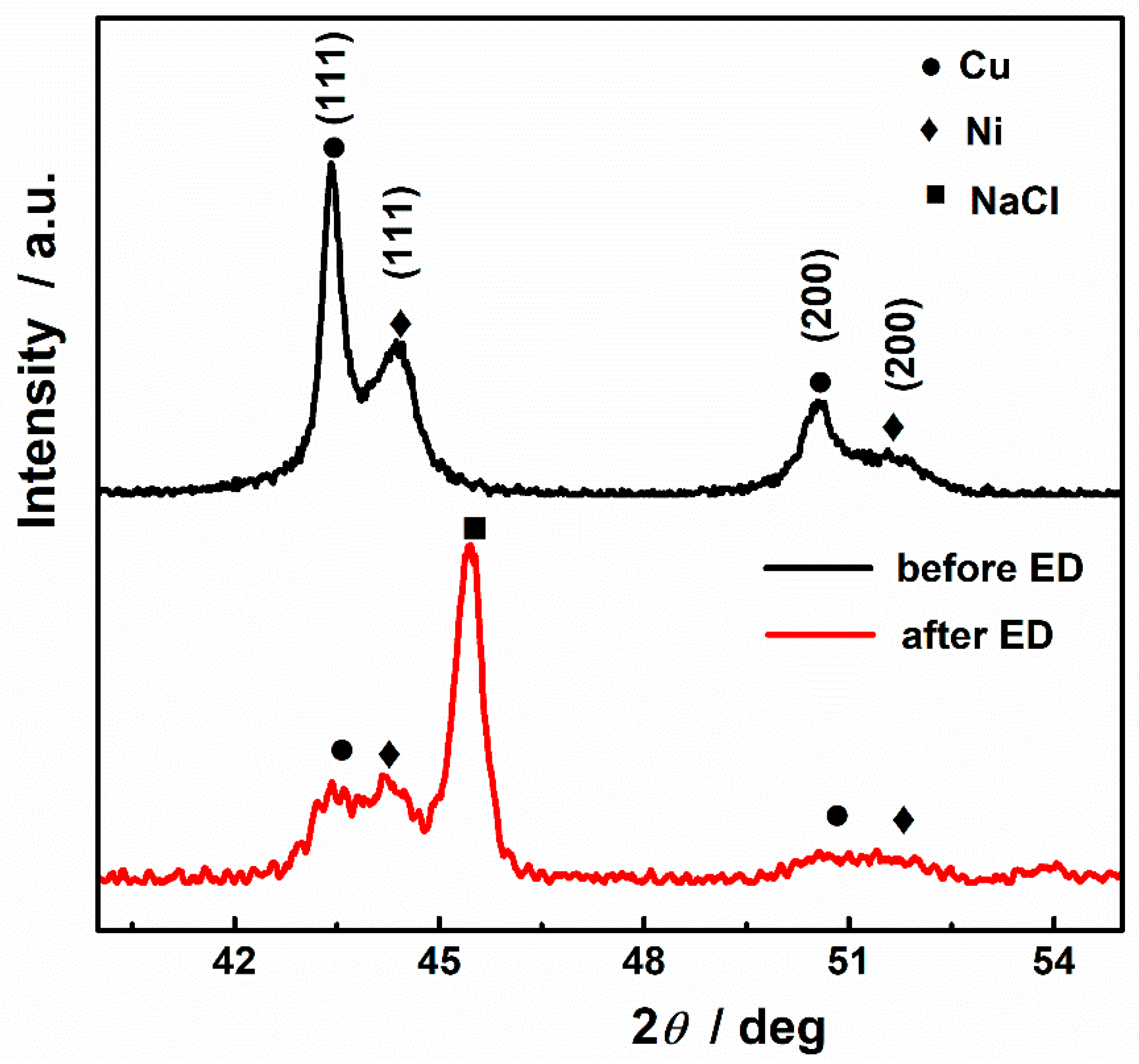
| CuNi NPs | 2θ = 44.46 (deg) | 2θ = 43.47 (deg) |
| d = 2.036 | d = 2.080 | |
| a = b = c = 3.527 Å | a = b = c = 3.603 Å | |
| at% Ni = 99.24% | at% Cu = 94.27% | |
| at% Cu = 0.76% | at% Ni = 5.73% | |
| Chitosan freestanding film | 2θ = 43.58 (deg) | 2θ = 42.60 (deg) |
| d = 2.075 | d = 2.120 | |
| a = b = c = 3.595 Å | a = b = c = 3.671 Å | |
| at% Ni = 95.88% | at% Cu = 94.47% | |
| at% Cu = 4.12% | at% Ni = 5.53% |
Publisher’s Note: MDPI stays neutral with regard to jurisdictional claims in published maps and institutional affiliations. |
© 2022 by the authors. Licensee MDPI, Basel, Switzerland. This article is an open access article distributed under the terms and conditions of the Creative Commons Attribution (CC BY) license (https://creativecommons.org/licenses/by/4.0/).
Share and Cite
Bai, J.; Zhang, M.; Wang, X.; Zhang, J.; Yang, Z.; Fan, L.; An, Y.; Guan, R. Combination of Micelle Collapse and CuNi Surface Dissolution for Electrodeposition of Magnetic Freestanding Chitosan Film. Nanomaterials 2022, 12, 2629. https://doi.org/10.3390/nano12152629
Bai J, Zhang M, Wang X, Zhang J, Yang Z, Fan L, An Y, Guan R. Combination of Micelle Collapse and CuNi Surface Dissolution for Electrodeposition of Magnetic Freestanding Chitosan Film. Nanomaterials. 2022; 12(15):2629. https://doi.org/10.3390/nano12152629
Chicago/Turabian StyleBai, Jingyuan, Meilin Zhang, Xuejiao Wang, Jin Zhang, Zhou Yang, Longyi Fan, Yanan An, and Renguo Guan. 2022. "Combination of Micelle Collapse and CuNi Surface Dissolution for Electrodeposition of Magnetic Freestanding Chitosan Film" Nanomaterials 12, no. 15: 2629. https://doi.org/10.3390/nano12152629
APA StyleBai, J., Zhang, M., Wang, X., Zhang, J., Yang, Z., Fan, L., An, Y., & Guan, R. (2022). Combination of Micelle Collapse and CuNi Surface Dissolution for Electrodeposition of Magnetic Freestanding Chitosan Film. Nanomaterials, 12(15), 2629. https://doi.org/10.3390/nano12152629