
Simple Synthesis and Characterization of Shell-Thickness-Controlled Ni/Ni3C Core-Shell Nanoparticles


The School of Advanced Materials Science and Engineering, SungKyunKwan University, Seobu-ro, Jangan-gu, Suwon-si 2066, Gyeonggi-do, Korea
*
Author to whom correspondence should be addressed.
Nanomaterials 2022, 12(12), 1954; https://doi.org/10.3390/nano12121954
Submission received: 10 May 2022
/
Revised: 27 May 2022
/
Accepted: 1 June 2022
/
Published: 7 June 2022
(This article belongs to the Topic Synthesis and Applications of Nanostructured Metals and Metal Oxides)
Abstract
:Ni/Ni3C core-shell nanoparticles with an average diameter of approximately 120 nm were carburized via a chemical solution method using triethylene glycol. It was found that over time, the nanoparticles were covered with a thin Ni3C shell measuring approximately 1–4 nm, and each Ni core was composed of poly grains. The saturation magnetization of the core-shell nanopowders decreased in proportion to the amount of Ni3C. The synthesis mechanism of the Ni/Ni3C core-shell nanoparticles was proposed through X-ray diffraction (XRD), X-ray photoelectron spectroscopy (XPS) and transmission electron microscopy (TEM) analyses.
1. Introduction
Nanosized magnetic materials of Fe, Co, and Ni have received much attention owing to their unique magnetic, catalytic, and optical properties, as well as their promising applications in magnetic sensors, high-density magnetic recording, catalysis, and biomedicine [1,2,3,4,5,6,7]. Nickel carbide (Ni3C) has received increasing attention because of its remarkable chemical stability, catalytic properties, and magnetic properties. Nanocomposite magnetic materials with a combination of two nanoscale phases have attracted significant attention because of their ability to generate magnetic properties that are not achievable by a single material [8,9]. Typically, Ni3C does not exist in nature owing to its instability. It is mainly obtained by physical methods under a high temperature and pressure, such as C-ion implantation into Ni, mechanical alloying, and the reaction of Ni with an amorphous C film [10,11,12,13,14]. Recently, a mild chemical solution method was employed in the synthesis of nanosized Ni3C. Most core-shell Ni-based nanomaterials have been reported to be Ni/C or Ni3C/C nanoparticles [15,16,17,18,19]. In previous studies, the synthesis was performed by the chemical solution method, and the shell structure of Ni3C was obtained at a low temperature. Although this experiment was also a chemical method, a shell structure of nickel carbide was obtained at a relatively low temperature. Ni/Ni3C core-shell nanoparticles (NICs) were synthesized at a lower temperature (523 K) by a simple two-step chemical solution method involving the synthesis of Ni nanoparticles (Ni Nps) and carburization, following which the structure, morphology, and related magnetic properties of the nanomaterials were studied. The structure, shape, and related magnetic properties of the nanomaterials were analyzed using the synthesized materials, and their growth mechanisms were studied. In addition, because of the non-ferromagnetism of Ni3C and ferromagnetism of Ni, the effect of carburization on the magnetic properties of Ni was investigated.
2. Materials and Methods
2.1. Synthesis of Ni Nps
(1) 0.5 g of a nickel chloride hexahydrate (NiCl2. 6H2O, 98%, Daejung, Siheung, Korea) precursor was dissolved in 60 mL of deionized water. (2) 1 g of sodium hydroxide (NaOH, 97%, Junsei, Tokyo, Japan) was added to 20 mL of deionized water. (3) 20 mL of hydrazine monohydrate (H4N2·H2O, 99%, Daejung, Siheung, Korea) was prepared as a reducing agent. After mixing them all, the solution with a light green color (arising from the Ni ions) turned blue. After heating the solution to 60 °C, ultrasonic treatment for 25 min resulted in the formation of black Ni Nps. These Nps were collected and washed several times with acetone and deionized water. After washing, the samples were stored in acetone.
2.2. Carburization to Obtain Ni/Ni3C Core-Shell Nanoparticles (NICs)
The prepared Ni Nps were transferred to a triethylene glycol (TEG, C6H14O4, 97%, Daejung, Siheung, Korea) solution that contained a small amount of NaOH. NICs were obtained by heating the solution to 250 °C at a heating rate of 8 °C/min for 15, 30, 45, and 60 min (resulting samples denoted as NIC15, NIC30, NIC45, and NIC60, respectively) at a rotational speed of 250 rpm.
2.3. Analysis of Samples
The phase compositions of the Ni Nps and NICs were identified by X-ray diffraction (XRD; D8 Advance HP, Bruker, Billerica, MA, USA) with Cu Kα radiation at 40 kV and 150 mA. The patterns were recorded over an angular range of 10–90° (2θ) at a scan rate of 5 °/min. The shape, size, and crystallinity of the samples were analyzed using scanning electron microscopy (SEM; XL30 FEG, Philips, Amsterdam, Netherlands) and high-resolution transmission electron microscopy (HRTEM; JEM F 200, JEOL, Tokyo, Japan). Binding energy observations to confirm the increase in the C content were performed using X-ray photoelectron spectroscopy (XPS ESCA2000, VG Microtech, London, UK). The magnetic properties of the prepared samples were measured using a vibrating sample magnetometer (VSM; DMS1660, Microsense, Lowell, MA, USA).
3. Results and Discussion
Figure 1 shows the SEM images of the Ni Nps and NICs. Figure 1a,b show images at different magnifications, indicating that the Ni Nps are formed in a slightly distorted spherical shape. In Figure 1c–f, for each synthesis time, the NICs do not appear to differ significantly from the Ni Nps. As summarized in Figure 1g, the average size of the Ni Nps is 122.64 nm and those of the NICs are 120.33, 123.08, 122.67, and 124.29 nm, with respect to the processing time. It was difficult to observe changes in the shape or size of the NICs due to the reaction and temperature during carburization.
Figure 2a–d show the EDS data of the NICs synthesized by carburization according to the process time (15, 30, 45, and 60 min). With an increasing processing time of the NICs, the atomic percentage of Ni gradually decreases, but those of C increase to 5.7, 9.88, 11.5, and 16.03%. Thus, it was determined that C was gradually added to the Ni Nps according to the processing time.
Figure 3a shows the XRD patterns of the Ni Nps and NICs prepared at various processing times. All samples exhibit a single phase without impurities. The Ni Nps exhibit peaks at 2θ values of 44.48, 51.83, and 76.35°, corresponding to the (111), (200), and (220) crystal planes of Ni (JCPDS card number 70-1849). As the carburization time increases, the peak corresponding to Ni decreases and gradually peaks at positions 39.27, 41.75, 44.52, 58.62, 71.20, and 78.10°, corresponding to the (110), (006), (113), (116), (300), and (119) planes and indexed with Ni3C (JCPDS card number 06-0697) [19]. Figure 3b is an enlarged graph of the Ni(111) and Ni3C(113) peaks, which are the major diffraction peaks of Ni and Ni3C. A peak shift occurs as the processing time increases. This is because the C atom occupies an interstitial position, resulting in a shift of the peak toward a higher angle [20,21,22].
Figure 4 is a time-dependent TEM image of the sample before and after carburization. In Figure 4a–e, the same coarse spherical particles as observed in the SEM images are noticeable. In Figure 4f–j, which are the high-magnification bright-field TEM images, the Ni3C shell layer on the particle surface gradually increases in size to 0.91, 1.41, 2.00, and 2.90 nm with an increasing treatment time. In other words, this result shows that the thickness of the Ni3C shell on the Ni core can be tuned with the processing time.
Figure 5 shows the EDS elemental maps of the Ni Nps and NIC60 captured from the enclosed regions in the TEM images for Ni and C. In Figure 5a, there is no C element around Ni except for the C-supported TEM grid. However, in Figure 5b, a large amount of C is present in the Ni shell. This confirms that C is carburized on the surface of Ni through the employed process. The fast Fourier transform (FFT) pattern of the Ni Nps is shown in Figure 5c. The diffraction pattern of the Ni Nps is ring-like and shows polycrystalline characteristics. The indicated diffraction spots in the FFT pattern correspond to each grating region. From the inverse calculation of the D spacing through the location of the spot with a high intensity, the plane spacings are 0.204 and 0.177 nm. This implies that 0.204 nm and 0.177 nm are the D-spacings in the (111) and (200) plane directions of Ni, respectively. Hence, the Ni Nps appear to be pure Ni polycrystals. The fast Fourier transform (FFT) pattern of NIC60 is also shown in Figure 5d. The diffraction pattern in the proximity of the NIC60 shell shows ring-like polycrystalline characteristics. From the inverse calculation of the D spacing through the location of the spot with a high intensity, the plane spacings are determined to be 0.214, 0.157, and 0.177 nm. Here, 0.214 and 0.157 nm are the D spacings in the (006) and (116) plane directions of Ni3C, respectively, and 0.177 nm is the D spacing in the (200) plane direction of Ni. This confirms that NIC60 has a nickel–nickel carbide core-shell structure.
The XPS C1s spectra (Figure 6a–e) were measured to study the elemental composition and bonding states, and to confirm that carbon did not exist separately on the surface but reacted with Ni. A broad peak was observed in the C1s range of 281.0–290.0 eV, and five distinct binding energy (BE) peaks were obtained by deconvolution, assignable to five C species. The observed C1s peak at 284.7 eV is consistent with the C1s peak of the C-C bond. The C1s peak BEs of 286.1, 287.2, and 288.7 eV correspond to the C-O, C=O, and O-C=O bonds, respectively [23,24]. Unlike the Ni Nps, the NICs subjected to carburization exhibit a BE of 283.5 eV [25,26]. This can be attributed to the C1 of the Ni-C bond. The peak for the BE of 283.5 eV tends to increase with the processing time, which implies that more reactions occur and more C enters the Ni Nps.
The oxidation state of nickel in the surface region can be determined from the BE and chemical shift in the XPS Ni 2P2/3 spectrum (Figure 6f–j). Since nickel naturally oxidizes, such oxidation-related peaks appear for Ni Nps. The results of previous studies support the assignment of BEs of 852.6, 855–856, and 857–858 eV in the Ni 2P3/2 XPS spectra for Ni0, Ni2+, and Ni3+ in oxidized Ni, oxides, and hydroxides and oxyhydroxides, respectively [27,28,29]. The BE of 860.2 eV is characteristic of related satellite peaks. The slightly lower BE of 854.5 eV is assigned to partially reduced nickel species with a positive charge δ+ (Niδ+), indicative of the presence of a nickel carbide phase [30,31,32,33]. As the synthesis time increases, the ratio of this peak to the 2+ peak gradually increases, indicating that the ratio of nickel carbide in the powder increases.
The formation of the Ni/Ni3C core-shell structure can be described using the following simplified mechanism: TEG molecules derived from electrostatic interactions are adsorbed onto the polycrystalline Ni Nps surface. Activated C and CO are formed by the thermal decomposition of ethylene glycol [34] on the surface of the Ni particles. Subsequently, the activated C atoms and CO gradually diffuse from the surface to the Ni Nps by the C concentration gradient to form Ni3C compounds through the highly reactive polycrystalline grain boundaries and the catalytic activity of the Ni particles themselves [14]. Thus, an intact Ni core is formed in the center, and a core-shell structure is finally achieved. In summary, through the mechanism shown in Figure 7, it is inferred that carbon is activated through the thermal decomposition of TEG at a low temperature (less than 523 K) and the diffusion of Ni3C due to the catalytic role of polycrystalline Ni Nps that contribute to the formation of NICs. This is similar to the results of previous studies on cobalt carbide [35].
Figure 8 shows the magnetic hysteresis loops (M−H curves) at room temperature for the Ni Nps and NICs. A hysteresis loop was recorded after applying a magnetic field of up to 10,000 Oe. The saturation magnetization (Ms) of bulk Ni is 55.4 emu/g, and that of the Ni Nps is reduced to 46.2 emu/g. The number of spins on the surface increases as the particle size decreases; thus, the spin canting effect increases. Therefore, the Ms of the nanoparticles is lower than that of the bulk [36,37,38]. As shown, the Ms values of the samples obtained at 15, 30, 45, and 60 min of carburization are 41.6, 38.8, 37.4, and 35.8 emu/g, respectively. As the ratio of Ni3C in NICs increases, Ms decreases. Ni is a well-known ferromagnetic element, while Ni3C is known to be non-ferromagnetic. The gradual decrease in Ms can be explained by the magnetization reversal due to two causes: (1) The amount of Ni inside the particles is consumed due to the formation of the shell, and (2) the magnetic field transmission is disturbed due to the presence of the non-ferromagnetic shell [39,40].
4. Conclusions
In summary, NICs were formed by the surface modification of TEG at low temperatures (below 573 K). The Ni3C layer was formed by the diffusion of activated C atoms into the Ni particles on the surface. Nanoparticles with an average size of 120 nm and various ratios of Ni3C in NICs were produced by controlling the carburization process time. As the processing time increased, in the XRD pattern, the diffraction peak of Ni disappeared, and the diffraction peak of Ni3C appeared, indicating that Ni was transformed into Ni3C. The TEM analysis confirmed that the produced Ni particles were polycrystalline, and the Ni3C shell gradually thickened with the processing time. The change in the peak observed by XPS analysis was consistent with the XRD and TEM results, confirming that the Ni3C content of the reactant increased with the processing time. Thus, the growth mechanism could be elucidated. This proposed mechanism can guide the synthesis of similar core-shell nanomaterials. The magnetic properties of Ni can be controlled through the structure of the magnetic Ni core and non-magnetic Ni3C shell, and the oxidation resistance is expected to improve. This structure is expected to aid in the study of magnetization reversal mechanisms.
Author Contributions
Conceptualization, S.-W.K.; methodology, S.-W.K.; formal analysis, S.-W.K.; investigation, S.-W.K. and J.C.R.; resources, S.-W.K.; writing—original draft preparation, S.-W.K. and S.-J.S.; writing—review and editing, S.-W.K. and S.-J.S.; visualization S.-W.K.; supervision, J.C.R. and S.-J.S.; project administration, S.-J.S.; funding acquisition, S.-J.S. All authors have read and agreed to the published version of the manuscript.
Funding
This work was supported by the Korea Basic Science Institute (KBSI) National Research Facilities and Equipment Center (NFEC) grant funded by the Korea government (Ministry of Education) (No. 2019R1A6C1010031) and the Korea Evaluation Institute of Industrial Technology (KEIT) grant funded by the Ministry of Trade, Industry and Energy (No. 1415177850).
Institutional Review Board Statement
Not applicable.
Informed Consent Statement
Not applicable.
Data Availability Statement
Not applicable.
Conflicts of Interest
The authors declare no conflict of interest.
References
- Lenz, J.; Edelstein, S. Magnetic Sensors and Their Applications. IEEE Sens. J. 2006, 6, 631–649. [Google Scholar] [CrossRef]
- Khan, M.A.; Sun, J.; Li, B.; Przybysz, A.; Kosel, J. Magnetic Sensors-A Review and Recent Technologies. Eng. Res. Express 2021, 3, 022005. [Google Scholar] [CrossRef]
- Fan, H.; Xie, H.; Mao, J.; Liu, J.M.; Diao, X.; Wei, Q.; Feng, Q. Modelling of Using Hall Magnetic Sensor for Environmental Monitor of Micrometer-Sized Magnetite Particles. In Proceedings of the 15th Annual IEEE International Systems Conference (SysCon), Vancouver, BC, Canada, 15 April–15 May 2021; pp. 4–7. [Google Scholar] [CrossRef]
- Karimzadeh, A.; Aliofkhazraei, M.; Walsh, F.C. A Review of Electrodeposited Ni-Co Alloy and Composite Coatings: Microstructure, Properties and Applications. Surf. Coatings Technol. 2019, 372, 463–498. [Google Scholar] [CrossRef]
- Tolani, S.C.; Golhar, A.R.; Rewatkar, K.G. A Review of Morphological, Structural Behaviour and Technological Applications of Ferrites. In AIP Conference Proceedings; AIP Publishing LLC: Melville, NY, USA, 2019; Volume 2104, p. 030032. [Google Scholar] [CrossRef]
- Radhika, M.G.; Gopalakrishna, B.; Chaitra, K.; Bhatta, L.K.G.; Venkatesh, K.; Sudha Kamath, M.K.; Kathyayini, N. Electrochemical Studies on Ni, Co & Ni/Co-MOFs for High-Performance Hybrid Supercapacitors. Mater. Res. Express 2020, 7, 054003. [Google Scholar] [CrossRef]
- Zhu, J.; Zhao, Y.; Zulfiqar, M.; Zeng, S.; Ni, J. Electronic and Magnetic Properties of Fe-, Co-, and Ni-Decorated BC 3: A First-Principles Study. Phys. Lett. A 2018, 382, 1395–1400. [Google Scholar] [CrossRef]
- Kneller, E.F.; Hawig, R. The Exchange-Spring Magnet: A New Material Principle for Permanent Magnets. IEEE Trans. Magn. 1991, 27, 3588–3600. [Google Scholar] [CrossRef]
- Callen, E.; Liu, Y.J.; Cullen, J.R. Initial Magnetization, Remanence, and Coercivity of the Random Anisotropy Amorphous Ferromagnet. Phys. Rev. B 1977, 16, 263–270. [Google Scholar] [CrossRef]
- Nagakura, S. Study of Metallic Carbides by Electron Diffraction Part I. Formation and Decomposition of Nickel Carbide. J. Phys. Soc. Jpn. 1957, 12, 482–494. [Google Scholar] [CrossRef]
- Yue, L.; Sabiryanov, R.; Kirkpatrick, E.M.; Leslie-Pelecky, D.L. Magnetic Properties of Disordered Ni3C. Phys. Rev. B 2000, 62, 8969–8975. [Google Scholar] [CrossRef] [Green Version]
- Tokumitsu, K. Synthesis of Metastable Fe3C, Co3C and Ni3C by Mechanical Alloying Method. Mater. Sci. Forum 1996, 235–238, 127–132. [Google Scholar] [CrossRef]
- Wang, J.; Wu, X.F.; Liu, B.X.; Fang, Z.Z. Correlation of 3d Transition Metal Carbide Phase Formation with 3d Electrons by Carbon Ion Implantation. Acta Metall. Mater. 1992, 40, 1417–1420. [Google Scholar] [CrossRef]
- Sinharoy, S.; Smith, M.A.; Levenson, L.L. Thermal Decomposition of Nickel Carbide Thin Films. Surf. Sci. 1978, 72, 710–718. [Google Scholar] [CrossRef]
- Zhu, G.X.; Wei, X.W.; Jiang, S. A Facile Route to Carbon-Coated Nickel-Based Metal Nanoparticles. J. Mater. Chem. 2007, 17, 2301–2306. [Google Scholar] [CrossRef]
- Sun, X.C.; Dong, X.L. Magnetic Properties and Microstructure of Carbon Encapsulated Ni Nanoparticles and Pure Ni Nanoparticles Coated with NiO Layer. Mater. Res. Bull. 2002, 37, 991–1004. [Google Scholar] [CrossRef]
- Sun, X.; Gutierrez, A.; Yacaman, M.J.; Dong, X.; Jin, S. Investigations on Magnetic Properties and Structure for Carbon Encapsulated Nanoparticles of Fe, Co, Ni. Mater. Sci. Eng. A 2000, 286, 157–160. [Google Scholar] [CrossRef]
- Nishijo, J.; Okabe, C.; Oishi, O.; Nishi, N. Synthesis, Structures and Magnetic Properties of Carbon-Encapsulated Nanoparticles via Thermal Decomposition of Metal Acetylide. Carbon N. Y. 2006, 44, 2943–2949. [Google Scholar] [CrossRef]
- Zhou, W.; Zheng, K.; He, L.; Wang, R.; Guo, L.; Chen, C.; Han, X.; Zhang, Z. Ni/Ni3C Core-Shell Nanochains and Its Magnetic Properties: One-Step Synthesis at Low Temperature. Nano Lett. 2008, 8, 1147–1152. [Google Scholar] [CrossRef] [PubMed] [Green Version]
- Uhlig, S.; Struis, R.; Schmid-Engel, H.; Bock, J.; Probst, A.C.; Freitag-Weber, O.; Zizak, I.; Chernikov, R.; Schultes, G. Piezoresistive Ni:A-C:H Thin Films Containing Hcp-Ni or Ni3C Investigated by XRD, EXAFS, and Wavelet Analysis. Diam. Relat. Mater. 2013, 34, 25–35. [Google Scholar] [CrossRef] [Green Version]
- Schaefer, Z.L.; Weeber, K.M.; Misra, R.; Schiffer, P.; Schaak, R.E. Bridging Hcp-Ni and Ni3C via a Ni3C 1-x Solid Solution: Tunable Composition and Magnetism in Colloidal Nickel Carbide Nanoparticles. Chem. Mater. 2011, 23, 2475–2480. [Google Scholar] [CrossRef]
- Xing, M.; Mohapatra, J.; Zeng, F.; Ping Liu, J. Magnetic Properties of Nickel Carbide Nanoparticles with Enhanced Coercivity. AIP Adv. 2018, 8, 10–14. [Google Scholar] [CrossRef]
- Kovács, G.J.; Bertóti, I.; Radnóczi, G. X-ray Photoelectron Spectroscopic Study of Magnetron Sputtered Carbon-Nickel Composite Films. Thin Solid Films 2008, 516, 7942–7946. [Google Scholar] [CrossRef]
- Poppv, C.; Kulisch, W.; Boycheva, S.; Yamamoto, K.; Ceccone, G.; Koga, Y. Structural Investigation of Nanocrystalline Diamond/Amorphous Carbon Composite Films. Diam. Relat. Mater. 2004, 13, 2071–2075. [Google Scholar] [CrossRef]
- Díaz, J.; Paolicelli, G.; Ferrer, S.; Comin, F. Separation of the and Components in the C1s Photoemission Spectra of Amorphous Carbon Films. Phys. Rev. B Condens. Matter Mater. Phys. 1996, 54, 8064–8069. [Google Scholar] [CrossRef] [PubMed]
- Furlan, A.; Lu, J.; Hultman, L.; Jansson, U.; Magnuson, M. Crystallization Characteristics and Chemical Bonding Properties of Nickel Carbide Thin Film Nanocomposites. J. Phys. Condens. Matter 2014, 26, 415501. [Google Scholar] [CrossRef] [PubMed] [Green Version]
- Lisoni, J.G.; Goux, L.; Hoffmann, T.; Diaz-Droguett, D.E.; Jurczak, M. Influence of the Microstructure on the Oxidation of Ni Thin Films. Corros. Sci. 2012, 59, 282–289. [Google Scholar] [CrossRef]
- Biesinger, M.C.; Payne, B.P.; Lau, L.W.M.; Gerson, A.; Smart, R.S.C. X-ray Photoelectron Spectroscopic Chemical State Quantification of Mixed Nickel Metal, Oxide and Hydroxide Systems. Surf. Interface Anal. 2009, 41, 324–332. [Google Scholar] [CrossRef]
- Yoon, J.S.; Park, M.B.; Kim, Y.; Hwang, D.W.; Chae, H.-J. Effect of Metal Oxide–Support Interactions on Ethylene Oligomerization over Nickel Oxide/Silica–Alumina Catalysts. Catalysts 2019, 9, 933. [Google Scholar] [CrossRef] [Green Version]
- González-castaño, M.; Le Saché, E.; Berry, C.; Pastor-pérez, L.; Arellano-garcía, H.; Wang, Q.; Reina, T.R. Article Nickel Phosphide Catalysts as Efficient Systems for Co2 Upgrading via Dry Reforming of Methane. Catalysts 2021, 11, 446. [Google Scholar] [CrossRef]
- Wang, P.; Qin, R.; Ji, P.; Pu, Z.; Zhu, J.; Lin, C.; Zhao, Y.; Tang, H.; Li, W.; Mu, S. Synergistic Coupling of Ni Nanoparticles with Ni3C Nanosheets for Highly Efficient Overall Water Splitting. Small 2020, 16, 2001642. [Google Scholar] [CrossRef]
- Kang, J.; Han, R.; Wang, J.; Yang, L.; Fan, G.; Li, F. In Situ Synthesis of Nickel Carbide-Promoted Nickel/Carbon Nanofibers Nanocomposite Catalysts for Catalytic Applications. Chem. Eng. J. 2015, 275, 36–44. [Google Scholar] [CrossRef]
- Jing, S.; Gong, X.; Ji, S.; Jia, L.; Pollet, B.G.; Yan, S.; Liang, H. Self-Standing Heterostructured NiCx-NiFe-NC/Biochar as a Highly Efficient Cathode for Lithium–Oxygen Batteries. Beilstein J. Nanotechnol. 2020, 11, 1809–1821. [Google Scholar] [CrossRef] [PubMed]
- Drake, N.L.; Smith, T.B. The Decomposition of Ethylene Glycol in the Presence of Catalysts. I. Vanadium Pentoxide as Catalyst. J. Am. Chem. Soc. 1930, 52, 4558–4566. [Google Scholar] [CrossRef]
- Xiong, J.; Ding, Y.; Wang, T.; Yan, L.; Chen, W.; Zhu, H.; Lu, Y. The Formation of Co2C Species in Activated Carbon Supported Cobalt-Based Catalysts and Its Impact on Fischer-Tropsch Reaction. Catal. Lett. 2005, 102, 265–269. [Google Scholar] [CrossRef]
- Poudyal, N.; Chaubey, G.S.; Rong, C.B.; Cui, J.; Liu, J.P. Synthesis of Monodisperse FeCo Nanoparticles by Reductive Salt-Matrix Annealing. Nanotechnology 2013, 24, 345605. [Google Scholar] [CrossRef] [PubMed]
- Morales, M.P.; Veintemillas-Verdaguer, S.; Montero, M.I.; Serna, C.J.; Roig, A.; Casas, L.I.; Martínez, B.; Sandiumenge, F. Surface and Internal Spin Canting in γ-Fe2O3 Nanoparticles. Chem. Mater. 1999, 11, 3058–3064. [Google Scholar] [CrossRef]
- Roca, A.G.; Morales, M.P.; O’Grady, K.; Serna, C.J. Structural and Magnetic Properties of Uniform Magnetite Nanoparticles Prepared by High Temperature Decomposition of Organic Precursors. Nanotechnology 2006, 17, 2783–2788. [Google Scholar] [CrossRef]
- Husain, H.; Hariyanto, B.; Sulthonul, M.; Klysubun, W.; Darminto, D.; Pratapa, S. Structure and Magnetic Properties of Silica-Coated Magnetite-Nanoparticle Composites. Mater. Res. Express 2019, 6, 086117. [Google Scholar] [CrossRef]
- Park, J.H.; Lee, S.; Chul Ro, J.; Suh, S.J. Yolk–Shell Fe–Fe3O4@C Nanoparticles with Excellent Reflection Loss and Wide Bandwidth as Electromagnetic Wave Absorbers in the High-Frequency Band. Appl. Surf. Sci. 2022, 573, 151469. [Google Scholar] [CrossRef]
Figure 1.
(a,b) SEM images of the Ni Nps at different magnifications. (c–f) SEM images of NICs, which were prepared through time-based carburization (15, 30, 45, and 60 min). (g) Graph of the mean particle size with deviations for the Ni Nps and NICs.
Figure 1.
(a,b) SEM images of the Ni Nps at different magnifications. (c–f) SEM images of NICs, which were prepared through time-based carburization (15, 30, 45, and 60 min). (g) Graph of the mean particle size with deviations for the Ni Nps and NICs.
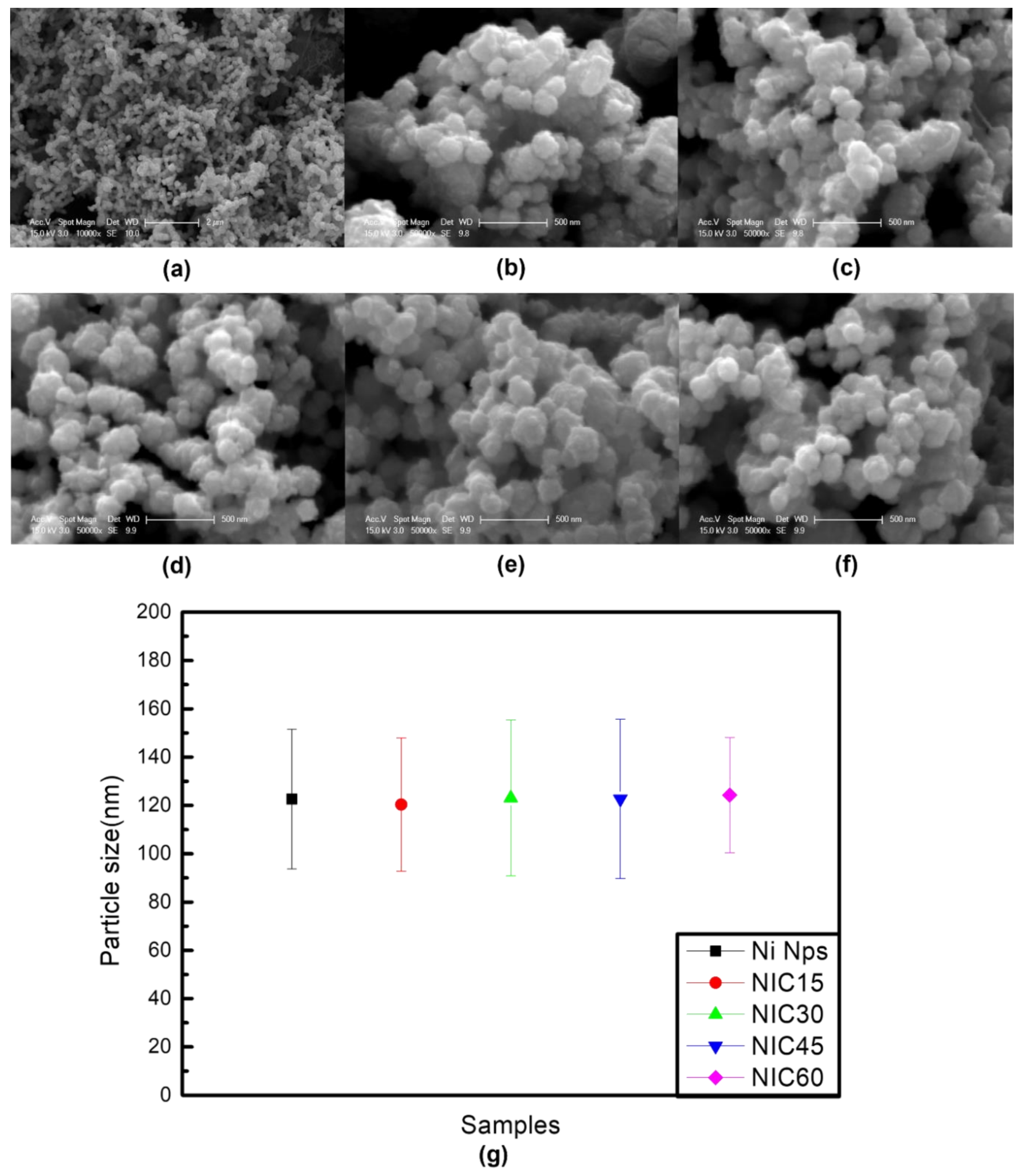
Figure 2.
(a–d) EDS data of NICs prepared using TEG at carburizing process times of 15, 30, 45, and 60 min.
Figure 2.
(a–d) EDS data of NICs prepared using TEG at carburizing process times of 15, 30, 45, and 60 min.
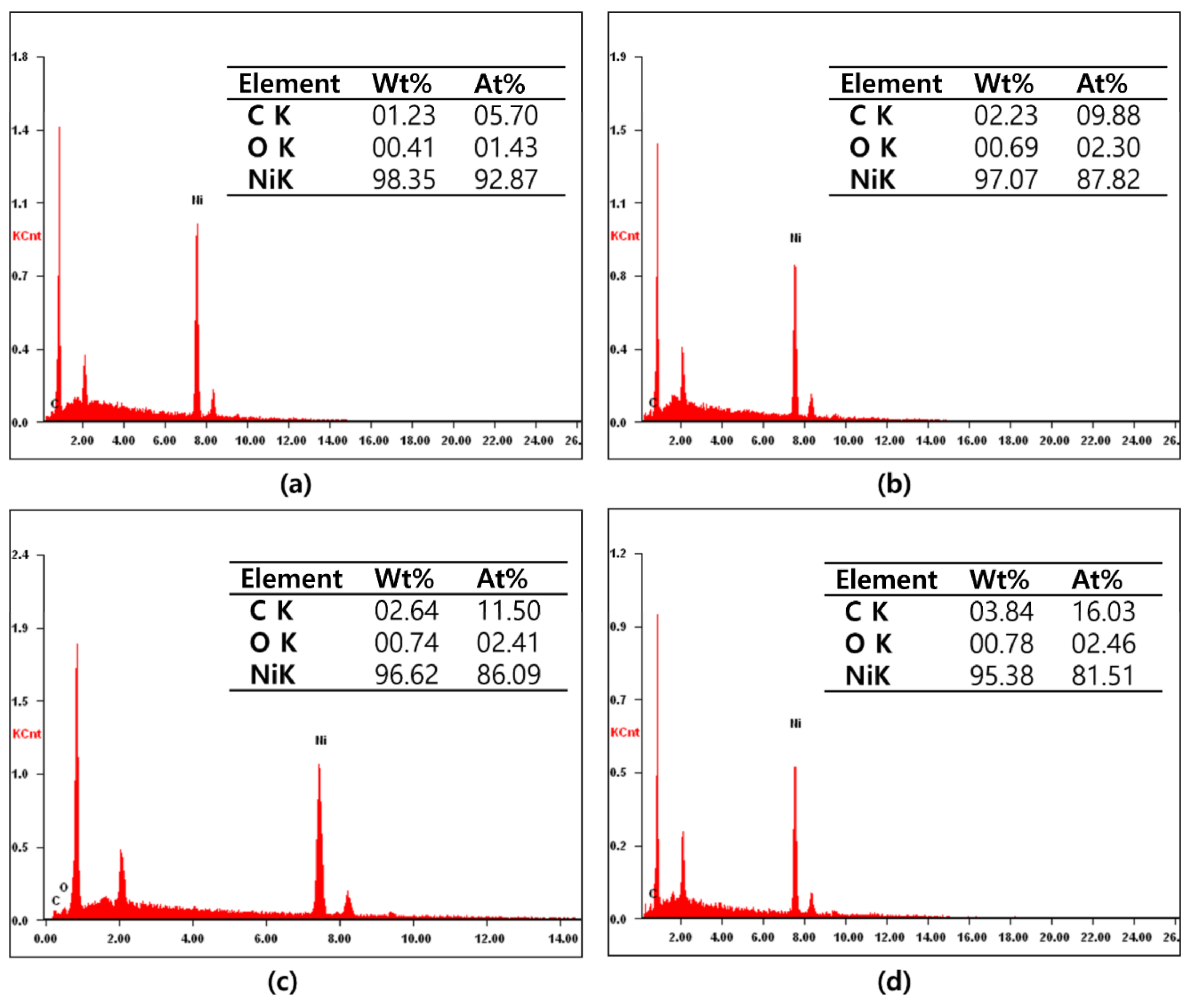
Figure 3.
(a) XRD data of Ni Nps and NICs. (b) Enlarged graph showing the major peaks of Ni and Ni3C.
Figure 3.
(a) XRD data of Ni Nps and NICs. (b) Enlarged graph showing the major peaks of Ni and Ni3C.
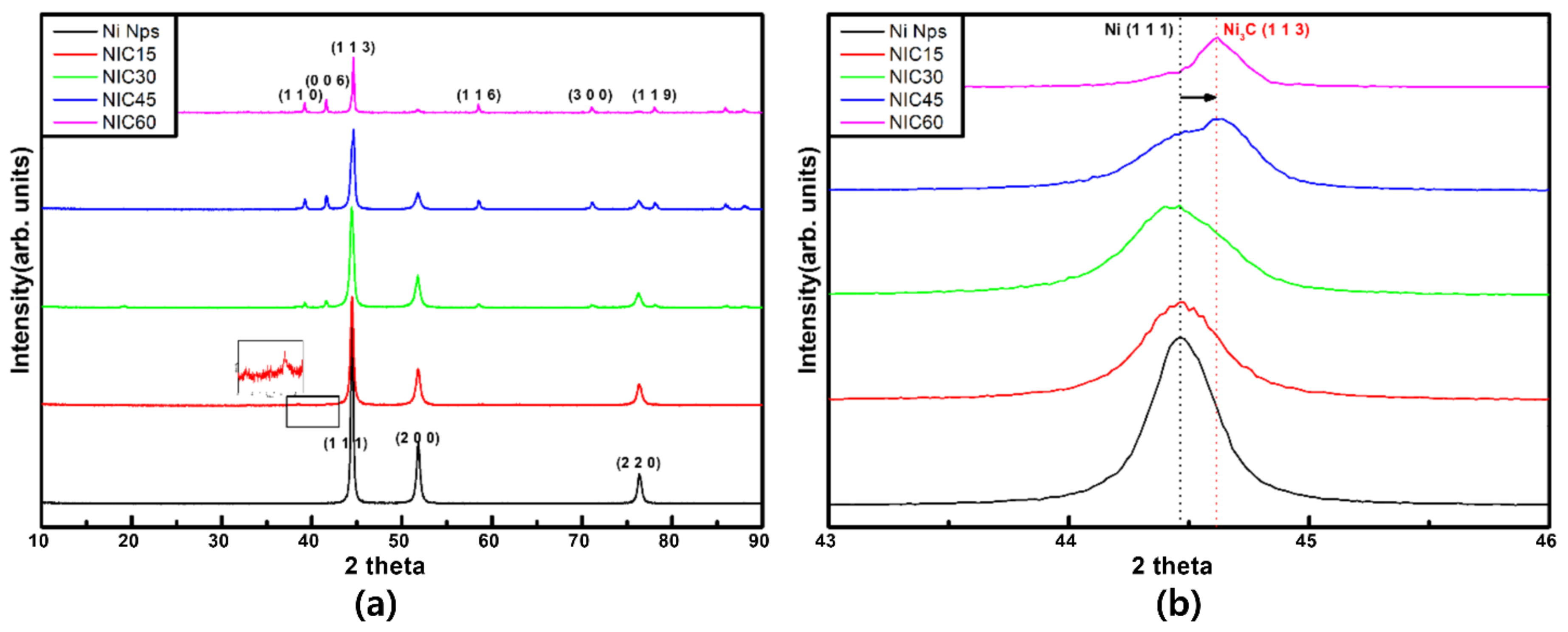
Figure 4.
TEM images of (a,f) Ni Nps, (b,g) NIC15, (c,h) NIC30, (d,i) NIC45, and (e,j) NIC60.

Figure 5.
TEM images and corresponding EDS elemental maps of (a) Ni Nps and (b) NIC60, revealing the spatial distribution of Ni and C elements. (c) Fast Fourier transform (FFT) of Ni Nps. (d) Fast Fourier transform (FFT) of NIC60.
Figure 5.
TEM images and corresponding EDS elemental maps of (a) Ni Nps and (b) NIC60, revealing the spatial distribution of Ni and C elements. (c) Fast Fourier transform (FFT) of Ni Nps. (d) Fast Fourier transform (FFT) of NIC60.
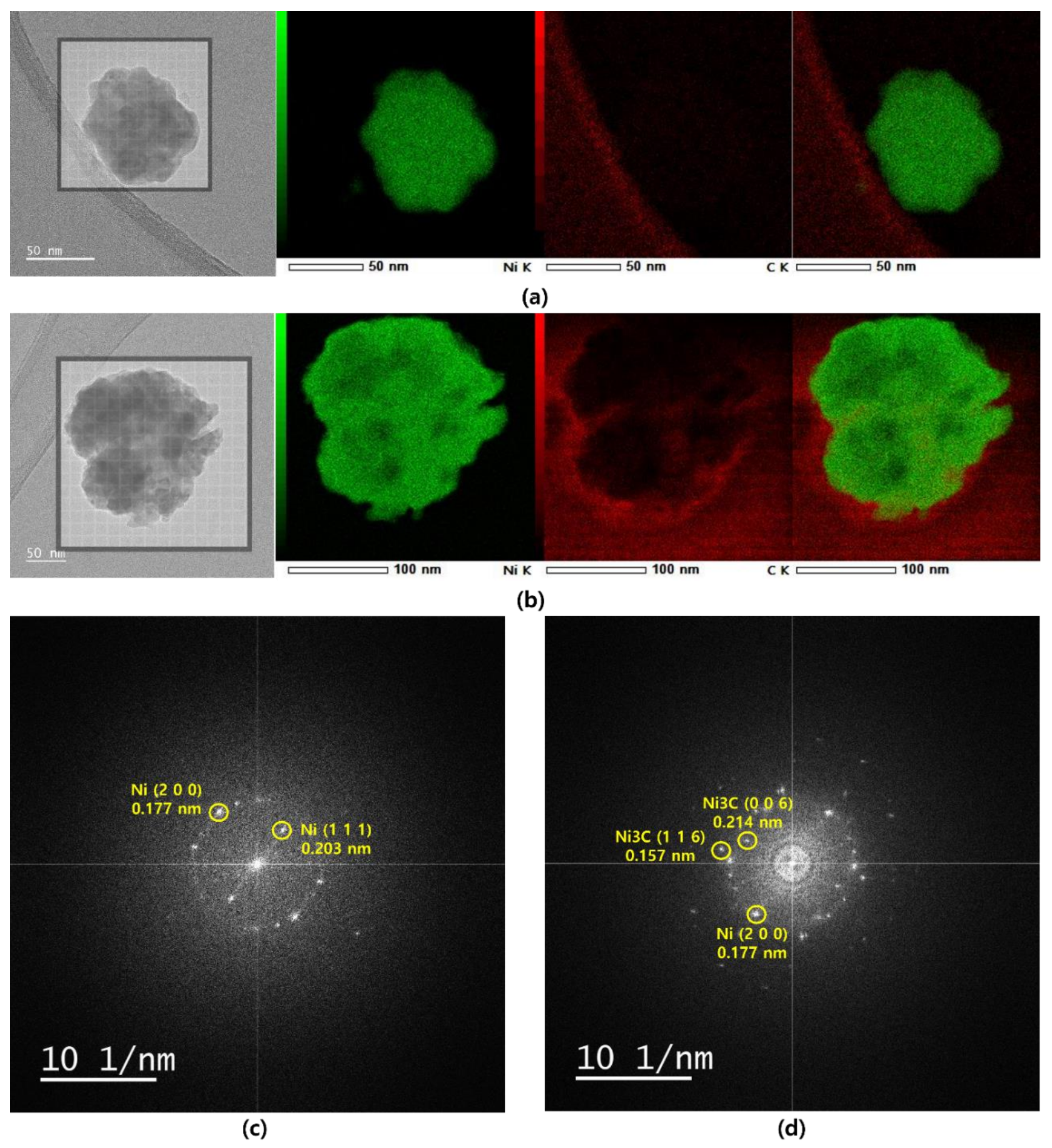
Figure 6.
XPS C1s data of (a) Ni Nps, (b) NIC15, (c) NIC30, (d) NIC45, and (e) NIC60. XPS Ni2P2/3 data of (f) Ni Nps, (g) NIC15, (h) NIC30, (i) NIC45, and (j) NIC60.
Figure 6.
XPS C1s data of (a) Ni Nps, (b) NIC15, (c) NIC30, (d) NIC45, and (e) NIC60. XPS Ni2P2/3 data of (f) Ni Nps, (g) NIC15, (h) NIC30, (i) NIC45, and (j) NIC60.
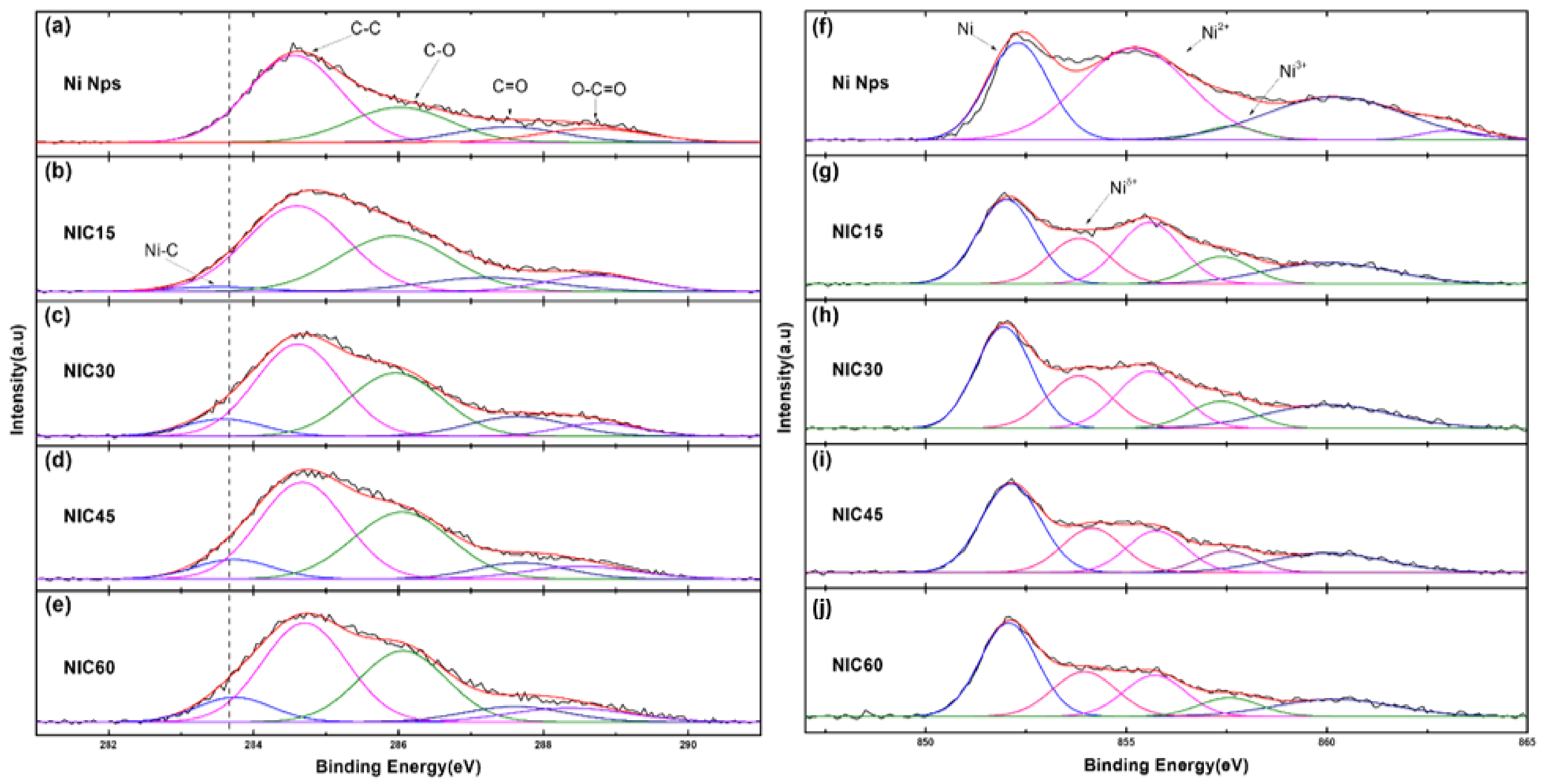
Figure 7.
Suggested growth mechanism of NICs.
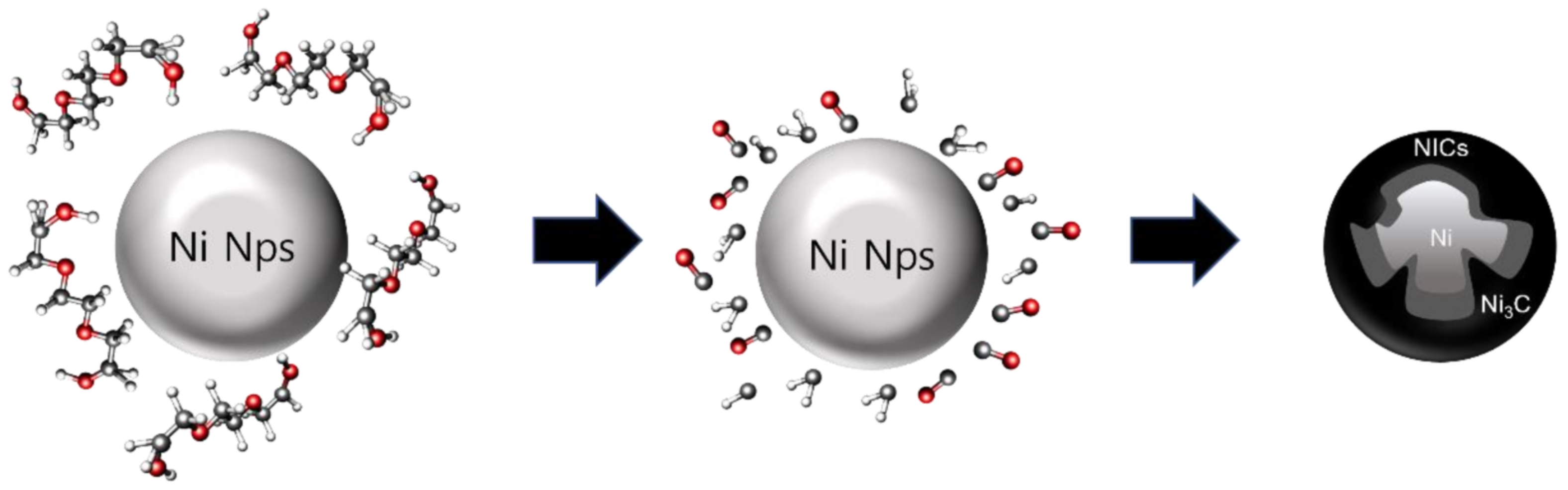
Figure 8.
Field-dependent magnetization (M−(H) curves) of Ni Nps and NICs at 300 K.

Publisher’s Note: MDPI stays neutral with regard to jurisdictional claims in published maps and institutional affiliations. |
© 2022 by the authors. Licensee MDPI, Basel, Switzerland. This article is an open access article distributed under the terms and conditions of the Creative Commons Attribution (CC BY) license (https://creativecommons.org/licenses/by/4.0/).
Share and Cite
MDPI and ACS Style
Kim, S.-W.; Ro, J.C.; Suh, S.-J. Simple Synthesis and Characterization of Shell-Thickness-Controlled Ni/Ni3C Core-Shell Nanoparticles. Nanomaterials 2022, 12, 1954. https://doi.org/10.3390/nano12121954
AMA Style
Kim S-W, Ro JC, Suh S-J. Simple Synthesis and Characterization of Shell-Thickness-Controlled Ni/Ni3C Core-Shell Nanoparticles. Nanomaterials. 2022; 12(12):1954. https://doi.org/10.3390/nano12121954
Chicago/Turabian StyleKim, Sun-Woo, Jae Chul Ro, and Su-Jeong Suh. 2022. "Simple Synthesis and Characterization of Shell-Thickness-Controlled Ni/Ni3C Core-Shell Nanoparticles" Nanomaterials 12, no. 12: 1954. https://doi.org/10.3390/nano12121954
Note that from the first issue of 2016, this journal uses article numbers instead of page numbers. See further details here.