
Environmentally Compatible Lead-Free Perovskite Solar Cells and Their Potential as Light Harvesters in Energy Storage Systems

 ,
, 

Abstract
:1. Introduction
2. Development of Pb-Free Sn-Based Perovskite Solar Cells
2.1. Pb-Free Sn-Based Perovskite Solar Cells at Their Infancy
2.2. Burgeoning of Sn-Based Perovskite Solar Cells via Mixing Cations in Inverted Architecture
2.2.1. A-Site Cation Engineering in Sn-Based Perovskite Solar Cells
2.3. Sequential Deposition Technique as the Game Changer
2.4. Doping Sn Perovskites Using Additives
2.5. High Performance All-Inorganic Sn Perovskite Solar Cells
2.6. Anti-Oxidation as the Key to Improving VOC and Device Stability
2.7. Energy Level Alignment as the Key to Improving VOC
2.8. Lead-Free Sn PSCs as Photo-Charging Power Source
3. Conclusions
Funding
Acknowledgments
Conflicts of Interest
References
- Kojima, A.; Teshima, K.; Shirai, Y.; Miyasaka, T. Organometal Halide Perovskites as Visible-Light Sensitizers for Photovoltaic Cells. J. Am. Chem. Soc. 2009, 131, 6050–6051. [Google Scholar] [CrossRef] [PubMed]
- Kim, H.-S.; Lee, C.-R.; Im, J.-H.; Lee, K.-B.; Moehl, T.; Marchioro, A.; Moon, S.-J.; Humphry-Baker, R.; Yum, J.-H.; Moser, J.E.; et al. Lead Iodide Perovskite Sensitized All-Solid-State Submicron Thin Film Mesoscopic Solar Cell with Efficiency Exceeding 9%. Sci. Rep. 2012, 2, 591. [Google Scholar] [CrossRef] [PubMed] [Green Version]
- Lee, M.M.; Teuscher, J.; Miyasaka, T.; Murakami, T.N.; Snaith, H.J. Efficient Hybrid Solar Cells Based on Meso-Superstructured Organometal Halide Perovskites. Science 2012, 338, 643–647. [Google Scholar] [CrossRef] [PubMed] [Green Version]
- Xing, G.; Mathews, N.; Sun, S.; Lim, S.S.; Lam, Y.M.; Gratzel, M.; Mhaisalkar, S.; Sum, T.C. Long-Range Balanced Electron- and Hole-Transport Lengths in Organic-Inorganic CH3NH3PbI3. Science 2013, 342, 344–347. [Google Scholar] [CrossRef] [PubMed]
- Lee, J.-W.; Seol, D.-J.; Cho, A.-N.; Park, N.-G. High-Efficiency Perovskite Solar Cells Based on the Black Polymorph of HC(NH2) 2PbI3. Adv. Mater. 2014, 26, 4991–4998. [Google Scholar] [CrossRef] [PubMed]
- Yin, W.-J.; Shi, T.; Yan, Y. Unusual defect physics in CH3NH3PbI3 perovskite solar cell absorber. Appl. Phys. Lett. 2014, 104, 063903. [Google Scholar] [CrossRef]
- Jeong, M.; Choi, I.W.; Go, E.M.; Cho, Y.; Kim, M.; Lee, B.; Jeong, S.; Jo, Y.; Choi, H.W.; Lee, J.; et al. Stable perovskite solar cells with efficiency exceeding 24.8% and 0.3-V voltage loss. Science 2020, 369, 1615–1620. [Google Scholar] [CrossRef]
- Jeong, J.; Kim, M.; Seo, J.; Lu, H.; Ahlawat, P.; Mishra, A.; Yang, Y.; Hope, M.A.; Eickemeyer, F.T.; Kim, M.; et al. Pseudo-halide anion engineering for α-FAPbI3 perovskite solar cells. Nature 2021, 592, 381–385. [Google Scholar] [CrossRef]
- Min, H.; Kim, M.; Lee, S.-U.; Kim, H.; Kim, G.; Choi, K.; Lee, J.H.; Seok, S., II. Efficient, stable solar cells by using inherent bandgap of α-phase formamidinium lead iodide. Science 2019, 366, 749–753. [Google Scholar] [CrossRef]
- Kim, M.; Kim, G.-H.; Lee, T.K.; Choi, I.W.; Choi, H.W.; Jo, Y.; Yoon, Y.J.; Kim, J.W.; Lee, J.; Huh, D.; et al. Methylammonium Chloride Induces Intermediate Phase Stabilization for Efficient Perovskite Solar Cells. Joule 2019, 3, 2179–2192. [Google Scholar] [CrossRef]
- Jeon, I.; Shawky, A.; Lin, H.-S.H.-S.; Seo, S.; Okada, H.; Lee, J.-W.J.-W.; Pal, A.; Tan, S.; Anisimov, A.; Kauppinen, E.I.E.I.; et al. Controlled Redox of Lithium-Ion Endohedral Fullerene for Efficient and Stable Metal Electrode-Free Perovskite Solar Cells. J. Am. Chem. Soc. 2019, 141, 16553–16558. [Google Scholar] [CrossRef]
- Jeon, I.; Ueno, H.; Seo, S.; Aitola, K.; Nishikubo, R.; Saeki, A.; Okada, H.; Boschloo, G.; Maruyama, S.; Matsuo, Y. Lithium-Ion Endohedral Fullerene (Li + @C60) Dopants in Stable Perovskite Solar Cells Induce Instant Doping and Anti-Oxidation. Angew. Chem. Int. Ed. 2018, 57, 4607–4611. [Google Scholar] [CrossRef]
- Lyu, M.; Yun, J.-H.; Chen, P.; Hao, M.; Wang, L. Addressing Toxicity of Lead: Progress and Applications of Low-Toxic Metal Halide Perovskites and Their Derivatives. Adv. Energy Mater. 2017, 7, 1602512. [Google Scholar] [CrossRef]
- Abate, A. Perovskite Solar Cells Go Lead Free. Joule 2017, 1, 659–664. [Google Scholar] [CrossRef] [Green Version]
- Hu, H.; Dong, B.; Zhang, W. Low-toxic metal halide perovskites: Opportunities and future challenges. J. Mater. Chem. A 2017, 5, 11436–11449. [Google Scholar] [CrossRef]
- Mahaffey, K.R. Environmental lead toxicity: Nutrition as a component of intervention. Environ. Health Perspect. 1990, 89, 75–78. [Google Scholar] [CrossRef] [PubMed]
- Wani, A.L.; Ara, A.; Usmani, J.A. Lead toxicity: A review. Interdiscip. Toxicol. 2015, 8, 55–64. [Google Scholar] [CrossRef] [Green Version]
- Li, X.; Zhang, F.; He, H.; Berry, J.J.; Zhu, K.; Xu, T. On-device lead sequestration for perovskite solar cells. Nature 2020, 578, 555–558. [Google Scholar] [CrossRef]
- Serrano-Lujan, L.; Espinosa, N.; Larsen-Olsen, T.T.; Abad, J.; Urbina, A.; Krebs, F.C. Tin- and Lead-Based Perovskite Solar Cells under Scrutiny: An Environmental Perspective. Adv. Energy Mater. 2015, 5, 1501119. [Google Scholar] [CrossRef]
- Ke, W.; Stoumpos, C.C.; Kanatzidis, M.G. “Unleaded” Perovskites: Status Quo and Future Prospects of Tin-Based Perovskite Solar Cells. Adv. Mater. 2019, 31, 1803230. [Google Scholar] [CrossRef]
- Giustino, F.; Snaith, H.J. Toward Lead-Free Perovskite Solar Cells. ACS Energy Lett. 2016, 1, 1233–1240. [Google Scholar] [CrossRef] [Green Version]
- Stoumpos, C.C.; Malliakas, C.D.; Kanatzidis, M.G. Semiconducting Tin and Lead Iodide Perovskites with Organic Cations: Phase Transitions, High Mobilities, and Near-Infrared Photoluminescent Properties. Inorg. Chem. 2013, 52, 9019–9038. [Google Scholar] [CrossRef] [PubMed]
- Hao, F.; Stoumpos, C.C.; Cao, D.H.; Chang, R.P.H.; Kanatzidis, M.G. Lead-free solid-state organic–inorganic halide perovskite solar cells. Nat. Photonics 2014, 8, 489–494. [Google Scholar] [CrossRef]
- Noel, N.K.; Stranks, S.D.; Abate, A.; Wehrenfennig, C.; Guarnera, S.; Haghighirad, A.-A.A.; Sadhanala, A.; Eperon, G.E.; Pathak, S.K.; Johnston, M.B.; et al. Lead-Free Organic-Inorganic Tin Halide Perovskites for Photovoltaic Applications. Energy Environ. Sci. 2014, 7, 3061–3068. [Google Scholar] [CrossRef]
- Diau, E.W.-G.; Jokar, E.; Rameez, M. Strategies to Improve Performance and Stability for Tin-Based Perovskite Solar Cells. ACS Energy Lett. 2019, 4, 1930–1937. [Google Scholar] [CrossRef]
- Liao, W.; Zhao, D.; Yu, Y.; Grice, C.R.; Wang, C.; Cimaroli, A.J.; Schulz, P.; Meng, W.; Zhu, K.; Xiong, R.; et al. Lead-Free Inverted Planar Formamidinium Tin Triiodide Perovskite Solar Cells Achieving Power Conversion Efficiencies up to 6.22%. Adv. Mater. 2016, 28, 9333–9340. [Google Scholar] [CrossRef]
- Song, T.B.; Yokoyama, T.; Stoumpos, C.C.; Logsdon, J.; Cao, D.H.; Wasielewski, M.R.; Aramaki, S.; Kanatzidis, M.G. Importance of reducing vapor atmosphere in the fabrication of Tin-based perovskite solar cells. J. Am. Chem. Soc. 2017, 139, 836–842. [Google Scholar] [CrossRef]
- Lee, S.J.; Shin, S.S.; Kim, Y.C.; Kim, D.; Ahn, T.K.; Noh, J.H.; Seo, J.; Seok, S., II. Fabrication of Efficient Formamidinium Tin Iodide Perovskite Solar Cells through SnF2–Pyrazine Complex. J. Am. Chem. Soc. 2016, 138, 3974–3977. [Google Scholar] [CrossRef] [PubMed]
- Ke, W.; Stoumpos, C.C.; Zhu, M.; Mao, L.; Spanopoulos, I.; Liu, J.; Kontsevoi, O.Y.; Chen, M.; Sarma, D.; Zhang, Y.; et al. Enhanced photovoltaic performance and stability with a new type of hollow 3D perovskite {en}FASnI3. Sci. Adv. 2017, 3, e1701293. [Google Scholar] [CrossRef] [Green Version]
- Zhao, Z.; Gu, F.; Li, Y.; Sun, W.; Ye, S.; Rao, H.; Liu, Z.; Bian, Z.; Huang, C. Mixed-Organic-Cation Tin Iodide for Lead-Free Perovskite Solar Cells with an Efficiency of 8.12%. Adv. Sci. 2017, 4. [Google Scholar] [CrossRef] [Green Version]
- Shao, S.; Liu, J.; Portale, G.; Fang, H.H.; Blake, G.R.; Brink, G.H.t.; Koster, L.J.A.; Loi, M.A. Highly Reproducible Sn-Based Hybrid Perovskite Solar Cells with 9% Efficiency. Adv. Energy Mater. 2018, 8, 1702019. [Google Scholar] [CrossRef]
- Zhu, Z.; Chueh, C.C.; Li, N.; Mao, C.; Jen, A.K.Y. Realizing Efficient Lead-Free Formamidinium Tin Triiodide Perovskite Solar Cells via a Sequential Deposition Route. Adv. Mater. 2018, 30, 1703800. [Google Scholar] [CrossRef]
- Shahbazi, S.; Li, M.-Y.; Fathi, A.; Diau, E.W.-G. Realizing a Cosolvent System for Stable Tin-Based Perovskite Solar Cells Using a Two-Step Deposition Approach. ACS Energy Lett. 2020, 5, 2508–2511. [Google Scholar] [CrossRef]
- Jokar, E.; Chien, C.H.; Fathi, A.; Rameez, M.; Chang, Y.H.; Diau, E.W.G. Slow surface passivation and crystal relaxation with additives to improve device performance and durability for tin-based perovskite solar cells. Energy Environ. Sci. 2018, 11, 2353–2362. [Google Scholar] [CrossRef]
- Ito, N.; Kamarudin, M.A.; Hirotani, D.; Zhang, Y.; Shen, Q.; Ogomi, Y.; Iikubo, S.; Minemoto, T.; Yoshino, K.; Hayase, S. Mixed Sn-Ge Perovskite for Enhanced Perovskite Solar Cell Performance in Air. J. Phys. Chem. Lett. 2018, 9, 1682–1688. [Google Scholar] [CrossRef]
- Liu, J.; Ozaki, M.; Yakumaru, S.; Handa, T.; Nishikubo, R.; Kanemitsu, Y.; Saeki, A.; Murata, Y.; Murdey, R.; Wakamiya, A. Lead-Free Solar Cells based on Tin Halide Perovskite Films with High Coverage and Improved Aggregation. Angew. Chem. Int. Ed. 2018, 57, 13221–13225. [Google Scholar] [CrossRef]
- Jokar, E.; Chien, C.H.; Tsai, C.M.; Fathi, A.; Diau, E.W.G. Robust Tin-Based Perovskite Solar Cells with Hybrid Organic Cations to Attain Efficiency Approaching 10%. Adv. Mater. 2019, 31, 1804835. [Google Scholar] [CrossRef]
- Meng, X.; Lin, J.; Liu, X.; He, X.; Wang, Y.; Noda, T.; Wu, T.; Yang, X.; Han, L. Highly Stable and Efficient FASnI3-Based Perovskite Solar Cells by Introducing Hydrogen Bonding. Adv. Mater. 2019, 31, 1903721. [Google Scholar] [CrossRef]
- Chen, M.; Ju, M.G.; Garces, H.F.; Carl, A.D.; Ono, L.K.; Hawash, Z.; Zhang, Y.; Shen, T.; Qi, Y.; Grimm, R.L.; et al. Highly stable and efficient all-inorganic lead-free perovskite solar cells with native-oxide passivation. Nat. Commun. 2019, 10, 1–8. [Google Scholar] [CrossRef] [PubMed] [Green Version]
- Kamarudin, M.A.; Hirotani, D.; Wang, Z.; Hamada, K.; Nishimura, K.; Shen, Q.; Toyoda, T.; Iikubo, S.; Minemoto, T.; Yoshino, K.; et al. Suppression of Charge Carrier Recombination in Lead-Free Tin Halide Perovskite via Lewis Base Post-treatment. J. Phys. Chem. Lett. 2019, 10, 5277–5283. [Google Scholar] [CrossRef]
- He, X.; Wu, T.; Liu, X.; Wang, Y.; Meng, X.; Wu, J.; Noda, T.; Yang, X.; Moritomo, Y.; Segawa, H.; et al. Highly efficient tin perovskite solar cells achieved in a wide oxygen concentration range. J. Mater. Chem. A 2020, 8, 2760–2768. [Google Scholar] [CrossRef]
- Chen, M.; Dong, Q.; Eickemeyer, F.T.; Liu, Y.; Dai, Z.; Carl, A.D.; Bahrami, B.; Chowdhury, A.H.; Grimm, R.L.; Shi, Y.; et al. High-Performance Lead-Free Solar Cells Based on Tin-Halide Perovskite Thin Films Functionalized by a Divalent Organic Cation. ACS Energy Lett. 2020, 5, 2223–2230. [Google Scholar] [CrossRef]
- Liu, X.; Wang, Y.; Wu, T.; He, X.; Meng, X.; Barbaud, J.; Chen, H.; Segawa, H.; Yang, X.; Han, L. Efficient and stable tin perovskite solar cells enabled by amorphous-polycrystalline structure. Nat. Commun. 2020, 11, 1–7. [Google Scholar] [CrossRef]
- Nakamura, T.; Yakumaru, S.; Truong, M.A.; Kim, K.; Liu, J.; Hu, S.; Otsuka, K.; Hashimoto, R.; Murdey, R.; Sasamori, T.; et al. Sn(IV)-free tin perovskite films realized by in situ Sn(0) nanoparticle treatment of the precursor solution. Nat. Commun. 2020, 11, 3008. [Google Scholar] [CrossRef] [PubMed]
- Jeon, I., II; Delacou, C.; Nakagawa, T.; Matsuo, Y.; Delacou, Ø.; Nakagawa, T.; Matsuo, Y. Enhancement of Open-Circuit Voltage by Using the 58-π Silylmethyl Fullerenes in Small-Molecule Organic Solar Cells. Chem. Asian J. 2016, 11, 1268–1272. [Google Scholar] [CrossRef] [PubMed]
- Pal, A.; Wen, L.K.L.K.; Jun, C.Y.C.Y.; Jeon, I.; Matsuo, Y.; Manzhos, S. Comparative density functional theory–density functional tight binding study of fullerene derivatives: Effects due to fullerene size, addends, and crystallinity on band structure, charge transport and optical properties. Phys. Chem. Chem. Phys. 2017, 19, 28330–28343. [Google Scholar] [CrossRef]
- Lin, H.-S.H.-S.; Jeon, I.; Chen, Y.; Yang, X.-Y.X.-Y.; Nakagawa, T.; Maruyama, S.; Manzhos, S.; Matsuo, Y. Highly Selective and Scalable Fullerene-Cation-Mediated Synthesis Accessing Cyclo[60]fullerenes with Five-Membered Carbon Ring and Their Application to Perovskite Solar Cells. Chem. Mater. 2019, 31, 8432–8439. [Google Scholar] [CrossRef]
- Ueno, H.; Jeon, I.; Lin, H.-S.; Thote, A.; Nakagawa, T.; Okada, H.; Izawa, S.; Hiramoto, M.; Daiguji, H.; Maruyama, S.; et al. Li@C60 endohedral fullerene as a supraatomic dopant for C60 electron-transporting layers promoting the efficiency of perovskite solar cells. Chem. Commun. 2019, 55, 11837–11839. [Google Scholar] [CrossRef]
- Delacou, C.; Jeon, I.; Otsuka, K.; Inoue, T.; Anisimov, A.; Fujii, T.; Kauppinen, E.I.; Maruyama, S.; Matsuo, Y. Investigation of charge interaction between fullerene derivatives and single-walled carbon nanotubes. InfoMat 2019, 1, 559–570. [Google Scholar] [CrossRef] [Green Version]
- Jiang, X.; Wang, F.; Wei, Q.; Li, H.; Shang, Y.; Zhou, W.; Wang, C.; Cheng, P.; Chen, Q.; Chen, L.; et al. Ultra-high open-circuit voltage of tin perovskite solar cells via an electron transporting layer design. Nat. Commun. 2020, 11, 1245. [Google Scholar] [CrossRef]
- Nishimura, K.; Kamarudin, M.A.; Hirotani, D.; Hamada, K.; Shen, Q.; Iikubo, S.; Minemoto, T.; Yoshino, K.; Hayase, S. Lead-free tin-halide perovskite solar cells with 13% efficiency. Nano Energy. 2020, 74, 104858. [Google Scholar] [CrossRef]
- Jokar, E.; Cheng, P.-Y.; Lin, C.-Y.; Narra, S.; Shahbazi, S.; Diau, E.W.-G. Enhanced Performance and Stability of 3D/2D Tin Perovskite Solar Cells Fabricated with a Sequential Solution Deposition. ACS Energy Lett. 2021, 6, 485–492. [Google Scholar] [CrossRef]
- Cui, D.; Liu, X.; Wu, T.; Lin, X.; Luo, X.; Wu, Y.; Segawa, H.; Yang, X.; Zhang, Y.; Wang, Y.; et al. Making Room for Growing Oriented FASnI3 with Large Grains via Cold Precursor Solution. Adv. Funct. Mater. 2021, 31, 2100931. [Google Scholar] [CrossRef]
- Xu, J.; Chen, Y.; Dai, L. Efficiently photo-charging lithium-ion battery by perovskite solar cell. Nat. Commun. 2015, 6, 8103. [Google Scholar] [CrossRef] [PubMed] [Green Version]
- Gurung, A.; Chen, K.; Khan, R.; Abdulkarim, S.S.; Varnekar, G.; Pathak, R.; Naderi, R.; Qiao, Q. Highly Efficient Perovskite Solar Cell Photocharging of Lithium Ion Battery Using DC-DC Booster. Adv. Energy Mater. 2017, 7, 1602105. [Google Scholar] [CrossRef]
- Li, C.; Cong, S.; Tian, Z.; Song, Y.; Yu, L.; Lu, C.; Shao, Y.; Li, J.; Zou, G.; Rümmeli, M.H.; et al. Flexible perovskite solar cell-driven photo-rechargeable lithium-ion capacitor for self-powered wearable strain sensors. Nano Energy 2019, 60, 247–256. [Google Scholar] [CrossRef]
- Lee, J.-W.; Jeon, I.; Lin, H.-S.; Seo, S.; Han, T.-H.; Anisimov, A.; Kauppinen, E.I.; Matsuo, Y.; Maruyama, S.; Yang, Y. Vapor-Assisted Ex-Situ Doping of Carbon Nanotube toward Efficient and Stable Perovskite Solar Cells. Nano Lett. 2019, 19, 2223–2230. [Google Scholar] [CrossRef] [PubMed]
- Jeon, I.; Xiang, R.; Shawky, A.; Matsuo, Y.; Maruyama, S. Single-Walled Carbon Nanotubes in Emerging Solar Cells: Synthesis and Electrode Applications. Adv. Energy Mater. 2019, 9, 1801312. [Google Scholar] [CrossRef]
- Jeon, I.; Shawky, A.; Seo, S.; Qian, Y.; Anisimov, A.; Kauppinen, E.I.; Matsuo, Y.; Maruyama, S. Carbon nanotubes to outperform metal electrodes in perovskite solar cells via dopant engineering and hole-selectivity enhancement. J. Mater. Chem. A 2020, 8, 11141–11147. [Google Scholar] [CrossRef]
- Jeon, I.; Matsuo, Y.; Maruyama, S. Single-Walled Carbon Nanotubes in Solar Cells. In Single-Walled Carbon Nanotubes. Topics in Current Chemistry Collections; Springer: Cham, Switzerland, 2018; Volume 376, pp. 271–298. [Google Scholar] [CrossRef]
- Liu, Y.; Gao, W.; Ran, C.; Dong, H.; Sun, N.; Ran, X.; Xia, Y.; Song, L.; Chen, Y.; Huang, W. All-inorganic Sn-based Perovskite Solar Cells: Status, Challenges, and Perspectives. ChemSusChem 2020, 13, 6477–6497. [Google Scholar] [CrossRef]
- Yan, Y.; Pullerits, T.; Zheng, K.; Liang, Z. Advancing Tin Halide Perovskites: Strategies toward the ASnX3 Paradigm for Efficient and Durable Optoelectronics. ACS Energy Lett. 2020, 5, 2052–2086. [Google Scholar] [CrossRef]
- Tao, S.; Schmidt, I.; Brocks, G.; Jiang, J.; Tranca, I.; Meerholz, K.; Olthof, S. Absolute energy level positions in tin- and lead-based halide perovskites. Nat. Commun. 2019, 10, 2560. [Google Scholar] [CrossRef] [PubMed]

| Report | Year [Ref.] | Device Structure | JSC [mA m−2] | VOC [V] | FF | PCE [%] |
|---|---|---|---|---|---|---|
| A | 2016 [26] | Glass/ITO/PEDOT:PSS/FASnI3/C60/BCP/Ag | 22.07 | 0.47 | 0.60 | 6.22 |
| B | 2016 [27] | Glass/FTO/c-TiO2/m-TiO2/MASnI3/PTAA/Au | 19.92 | 0.38 | 0.51 | 3.86 |
| C | 2016 [28] | Glass/FTO/c-TiO2/m-TiO2/FASnI3/spiro-MeOTAD/Au | 23.70 | 0.32 | 0.63 | 4.80 |
| D | 2017 [29] | Glass/FTO/c-TiO2/m-TiO2/{en}FASnI3/spiro-MeOTAD/Au | 22.54 | 0.48 | 0.66 | 7.14 |
| Report | Year [Ref.] | Device Structure | JSC [mA m−2] | VOC [V] | FF | PCE [%] |
|---|---|---|---|---|---|---|
| E | 2017 [30] | Glass/ITO/PEDOT:PSS/FA0.75MA0.25SnI3/ C60/BCP/Ag | 21.20 | 0.61 | 0.63 | 8.12 |
| Report | Year [Ref.] | Device Structure | JSC [mA m−2] | VOC [V] | FF | PCE [%] |
|---|---|---|---|---|---|---|
| F | 2018 [31] | Glass/ITO/PEDOT:PSS/FASnI3 (PEAI)/C60/ BCP/Ag | 24.1 | 0.53 | 0.71 | 9.00 |
| Report | Year [Ref.] | Device Structure | JSC [mA m−2] | VOC [V] | FF | PCE [%] |
|---|---|---|---|---|---|---|
| G | 2018 [32] | Glass/ITO/PEDOT:PSS/FASnI3/C60/BCP/Ag | 22.45 | 0.47 | 0.68 | 7.09 |
| Report | Year [Ref.] | Device Structure | JSC [mA m−2] | VOC [V] | FF | PCE [%] |
|---|---|---|---|---|---|---|
| H | 2018 [34] | Glass/ITO/PEDOT:PSS/FASnI3 (1%EDAI2)/C60/BCP/Ag | 21.30 | 0.58 | 0.72 | 8.9 |
| I | 2018 [35] | Glass/ITO/PEDOT:PSS/FA0.75MA0.25Sn1-xGexI3/C60/BCP/Ag | 21.90 | 0.45 | 0.70 | 6.90 |
| J | 2018 [36] | Glass/ITO/PEDOT:PSS/FA0.75MA0.25SnI3/ C60/BCP/Ag | 19.40 | 0.55 | 0.61 | 7.20 |
| K | 2019 [37] | Glass/ITO/PEDOT:PSS/GAxFA0.98-xSnI3 (1%EDAI2)/C60/BCP/Ag | 21.20 | 0.62 | 0.73 | 9.60 |
| L | 2019 [38] | Glass/ITO/PEDOT:PSS/FASnI3-PVA/C60/BCP/Ag | 20.37 | 0.63 | 0.69 | 8.92 |
| Report | Year [Ref.] | Device Structure | JSC [mA m−2] | VOC [V] | FF | PCE [%] |
|---|---|---|---|---|---|---|
| M | 2019 [39] | Glass/FTO/PCBM/CsSn0.5Ge0.5I3/spiro-MeOTAD/Au | 18.61 | 0.63 | 0.61 | 7.11 |
| Report | Year [Ref.] | Device Structure | JSC [mA m−2] | VOC [V] | FF | PCE [%] |
|---|---|---|---|---|---|---|
| N | 2019 [40] | Glass/FTO/PEDOT:PSS/FA0.98EDA0.01SnI3/C60/BCP/Ag/Au | 23.09 | 0.60 | 0.73 | 10.18 |
| O | 2020 [41] | Glass/ITO/PEDOT:PSS/FASnI3-FBH/C60/BCP/Ag | 21.10 | 0.60 | 0.75 | 9.47 |
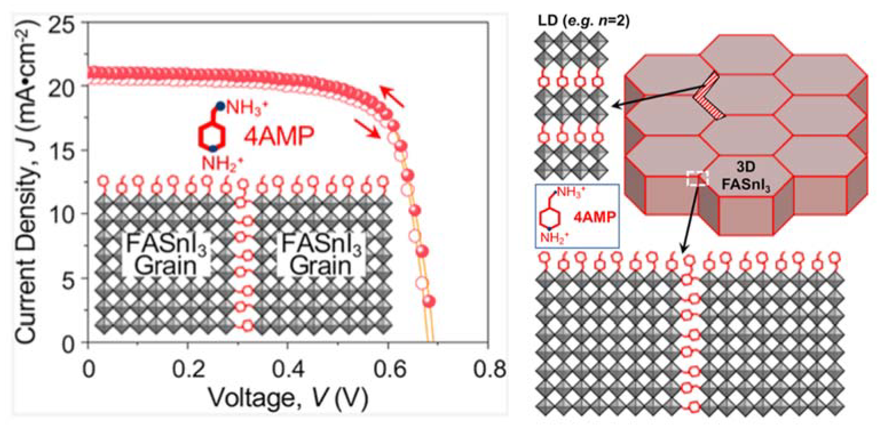
| P | 2020 [42] | Glass/FTO/Cu-NiOx/FASnI3-4AMP /PCBM/BCP/Ag | 21.15 | 0.69 | 0.74 | 10.86 |
| Q | 2020 [43] | Glass/FTO/PEDOT:PSS/CsFASnI3/PCBM/BCP/Ag | 21.60 | 0.64 | 0.75 | 10.40 |
| R | 2020 [44] | Glass/ITO/PEDOT:PSS/FA0.75MA0.25SnI3/PCBM/C60/BCP/Ag | 22.0 | 0.76 | 0.69 | 11.50 |
| Report | Year [Ref.] | Device Structure | JSC [mA m−2] | VOC [V] | FF | PCE [%] |
|---|---|---|---|---|---|---|
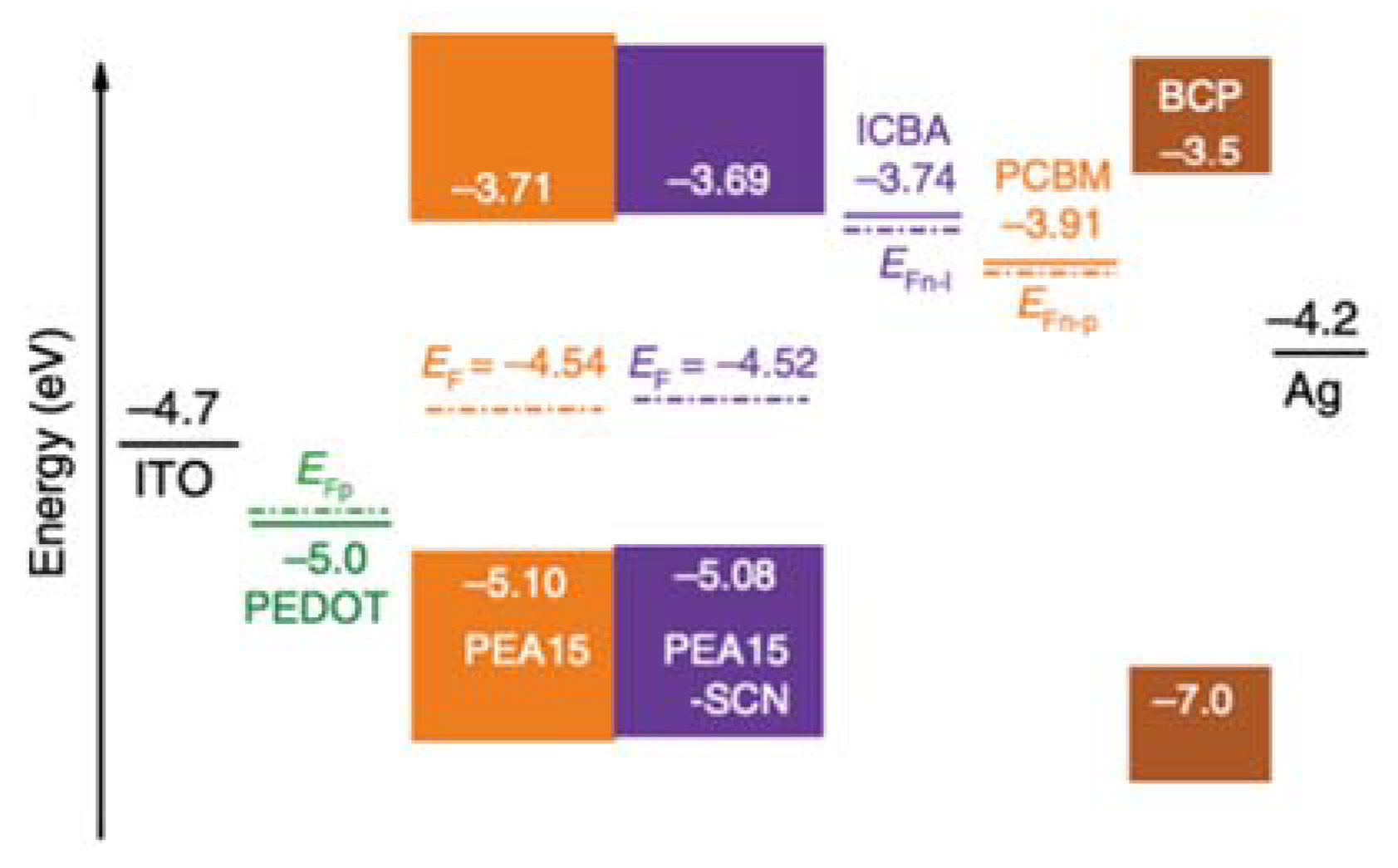
| S | 2020 [50] | Glass/ITO/PEDOT:PSS/PEA15-SCN FASnI3 /ICBA/BCP/Ag | 17.40 | 0.94 | 0.75 | 12.40 |
| T | 2020 [51] | Glass/FTO/PEDOT:PSS/Ge doped FA0.98EDA0.01SnI3 (EA 0.1)/ C60/BCP/Ag/Au | 20.32 | 0.84 | 0.78 | 13.24 |
| U | 2021 [52] | Glass/ITO/PEDOT:PSS/FA0.8GA0.2SnI3/BAC2SnI4/C60/BCP/Ag | 21.1 | 0.65 | 0.76 | 10.60 |
| V | 2021 [53] | Glass/ITO/PEDOT:PSS/FASnI3 (PAI)/C60/BCP/Ag | 22.48 | 0.77 | 0.70 | 12.11 |
Publisher’s Note: MDPI stays neutral with regard to jurisdictional claims in published maps and institutional affiliations. |
© 2021 by the authors. Licensee MDPI, Basel, Switzerland. This article is an open access article distributed under the terms and conditions of the Creative Commons Attribution (CC BY) license (https://creativecommons.org/licenses/by/4.0/).
Share and Cite
Jeon, I.; Kim, K.; Jokar, E.; Park, M.; Lee, H.-W.; Diau, E.W.-G. Environmentally Compatible Lead-Free Perovskite Solar Cells and Their Potential as Light Harvesters in Energy Storage Systems. Nanomaterials 2021, 11, 2066. https://doi.org/10.3390/nano11082066
Jeon I, Kim K, Jokar E, Park M, Lee H-W, Diau EW-G. Environmentally Compatible Lead-Free Perovskite Solar Cells and Their Potential as Light Harvesters in Energy Storage Systems. Nanomaterials. 2021; 11(8):2066. https://doi.org/10.3390/nano11082066
Chicago/Turabian StyleJeon, Il, Kyusun Kim, Efat Jokar, Minjoon Park, Hyung-Woo Lee, and Eric Wei-Guang Diau. 2021. "Environmentally Compatible Lead-Free Perovskite Solar Cells and Their Potential as Light Harvesters in Energy Storage Systems" Nanomaterials 11, no. 8: 2066. https://doi.org/10.3390/nano11082066
APA StyleJeon, I., Kim, K., Jokar, E., Park, M., Lee, H.-W., & Diau, E. W.-G. (2021). Environmentally Compatible Lead-Free Perovskite Solar Cells and Their Potential as Light Harvesters in Energy Storage Systems. Nanomaterials, 11(8), 2066. https://doi.org/10.3390/nano11082066