Article

Effect of Back-Gate Voltage on the High-Frequency Performance of Dual-Gate MoS2 Transistors

1
School of Electronic Information, University of Electronic Science and Technology of China Zhongshan Institute, Zhongshan 528402, China
2
School of Information and Communication Engineering, University of Electronic Science and Technology of China, Chengdu 611731, China
*
Author to whom correspondence should be addressed.
Nanomaterials 2021, 11(6), 1594; https://doi.org/10.3390/nano11061594
Submission received: 30 May 2021 / Revised: 14 June 2021 / Accepted: 15 June 2021 / Published: 17 June 2021
(This article belongs to the Special Issue Nanotechnology for Electronic Materials and Devices)

Abstract

:
As an atomically thin semiconductor, 2D molybdenum disulfide (MoS2) has demonstrated great potential in realizing next-generation logic circuits, radio-frequency (RF) devices and flexible electronics. Although various methods have been performed to improve the high-frequency characteristics of MoS2 RF transistors, the impact of the back-gate bias on dual-gate MoS2 RF transistors is still unexplored. In this work, we study the effect of back-gate control on the static and RF performance metrics of MoS2 high-frequency transistors. By using high-quality chemical vapor deposited bilayer MoS2 as channel material, high-performance top-gate transistors with on/off ratio of 107 and on-current up to 179 μA/μm at room temperature were realized. With the back-gate modulation, the source and drain contact resistances decrease to 1.99 kΩ∙μm at Vbg = 3 V, and the corresponding on-current increases to 278 μA/μm. Furthermore, both cut-off frequency and maximum oscillation frequency improves as the back-gate voltage increases to 3 V. In addition, a maximum intrinsic fmax of 29.7 GHz was achieved, which is as high as 2.1 times the fmax without the back-gate bias. This work provides significant insights into the influence of back-gate voltage on MoS2 RF transistors and presents the potential of dual-gate MoS2 RF transistors for future high-frequency applications.

1. Introduction

Since the first exfoliation of atomically thin graphene [1], two dimensional (2D) materials have demonstrated a wide range of remarkable properties for applications in future ubiquitous electronics [2,3]. Compared to bulk materials, their atomic-scale thickness provides a greater degree of electrostatic control, demonstrating the possibility of ultra-short channel devices with low power consumption [4]. As the most widely studied 2D material, graphene has shown great potential for device applications including high-frequency electronics, flexible electronics, spintronics, nanoelectromechanical systems, and energy storage due to its unique physical properties [5,6,7,8,9,10,11,12]. However, graphene does not have a band gap to limit its application in digital logic devices, and it also limits the maximum oscillation frequency of graphene radio-frequency (RF) transistors. Although band gap can be opened in graphene by artificial nanostructuring, chemical functionalization, etc., those processes add extra complexities with respect to practical applications [13]. Alternatively, another class of 2D material, called transition metal dichalcogenides (TMDCs) (MoS2, WS2, MoSe2, and WSe2), not only exhibits many graphene-like properties, such as mechanical flexibility, electrical properties, chemical stability, and the absence of dangling bonds, but also possesses a substantial band gap. TMDCs benefit from a rich pool of elements, and thus they can significantly adjust their electrical properties from metal to semiconductor by forming different compounds. A distinct feature of TMDC semiconductors is that the corresponding energy band structure changes from an indirect band gap to a direct band gap when the material thickness decreases from bulk material to monolayer. They show a wide range of bandgap modulation capability because of rich choices of chemical components, which enables the electronic application of various kinds. As the most studied TMDC material, MoS2 has a non-zero band gap structure similar to bulk silicon, making it an ideal choice for making next-generation electronic and optoelectronic applications [4,14,15,16,17,18,19,20].
With technological advancements, the high-frequency performance of MoS2 devices has attracted tremendous attention [16,18,21,22,23,24]. The high-frequency performance of MoS2 RF transistors has been improved through optimizing structure such as self-aligned gate, embedded gate and edge-contacted, etc. [24,25,26]. In 2014, exfoliated MoS2 RF transistors with self-aligned gate demonstrated intrinsic cut-off frequency fT of 42 GHz and maximum oscillation frequency fmax of 50 GHz were reported [25]. In 2015, Krasnozhon et al. introduced edge-contacted in exfoliated trilayer MoS2 RF transistors, obtaining a high extrinsic fT of 6 GHz and intrinsic fT of 25 GHz [26]. In 2017, with an optimized embedded gate structure, chemical vapor deposition (CVD) monolayer MoS2 transistors with extrinsic fT of 3.3 GHz and fmax of 9.8 GHz were fabricated [24]. In 2018, based on high-quality CVD bilayer MoS2, high-frequency MoS2 transistors with extrinsic maximum oscillation frequency of 23 GHz were demonstrated [16]. Gigahertz frequency mixer and amplifier based on MoS2 high-frequency transistors were also constructed for potential RF circuit applications [16,27]. Those works demonstrated the potential of 2D MoS2 for future novel high-frequency electronics. Although the high-frequency performance of MoS2 RF transistors has made exciting advances, its cutoff frequency and maximum oscillation frequency are still lower than those of modern Si transistors, and the high-frequency performance of dual-gate MoS2 transistors has not yet been reported.
In this dual-gate structure, the source and drain contact resistances can be modulated via the back-gate voltage, and the influence of the contact resistance on the direct-current (DC) and high-frequency performance of the device can be clearly resolved [28]. Bolshakov et al. presented a near-ideal subthreshold swing of ~60 mV/dec and a high field effect mobility of 100 cm2/Vs based on dual-gate MoS2 transistors with sub−10 nm top-gate dielectrics [29]. Lee et al. modulated the contact resistance and threshold voltage of dual-gate MoS2 transistors with h-BN as gate dielectric through back-gate electrostatic doping [30]. Li et al. demonstrated a high photoresponsivity of 2.04 × 10⁵ AW−1 with dual-gate MoS2 phototransistors [31]. The dual-gate structure could also be used to investigate the effect of different dielectric interface on the device performance [32]. In addition, based on the dual-gate structure, graphene RF transistors with improved high-frequency performance by reducing the contact resistance using electrostatic doping have been demonstrated [33,34]. Thus, the influence of back-gate voltage on the high-frequency performance of MoS2 RF transistors needs further investigation, which is of great significance for further improving the RF performance of MoS2 transistors.
In this study, we fabricated dual-gate MoS2 RF transistors with a top-gate length of 190 nm based on the CVD grown bilayer MoS2. The static and high-frequency characteristics of dual-gate devices were systematically investigated. The contact resistances of the fabricated dual-gate devices under different back-gate voltages were extracted. A clear modulation of contact resistance Rc under the electrostatic doping of back-gate was demonstrated. Both DC and RF performance were improved under the electrostatic doping of back-gate. The electrical measurement of our dual-gate high-frequency MoS2 transistors at Vbg = 3 V demonstrated a large current density of 278 μA/μm, a high intrinsic cut-off frequency of 19 GHz and maximum oscillation frequency of 29.7 GHz.

2. Materials and Methods

Chemical-vapor-deposited bilayer MoS2 was used as the channel material in the dual-gate MoS2 RF transistors as it has higher carrier mobility, lower contact resistance and improved low-frequency noise when compared with CVD monolayer MoS2 [16,27,35]. Additionally, the CVD method is one of the most promising methods for synthesizing large areas and high-quality MoS2. The CVD bilayer MoS2 films were grown on soda-lime-silica glass substrates with 1.4 g sulfur and 1.5 mg MoO3 as the precursors at atmospheric pressure. The details about the CVD bilayer growth process, material imaging and crystal structure characterization have been reported in our previous works [16,27]. After the CVD growth process, bilayer MoS2 films were transferred onto highly resistive Si substrates with atomic-layer-deposited (ALD) 20-nm HfLaO. Here, high-resistance Si was used as the back-gate electrode and ALD HfLaO as the back-gate dielectric. As reported in previous work [16,36,37], HfLaO with high dielectric constant could provide improved interface quality and better electrostatic control with the MoS2 channel, which is helpful for improving the DC and RF performance of the MoS2 transistors. Figure 1 illustrates the fabrication process of dual-gate MoS2 transistors. The fabrication of the MoS2 devices typically starts after the MoS2 films are transferred on top of the HfLaO/Si substrates. Figure 2a presents the MoS2 films on HfLaO/Si substrates after being transferred. Then, as shown in Figure 1b, 20/60 nm Ni/Au metal stacks were deposited by electron beam evaporation (EBE) as the source and drain contact electrodes of MoS2 dual-gate transistors. In this process, the samples were loaded into the E-beam evaporator (ALPHA-PLUSCO.Ltd., Ebeam-500S Pohang, Korea), and it was waited until the system reaches the pressure lower than 9 × 10⁻⁶ torr to start the deposition. The deposition rate of 20 nm Ni and 60 nm Au was used as 1 Ǻ/s for both materials. The electrical isolation between different transistors was achieved by performing O2 plasma etching for 30 s under an RF power of 50 W with a mixed gas flow of 20 sccm O2 and 80 sccm Ar.
The top gate dielectric of the transistors is an important medium for static control of the channel through the top gate electrode, and it has a very important influence on the static and high-frequency performance of the device. The top-gate dielectric is similar to the substrate dielectric, which will scatter the MoS2 channel carriers, and the dielectric defects will also capture and release channel electrons. Because of the lack of dangling bonds on the surface of 2D materials, growing high-quality dielectrics on top of MoS2 has always been a challenging process [38,39], due to the adsorption of the ALD precursors on a 2D MoS2 surface often being more difficult than on conventional semiconductors with a 3D lattice, where plenty of dangling bonds are able help the adsorption during the ALD process. In this work, a two-step seed and growth processes were used in the formation of high-k top-gate dielectrics. First, a 2-nm Al layer was deposited on the MoS2 surface by EBE and then naturally oxidized in the air to form a 6-nm Al2O3 layer. Then, 11 nm of HfO2 was deposited by ALD using O3 as the O source and tetrakis-ethylmethylaminohafnium (TEMAHf) as the Hf source. Finally, the top-gate metal was formed with 20 nm Ni/60 nm Au metal stack by EBE. In the above fabrication process, the patterns of the source, drain and gate electrodes were written using electron beam lithography. In this process, poly(methylmethacrylate) (PMMA) 950 A4 was spin-coated on the substrates at 3000 rpm for 60 s and baked at 180 °C for 180 s. The electron beam was set to a 3 nA current with an exposure dose of 800 µC/cm2. Then, the pattern was developed in a 3:1 ratio of isopropyl alcohol (IPA) to methyl isobutyl ketone (MIBK) for 50 s, rinsed with IPA for 60 s, and dried with nitrogen gas. After the EBE deposition of electrodes, lift-off was performed in a beaker of acetone heated to 50 °C for 30 min. Then, the sample was rinsed with IPA and dried with a nitrogen flow. Figure 2b–d display the top scanning electron microscope (SEM) views of the dual-gate MoS2 RF transistors with 190 nm top-gate length. The width of the two-fingers top-gate is 30 µm.

3. Results and Discussion

3.1. DC Characterization

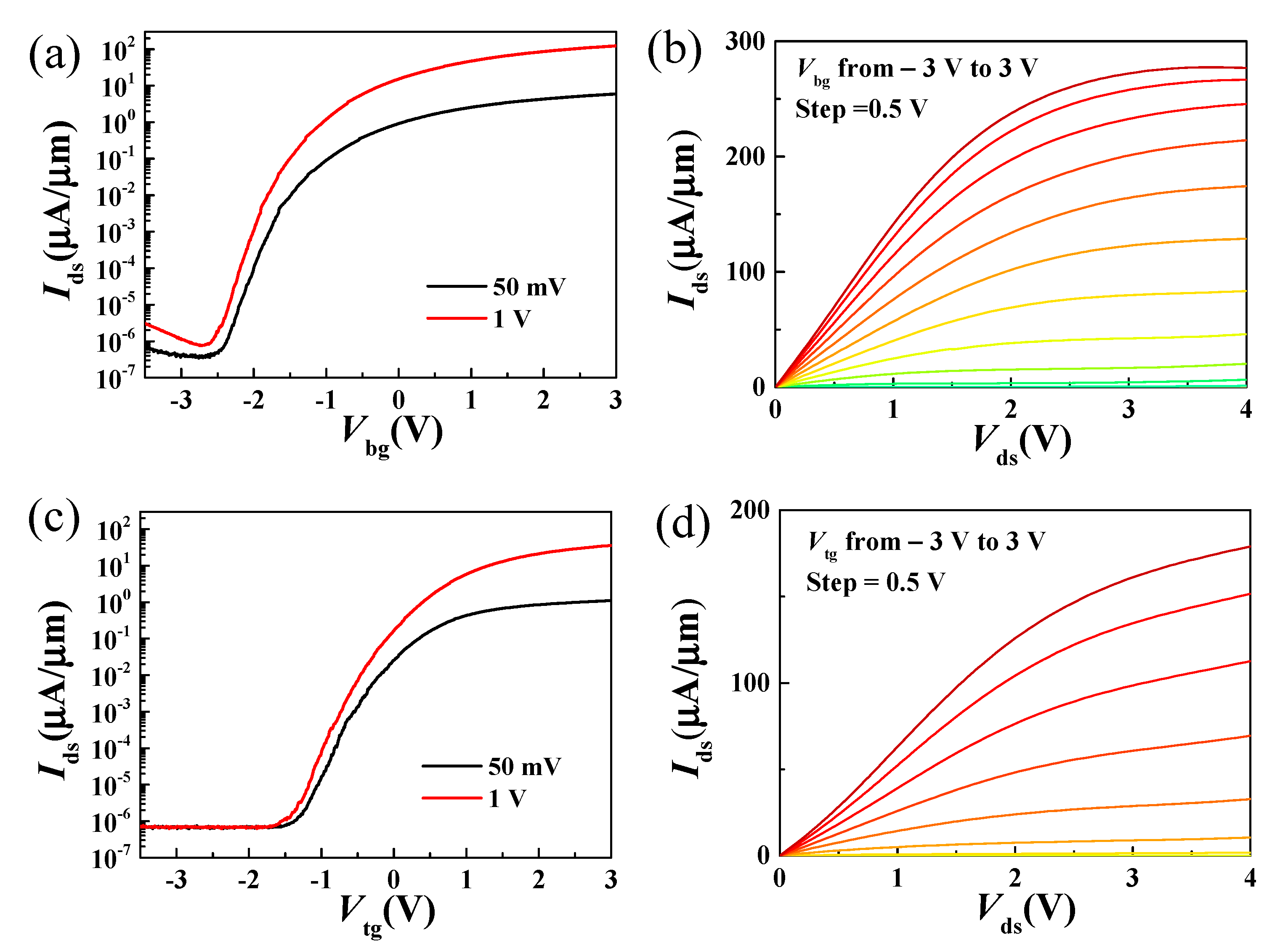
Figure 3a,c show the transfer characteristics of the dual-gate MoS2 transistor from both the back and top-gate configuration. High on/off ratios greater than 107 were achieved for both the back and top-gate modulation. Compared to graphene transistors, this superior on/off ratio is due to the larger band gap [40]. Figure 3b,d show the output characteristics under varied back and top-gate voltages. The gate voltages were varied from −3 V to 3 V with a 0.5 V step. Maximum on-current densities were observed at Vds = 4 V are 277 µA/µm and 179 µA/µm for back-gate and top-gate modulation, respectively. The achieved maximum on-current density from back-gate is about 1.6 times the magnitude of that from the top-gate. This comes from the different configuration of back-gate and top-gate devices. As shown in Figure 1d, it can be seen that the highly resistive Si substrate has global control over the entire bilayer MoS2 film. Since the channel carriers in the bilayer MoS2 films accumulate with increasing back-gate voltage, it can be assumed that the bilayer MoS2 is electrically doped under the effect of the back-gate voltage, which further leads to a reduction in the contact resistance between the source/drain (Ni/Au) and the bilayer MoS2 film. In the case of top-gate configuration, the gate can only modulate the MoS2 films underneath the gate metal [28,33,34]. In addition to the different gate structures, the different top and bottom dielectric layer may also play a critical role in determining the difference of DC measurement [19,32,41] and which need further investigation. In addition, a field-effect mobility of 15.8 cm2/Vs was obtained from back-gate measurement by using the relation μ F E = g m L W C o x V d s , where the back-gate capacitance Cox is 0.8 µF/cm2.
Figure 4a shows the transfer curves of a dual-gate MoS2 transistor with sweeping top-gate voltage at varied back-gate voltages. With the back-gate voltage increasing from 0 V to 3 V, the on-current density increases from 166 to 278 µA/μm, and the threshold voltage Vth negatively shifts from 1.1 to 0.1 V. To estimate contact resistances of dual-gate MoS2 transistors under different back-gate voltages, an interpolation method reported in previous work was adopted [35,42]. In this interpolation method, contact resistances at different Vbg were extracted by extrapolating the drain-to-source resistance vs. 1/(VtgVth), which contains the contribution from metal/MoS2 contact and the regions between top-gate and source/drain electrodes. The dependence of the contact resistances versus Vbg is shown in Figure 4b. The extracted contact resistance is 5.5 kΩ∙μm at Vbg = 0 V, and decreases to 1.99 kΩ∙μm at Vbg = 3 V. The reduced Rc and increased on-current at larger Vbg can be attributed to the increased electrostatic doping carriers of bilayer MoS2 in both the MoS2/metal contact region and channel region [28,31,33,34].

3.2. RF Characterization

The high-frequency performance of dual-gate MoS2 transistors can be evaluated by the cutoff frequency (fT) and the maximum frequency of oscillation (fmax), which can be obtained from the measured S-parameters [43,44]. The cutoff frequency is where the short-circuit current gain |h21| equals unity. The short-circuit current gain |h21| can be defined as:
h 21 = 2 S 21 ( 1 S 11 ) ( 1 + S 22 ) + S 12 S 21 .
Similarly, the maximum frequency of oscillation was found when the unilateral power gain U was unity, where the U can be defined as:
U = | S 21 S 12 1 | 2 2 K | S 21 S 12 | 2 Re ( S 21 S 12 ) ,
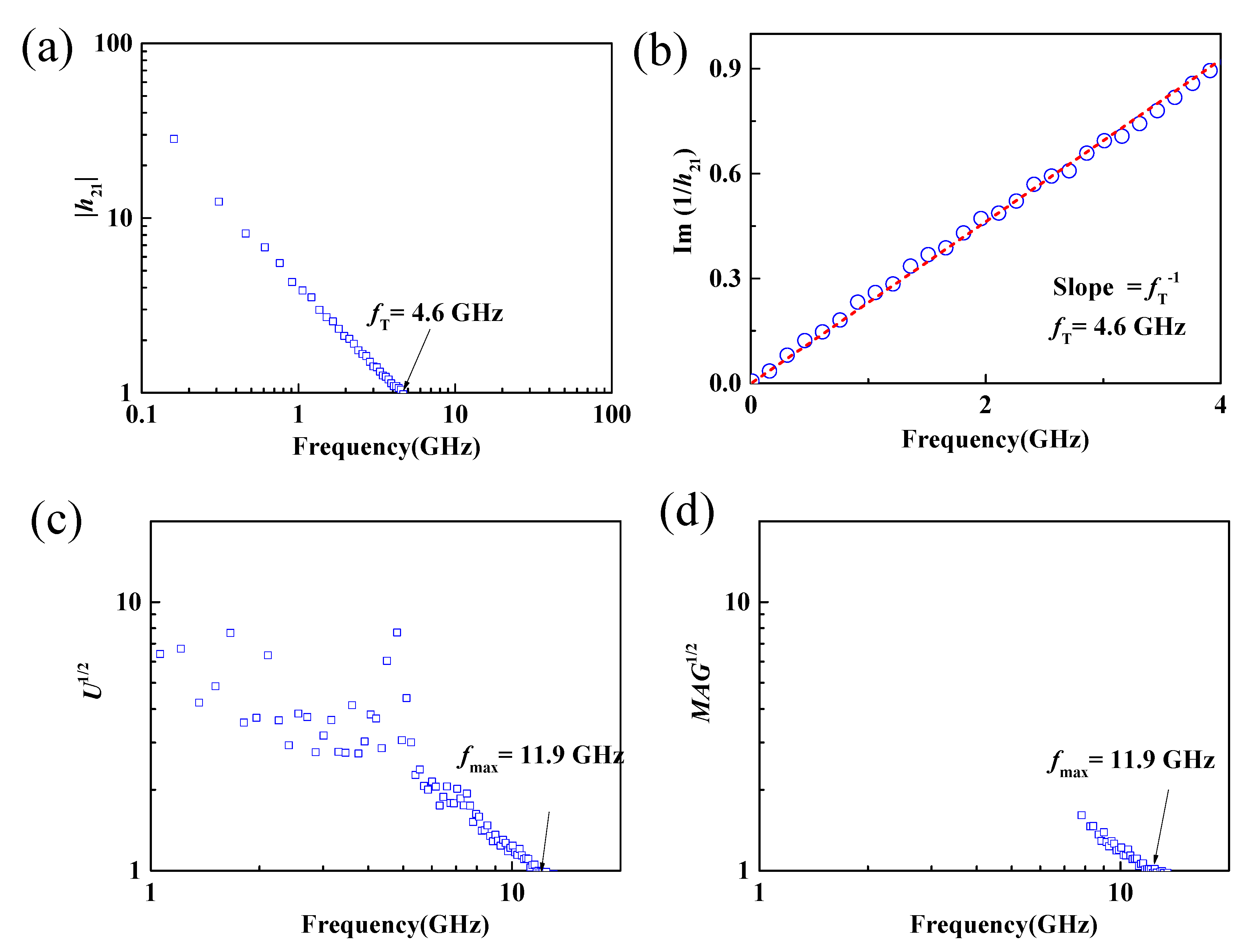
where K is the stability factor and K = 1 + | S 11 × S 22 S 12 × S 21 | 2 | S 11 | 2 | S 22 | 2 2 × | S 12 × S 21 | . On-chip microwave measurements from 100 MHz to 30 GHz of the dual-gate MoS2 RF transistors were carried out using vector network analyzers (N5225A, Agilent (Keysight), Colorado Springs, CA, USA). Before the S-parameter measurement, the on-chip measurement system was calibrated according to the short-open-load-through (SOLT) method using standard impedance calibration samples. Then S parameters of the MoS2 transistors were measured, and the short-circuit current gain and the unilateral power gain can be calculated by Equations (1) and (2). As shown in Figure 5a,c, the fT and fmax of the 190 nm MoS2 RF transistors with back-gate floating were 4.6 and 11.9 GHz, respectively. The achieved fT of 4.6 GHz and fmax of 11.9 GHz were also further verified using Gummel’s method [45] and maximum available power gain (MAG) [46], as shown in Figure 5b,d. The obtained cut-off frequency and maximum oscillation frequency were consistent with our previous reported work [16], demonstrating the potential of CVD bilayer MoS2 for large-scale high-frequency circuit applications [27,35].
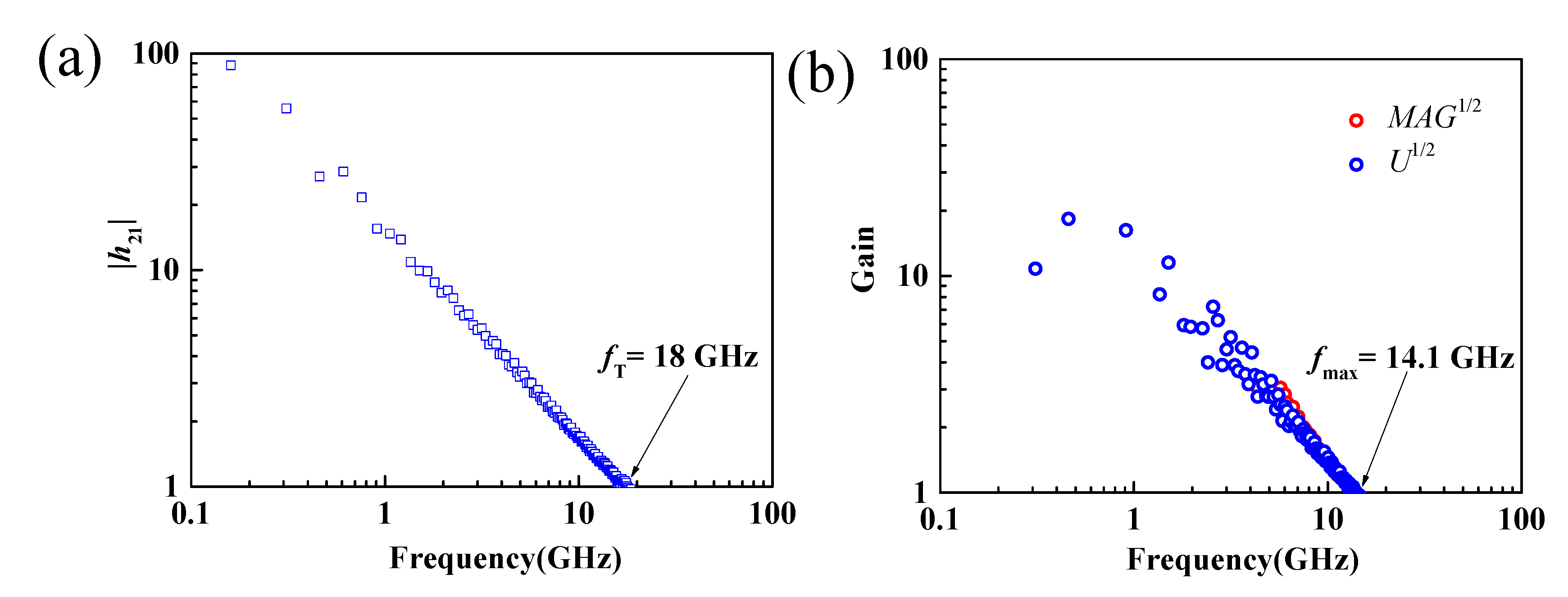
Although the implementation of the standard calibration method can move the measurement reference plane from the internal receiver of the vector network analyzer to the tip of the ground–signal–ground (GSG) probe, the parasitic capacitance, inductance, and resistance of the test electrodes also have a significant effect on the obtained S-parameters [27,47]. To eliminate the influence of the test electrodes on the measured S-parameters and to obtain the intrinsic RF performance of the MoS2 RF transistor, this work uses the standard “open” and “short” structures for de-embedding [25]. Then, the measured S-parameters were converted to Y-parameters, and the de-embedding process was performed under the following equation: Y int = [ ( Y D U T Y o p e n ) 1 ( Y s h o r t Y o p e n ) 1 ] 1 , where YDUT stands for the Y-parameter of the measured transistors. The short-circuit current gain, unilateral power gain, and maximum available power gain versus frequency after de-embedding of the MoS2 transistors with gate length of 190 nm are shown in Figure 6. Intrinsic fT and fmax of 18 and 14.1 GHz were achieved, respectively.
To improve the high-frequency performance of MoS2 RF transistors, we can derive the dependence of fT and fmax on the physical parameters of the device through the small-signal equivalent circuit model, and write them as Equations (3) and (4).
f T = g m 2 π 1 ( C g s + C g d ) [ 1 + g d s ( R s + R d ) ] + C g d g m ( R s + R d )
f max = f T 2 g d s ( R s + R d ) + 2 π f T C g R g
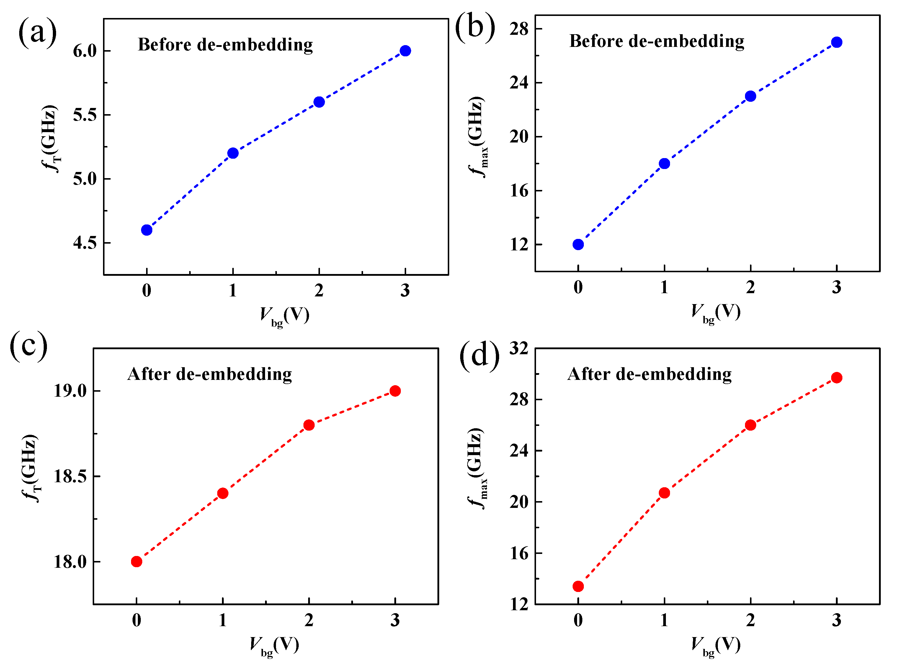
where gm is the transconductance and represents the channel current controlling capability of the gate voltage, gds is the output conductance, Cgs and Cgd is the gate-to-source and gate-to-drain capacitance, respectively. Rs, Rd and Rg are the source, drain, and gate resistances. From Equations (3) and (4), we can see that gm, gds, Rs and Rd play an important role in the high-frequency performance of RF transistors. Therefore, back-gate modulation could be an effective approach for improving the high-frequency performance of MoS2 RF transistors. Figure 7 shows the intrinsic and extrinsic cut-off frequency and maximum oscillation frequency of the device as a function of the back-gate voltage. As shown in Figure 7a,c, when the back-gate voltage changes from 0 V to 3 V, the extrinsic and intrinsic cut-off frequencies before and after de-embedding increase from 4.6 to 6 GHz and from 18 to 19 GHz, respectively, demonstrating an obtained peak fT increase as the increase of back-gate voltage. The improvement of fT can be attributed to the reduced contact resistance thus improve transconductance and on-current with increasing Vbg, as shown in Figure 4. From the intrinsic fT of 19 GHz at Vbg =3 V, a saturation velocity of 2.3 × 106 cm/s is obtained, which is comparable with previously reported works [16,25]. Similarly, when the back-gate increases from 0 to 3 V, the extrinsic and intrinsic maximum oscillation frequencies before and after de-embedding increase from 12 to 27 GHz and from 13.4 to 29.7 GHz, respectively. Because the dependence of fmax on output conductance is more sensitive, the increase of fmax with increasing Vbg is larger than fT [34]. Furthermore, a comparison between reported MoS2 RF transistors with comparable gate length [22,23,24] is listed in Table 1, below, demonstrating the advantage of dual-gate MoS2 RF transistors.

4. Conclusions

In summary, for the first time, a systematic investigation of a dual-gate MoS2 RF transistor based on CVD bilayer MoS2 was performed. Improved on-current and contact resistance performance by optimizing the back-gate voltage were demonstrated. A high on-current of 278 μA/μm and a low contact resistance of 1.99 kΩ∙µm were achieved at Vbg = 3 V. The cut-off frequency and maximum oscillation frequency can be improved by back-gate modulation. Extrinsic and intrinsic cutoff frequency of 6 and 19 GHz were demonstrated for a gate length of 190 nm at Vbg = 3 V. The intrinsic maximum oscillation frequency can become 2.1 times as high as the fmax without a back-gate bias. The results presented here indicate that tuning the back-gate voltage provides an effective way to boost fT and fmax and give an insight into the high-frequency performance of MoS2 RF transistors.

Author Contributions

Conceptualization, Q.G. and C.Z.; methodology, Q.G., P.L., Y.H., K.Y. and X.P.; validation, Q.G. and Z.Z.; formal analysis, Q.G., P.L., Z.Z. and X.P.; investigation, Q.G, Y.H.; resources, C.Z., Z.Y., J.Y., F.C. and L.L.; data curation, Q.G.; writing—original draft preparation, Q.G. and C.Z.; writing—review and editing, Q.G. and C.Z.; visualization, Q.G.; supervision, Q.G. and C.Z.; project administration, Q.G. and C.Z.; funding acquisition, Q.G., Z.Y. and C.Z. All authors have read and agreed to the published version of the manuscript.

Funding

This work was funded in part by the Guangdong Basic and Applied Basic Research Foundation (Grant No. 2019A1515110752), in part by the Youth Innovative Talent Project of Guangdong Education Department (Grant No. 2019KQNCX187), in part by the Outstanding Chinese and Foreign Youth Exchange Program of China Association for Science and Technology (CAST), 2019, in part by the Natural Science Foundation of China (Grant No 62071088), and in part by the Project for Innovation Team of Guangdong University (Grant No. 2018KCXTD033), in part by National Key R&D Program of China (Grant No. 2018YFB1801302), in part by Zhongshan Social Public Welfare Science and Technology (Grant No. 2019B2007), and in part by Research Project for Talent of UESTC Zhongshan Institute (419YKQN09).

Data Availability Statement

The data that support the findings of this study are available from the corresponding author upon reasonable request.

Conflicts of Interest

The authors declare no conflict of interest.

References

  1. Novoselov, K.S.; Geim, A.K.; Morozov, S.V.; Jiang, D.; Zhang, Y.; Dubonos, S.V.; Grigorieva, I.V.; Firsov, A.A. Electric field effect in atomically thin carbon films. Science 2004, 306, 666–669. [Google Scholar] [CrossRef] [Green Version]
  2. Schwierz, F. Graphene transistors. Nat. Nanotechnol. 2010, 5, 487–496. [Google Scholar] [CrossRef]
  3. Radisavljevic, B.; Radenovic, A.; Brivio, J.; Giacometti, V.; Kis, A. Single-layer MoS2 transistors. Nat. Nanotechnol. 2011, 6, 147–150. [Google Scholar] [CrossRef] [PubMed]
  4. Desai, S.B.; Madhvapathy, S.R.; Sachid, A.B.; Llinas, J.P.; Wang, Q.; Ahn, G.H.; Pitner, G.; Kim, M.J.; Bokor, J.; Hu, C.; et al. MoS2 transistors with 1-nanometer gate lengths. Science 2016, 354, 99–102. [Google Scholar] [CrossRef] [PubMed] [Green Version]
  5. Tombros, N.; Jozsa, C.; Popinciuc, M.; Jonkman, H.T.; Van Wees, B.J. Electronic spin transport and spin precession in single graphene layers at room temperature. Nature 2007, 448, 571–574. [Google Scholar] [CrossRef] [PubMed] [Green Version]
  6. Cho, S.; Chen, Y.-F.; Fuhrer, M.S. Gate-tunable graphene spin valve. Appl. Phys. Lett. 2007, 91, 123105. [Google Scholar] [CrossRef] [Green Version]
  7. Schedin, F.; Geim, A.K.; Morozov, S.V.; Hill, E.W.; Blake, P.; Katsnelson, M.I.; Novoselov, K. Detection of individual gas molecules adsorbed on graphene. Nat. Mater. 2007, 6, 652–655. [Google Scholar] [CrossRef] [PubMed]
  8. Ohno, Y.; Maehashi, K.; Yamashiro, Y.; Matsumoto, K. Electrolyte-Gated Graphene Field-Effect Transistors for Detecting pH and Protein Adsorption. Nano Lett. 2009, 9, 3318–3322. [Google Scholar] [CrossRef] [PubMed]
  9. Cheng, Z.; Li, Q.; Li, Z.; Zhou, Q.; Fang, Y. Suspended Graphene Sensors with Improved Signal and Reduced Noise. Nano Lett. 2010, 10, 1864–1868. [Google Scholar] [CrossRef]
  10. Cohen-Karni, T.; Qing, Q.; Li, Q.; Fang, Y.; Lieber, C.M. Graphene and Nanowire Transistors for Cellular Interfaces and Electrical Recording. Nano Lett. 2010, 10, 1098–1102. [Google Scholar] [CrossRef] [Green Version]
  11. Bunch, J.S.; Van Der Zande, A.M.; Verbridge, S.S.; Frank, I.W.; Tanenbaum, D.M.; Parpia, J.M.; Craighead, H.G.; McEuen, P.L. Electromechanical Resonators from Graphene Sheets. Science 2007, 315, 490–493. [Google Scholar] [CrossRef] [Green Version]
  12. Stoller, M.D.; Park, S.; Zhu, Y.; An, J.; Ruoff, R.S. Graphene-Based Ultracapacitors. Nano Lett. 2008, 8, 3498–3502. [Google Scholar] [CrossRef]
  13. Wang, Q.H.; Kalantar-Zadeh, K.; Kis, A.; Coleman, J.N.; Strano, M.S. Electronics and optoelectronics of two-dimensional transition metal dichalcogenides. Nat. Nanotechnol. 2012, 7, 699–712. [Google Scholar] [CrossRef]
  14. Yoon, Y.; Ganapathi, K.; Salahuddin, S. How good can monolayer MoS2 transistors be? Nano Lett. 2011, 11, 3768–3773. [Google Scholar] [CrossRef]
  15. Akinwande, D.; Petrone, N.; Hone, J. Two-dimensional flexible nanoelectronics. Nat. Commun. 2014, 5, 5678. [Google Scholar] [CrossRef] [PubMed]
  16. Gao, Q.; Zhang, Z.; Xu, X.; Song, J.; Li, X.; Wu, Y. Scalable high performance radio frequency electronics based on large domain bilayer MoS2. Nat. Commun. 2018, 9, 4778. [Google Scholar] [CrossRef] [PubMed]
  17. Lin, Z.; Liu, Y.; Halim, U.; Ding, M.; Liu, Y.; Wang, Y.; Jia, C.; Chen, P.; Duan, X.; Wang, C.; et al. Solution-processable 2D semiconductors for high-performance large-area electronics. Nat. Cell Biol. 2018, 562, 254–258. [Google Scholar] [CrossRef]
  18. Zhang, X.; Grajal, J.; Vazquez-Roy, J.L.; Radhakrishna, U.; Wang, X.; Chern, W.; Zhou, L.; Lin, Y.; Shen, P.-C.; Ji, X.; et al. Two-dimensional MoS2-enabled flexible rectenna for Wi-Fi-band wireless energy harvesting. Nature 2019, 566, 368–372. [Google Scholar] [CrossRef] [PubMed]
  19. Na, J.; Joo, M.-K.; Shin, M.; Huh, J.; Kim, J.-S.; Piao, M.; Jin, J.-E.; Jang, H.-K.; Choi, H.J.; Shim, J.H.; et al. Low-frequency noise in multilayer MoS2 field-effect transistors: the effect of high-k passivation. Nanoscale 2014, 6, 433–441. [Google Scholar] [CrossRef]
  20. Liu, N.; Baek, J.; Kim, S.M.; Hong, S.; Hong, Y.K.; Kim, Y.S.; Kim, H.-S.; Kim, S.; Park, J. Improving the Stability of High-Performance Multilayer MoS2 Field-Effect Transistors. ACS Appl. Mater. Interfaces 2017, 9, 42943–42950. [Google Scholar] [CrossRef] [PubMed] [Green Version]
  21. Chang, H.-Y.; Yogeesh, M.N.; Ghosh, R.; Rai, A.; Sanne, A.; Yang, S.; Lu, N.; Banerjee, S.K.; Akinwande, D. Large-Area Monolayer MoS2 for Flexible Low-Power RF Nanoelectronics in the GHz Regime. Adv. Mater. 2016, 28, 1818–1823. [Google Scholar] [CrossRef] [PubMed]
  22. Krasnozhon, D.; Lembke, D.; Nyffeler, C.; Leblebici, Y.; Kis, A. MoS2 Transistors Operating at Gigahertz Frequencies. Nano Lett. 2014, 14, 5905–5911. [Google Scholar] [CrossRef] [PubMed] [Green Version]
  23. Sanne, A.; Ghosh, R.; Rai, A.; Yogeesh, M.N.; Shin, S.H.; Sharma, A.; Jarvis, K.; Mathew, L.; Rao, R.; Akinwande, D.; et al. Radio Frequency Transistors and Circuits Based on CVD MoS2. Nano Lett. 2015, 15, 5039–5045. [Google Scholar] [CrossRef] [PubMed]
  24. Sanne, A.; Park, S.; Ghosh, R.; Yogeesh, M.N.; Liu, C.; Mathew, L.; Rao, R.; Akinwande, D.; Banerjee, S.K. Embedded gate CVD MoS2 microwave FETs. npj 2D Mater. Appl. 2017, 1, 26. [Google Scholar] [CrossRef] [Green Version]
  25. Cheng, R.; Jiang, S.; Chen, Y.; Liu, Y.; Weiss, N.O.; Cheng, H.-C.; Wu, H.; Huang, Y.; Duan, X. Few-layer molybdenum disulfide transistors and circuits for high-speed flexible electronics. Nat. Commun. 2014, 5, 514. [Google Scholar] [CrossRef]
  26. Krasnozhon, D.; Dutta, S.; Nyffeler, C.; Leblebici, Y.; Kis, A. High-frequency, scaled MoS2 transistors. In Proceedings of the 2015 IEEE International Electron Devices Meeting (IEDM), Washington, DC, USA, 7–9 December 2015; pp. 27.4.1–27.4.4. [Google Scholar]
  27. Gao, Q.; Zhang, C.; Yang, K.; Pan, X.; Zhang, Z.; Yang, J.; Yi, Z.; Chi, F.; Liu, L. High-Performance CVD Bilayer MoS2 Radio Frequency Transistors and Gigahertz Mixers for Flexible Nanoelectronics. Micromachines 2021, 12, 451. [Google Scholar] [CrossRef] [PubMed]
  28. Li, X.; Li, T.; Zhang, Z.; Xiong, X.; Li, S.; Wu, Y. Tunable Low-Frequency Noise in Dual-Gate MoS2 Transistors. IEEE Electron Device Lett. 2017, 39, 131–134. [Google Scholar] [CrossRef]
  29. Bolshakov, P.; Khosravi, A.; Zhao, P.; Hurley, P.K.; Hinkle, C.L.; Wallace, R.M.; Young, C.D. Dual-gate MoS2 transistors with sub-10 nm top-gate high-k dielectrics. Appl. Phys. Lett. 2018, 112, 253502. [Google Scholar] [CrossRef]
  30. Lee, G.-H.; Cui, X.; Kim, Y.D.; Arefe, G.; Zhang, X.; Lee, C.-H.; Ye, F.; Watanabe, K.; Taniguchi, T.; Kim, P.; et al. Highly Stable, Dual-Gated MoS2 Transistors Encapsulated by Hexagonal Boron Nitride with Gate-Controllable Contact, Resistance, and Threshold Voltage. ACS Nano 2015, 9, 7019–7026. [Google Scholar] [CrossRef] [PubMed]
  31. Li, X.-X.; Chen, X.-Y.; Chen, J.-X.; Zeng, G.; Li, Y.-C.; Huang, W.; Ji, Z.-G.; Zhang, D.W.; Lu, H.-L. Dual-gate MoS2 phototransistor with atomic-layer-deposited HfO2 as top-gate dielectric for ultrahigh photoresponsivity. Nanotechnology 2021, 32, 215203. [Google Scholar] [CrossRef]
  32. Li, X.; Xiong, X.; Li, T.; Li, S.; Zhang, Z.; Wu, Y. Effect of Dielectric Interface on the Performance of MoS2 transistors. ACS Appl. Mater. Interfaces 2017, 9, 44602–44608. [Google Scholar] [CrossRef]
  33. Lin, Y.-M.; Chiu, H.-Y.; Jenkins, K.A.; Farmer, D.B.; Avouris, P.; Valdes-Garcia, A. Dual-gate graphene FETs with fT of 50 GHz. IEEE Electron Device Lett. 2009, 31, 68–70. [Google Scholar] [CrossRef] [Green Version]
  34. Zhu, W.; Low, T.; Farmer, D.B.; Jenkins, K.; Ek, B.; Avouris, P. Effect of dual gate control on the alternating current performance of graphene radio frequency device. J. Appl. Phys. 2013, 114, 44307. [Google Scholar] [CrossRef]
  35. Gao, Q.; Zhang, C.; Yi, Z.; Pan, X.; Chi, F.; Liu, L.; Li, X.; Wu, Y. Improved low-frequency noise in CVD bilayer MoS2 field-effect transistors. Appl. Phys. Lett. 2021, 118, 153103. [Google Scholar] [CrossRef]
  36. Xiong, X.; Li, X.; Huang, M.; Li, T.; Gao, T.; Wu, Y. High Performance Black Phosphorus Electronic and Photonic Devices with HfLaO Dielectric. IEEE Electron Device Lett. 2017, 39, 127–130. [Google Scholar] [CrossRef]
  37. Li, S.; Tian, M.; Gao, Q.; Wang, M.; Li, T.; Hu, Q.; Li, X.; Wu, Y. Nanometre-thin indium tin oxide for advanced high-performance electronics. Nat. Mater. 2019, 18, 1091–1097. [Google Scholar] [CrossRef] [PubMed]
  38. McDonnell, S.; Brennan, B.; Azcatl, A.; Lu, N.; Dong, H.; Buie, C.; Kim, J.; Hinkle, C.L.; Kim, M.J.; Wallace, R.M. HfO2 on MoS2 by Atomic Layer Deposition: Adsorption Mechanisms and Thickness Scalability. ACS Nano 2013, 7, 10354–10361. [Google Scholar] [CrossRef]
  39. Kim, H.G.; Lee, H.-B.-R. Atomic Layer Deposition on 2D Materials. Chem. Mater. 2017, 29, 3809–3826. [Google Scholar] [CrossRef]
  40. Wang, H.; Yu, L.; Lee, Y.-H.; Shi, Y.; Hsu, A.; Chin, M.L.; Li, L.-J.; Dubey, M.; Kong, J.; Palacios, T. Integrated Circuits Based on Bilayer MoS2 Transistors. Nano Lett. 2012, 12, 4674–4680. [Google Scholar] [CrossRef] [Green Version]
  41. Joo, M.-K.; Moon, B.H.; Ji, H.; Han, G.H.; Kim, H.; Lee, G.; Lim, S.C.; Suh, D.; Lee, Y.H. Understanding Coulomb Scattering Mechanism in Monolayer MoS2 Channel in the Presence ofh-BN Buffer Layer. ACS Appl. Mater. Interfaces 2017, 9, 5006–5013. [Google Scholar] [CrossRef]
  42. Renteria, J.; Samnakay, R.; Rumyantsev, S.; Jiang, C.; Goli, P.; Shur, M.A.; Balandin, A. Low-frequency 1/f noise in MoS2 transistors: Relative contributions of the channel and contacts. Appl. Phys. Lett. 2014, 104, 153104. [Google Scholar] [CrossRef] [Green Version]
  43. Qing-Guo, G.; Meng-Chuan, T.; Si-Chao, L.; Xue-Fei, L.; Yan-Qing, W. Gigahertz frequency doubler based on millimeter-scale single-crystal graphene. Acta Phys. Sin. 2017, 66, 217305. [Google Scholar] [CrossRef]
  44. Wu, Y.; Lin, Y.-M.; Bol, A.; Jenkins, K.A.; Xia, F.; Farmer, D.B.; Zhu, Y.; Avouris, P. High-frequency, scaled graphene transistors on diamond-like carbon. Nat. Cell Biol. 2011, 472, 74–78. [Google Scholar] [CrossRef] [PubMed]
  45. Gummel, H. On the definition of the cutoff frequency fT. Proc. IEEE 1969, 57, 2159. [Google Scholar] [CrossRef]
  46. Gupta, M. Power gain in feedback amplifiers, a classic revisited. IEEE Trans. Microw. Theory Tech. 1992, 40, 864–879. [Google Scholar] [CrossRef]
  47. Li, T.; Tian, M.; Li, S.; Huang, M.; Xiong, X.; Hu, Q.; Li, S.; Li, X.; Wu, Y. Black Phosphorus Radio Frequency Electronics at Cryogenic Temperatures. Adv. Electron. Mater. 2018, 4, 1800138. [Google Scholar] [CrossRef]
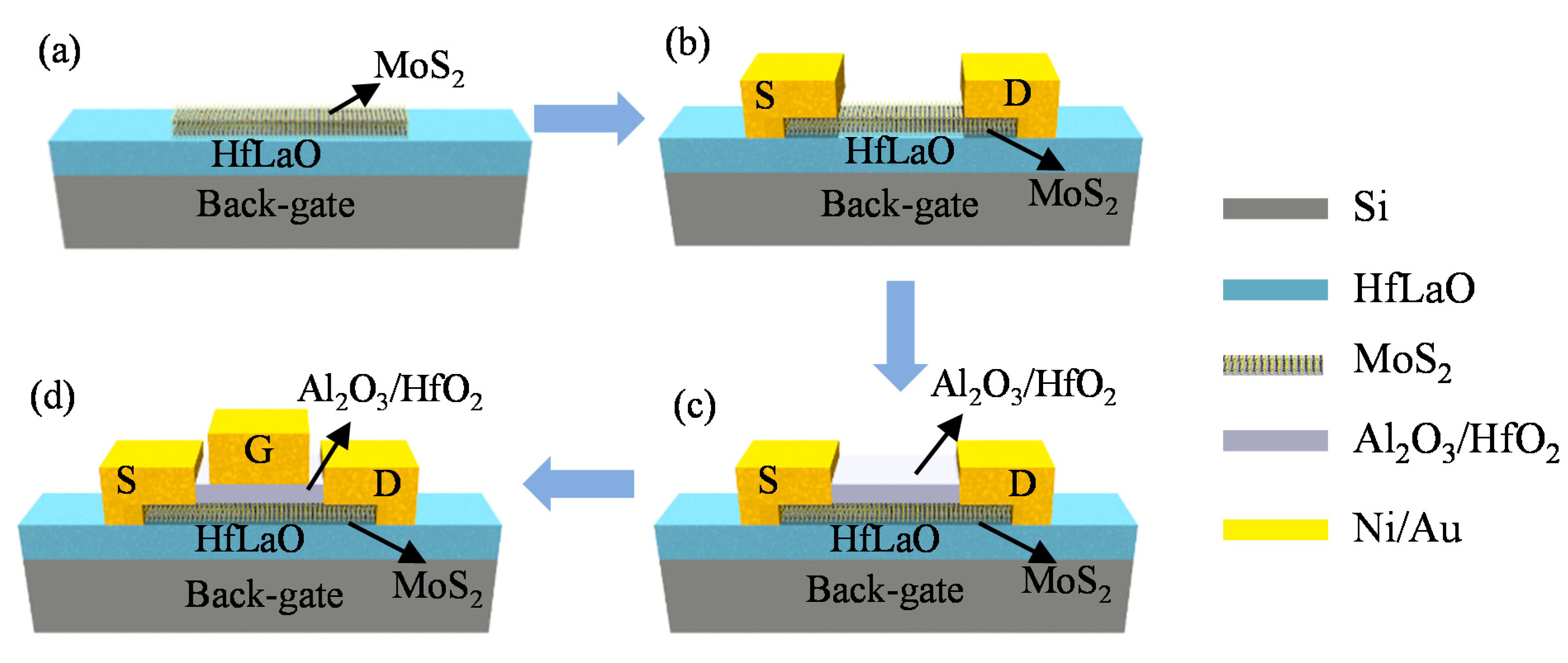
Figure 1. Process for fabricating the dual-gate MoS2 field-effect transistors. (a) Bilayer MoS2 is first transferred on HfLaO/Si substrates. (b) Source and drain contact metal deposition. (c) Top-gate dielectrics of Al2O3/HfO2 deposition. (d) Top-gate metal pattern and deposition. S: source, D: drain, G: gate.
Nanomaterials 11 01594 g001
Figure 2. (a) The transferred bilayer MoS2 on HfLaO/Si substrates. (bd) SEM images of the 190 nm MoS2 RF transistor with two-fingers structure showing excellent alignment.
Nanomaterials 11 01594 g002
Figure 3. (a,b) Transfer and output characteristics of the MoS2 dual-gate transistors from the back-gate controls. (c,d) Transfer and output characteristics of the MoS2 dual-gate transistors from the top-gate controls.
Nanomaterials 11 01594 g003
Figure 4. (a) Transfer properties of the dual-gate MoS2 transistors obtained by sweeping the top-gate voltage with varying back-gate biases at Vds = 4 V. (b) Extracted contact resistance as a function of back-gate voltage.
Nanomaterials 11 01594 g004
Figure 5. (a,b) Small-signal current gain |h21| and Im(1/h21) versus frequency. Extrinsic fT of 4.6 GHz can be extracted. (c,d) The corresponding unilateral power gain and maximum available power gain versus frequency. An extrinsic fmax of 11.9 GHz can be extracted.
Nanomaterials 11 01594 g005
Figure 6. (a) Small-signal current gain |h21| versus frequency, (b) unilateral power gain and maximum available power gain versus frequency. Intrinsic fT and fmax of 18 and 14.1 GHz could be extracted.
Nanomaterials 11 01594 g006
Figure 7. (a,b) Extrinsic fT and fmax as a function of Vbg. (c,d) Intrinsic fT and fmax as a function of Vbg.
Nanomaterials 11 01594 g007
Table 1. Comparison of reported MoS2 RF transistors with comparable gate length.
MoS2SubstrateLg (nm)fT,intrinsicfmax,intrinsicReferences
(GHz)(GHz)
ExfoliatedSiO2/Si24068.2[22]
CVD SiO2/Si2506.75.3[23]
CVD SiO2/Si1502011.4[24]
CVD HfLaO/Si1901929.7This Work
Publisher’s Note: MDPI stays neutral with regard to jurisdictional claims in published maps and institutional affiliations.