Article

Deep-Ultraviolet Transparent Conductive MWCNT/SiO2 Composite Thin Film Fabricated by UV Irradiation at Ambient Temperature onto Spin-Coated Molecular Precursor Film

1
Department of Applied Physics, School of Advanced Engineering, Kogakuin University, Tokyo 192-0015, Japan
2
Electrical Engineering and Electronics Program, Graduate School, Kogakuin University, Tokyo 192-0015, Japan
*
Author to whom correspondence should be addressed.
Nanomaterials 2021, 11(5), 1348; https://doi.org/10.3390/nano11051348
Submission received: 10 April 2021 / Revised: 1 May 2021 / Accepted: 17 May 2021 / Published: 20 May 2021
(This article belongs to the Special Issue Research of Carbon Nanomaterials and Nanocomposites)

Abstract

:
Deep-ultraviolet (DUV) light-transparent conductive composite thin films, consisting of dispersed multiwalled carbon nanotubes (MWCNTs) and SiO2 matrix composites, were fabricated on a quartz glass substrate. Transparent and well-adhered amorphous thin films, with a thickness of 220 nm, were obtained by weak ultraviolet (UV) irradiation (4 mW cm−2 at 254 nm) for more than 6 h at 20−40 °C onto the precursor films, which were obtained by spin coating with a mixed solution of MWCNT in water and Si(IV) complex in ethanol. The electrical resistivity of MWCNT/SiO2 composite thin film is 0.7 Ω·cm, and transmittance in the wavelength region from DUV to visible light is higher than 80%. The MWCNT/SiO2 composite thin film showed scratch resistance at pencil hardness of 8H. Importantly, the resistivity of the MWCNT/SiO2 composite thin film was maintained at the original level even after heat treatment at 500 °C for 1 h. It was observed that the heat treatment of the composite thin film improved durability against both aqueous solutions involving a strong acid (HCl) and a strong base (NaOH).

1. Introduction

Deep-ultraviolet (DUV) light-transparent (<300 nm) conductive films are expected to improve the performance of various optoelectronic devices, including light-emitting diodes (LEDs) and solar cells. Although conventional conductive films such as indium-doped tin oxide (ITO) and fluorine-doped tin oxide (FTO) are the most widely used, the films absorb the DUV light owing to their bandgap energy. Therefore, a new type of transparent conductive film adaptable to a wide spectral range, including DUV light, is needed. Carbon nanotubes (CNTs) are of great interest for use as composites owing to their very high strength, electronic conductivity, and flexibility [1]. CNTs/inorganic composites have attracted interest in recent decades owing to their optical, mechanical, electrical, and thermal properties [2,3]. However, the poor adhesion of CNTs onto the substrate becomes a problem during usage. As a matrix of inorganic composites with CNTs, SiO2 is an ideal material because of its availability, chemical and thermal stability, and transparency to ultraviolet (UV) radiation. Accordingly, many researchers have reported nanocomposite powders of multiwalled carbon nanotubes (MWCNTs) with SiO2 powders using various techniques such as the sol–gel, electrophoretic deposition, and direct mixing of MWCNTs and SiO2 powders [2,4,5]. However, there are very few reports of MWCNT/SiO2 composite thin films fabricated by solution processing, because it is generally difficult to obtain uniformly dispersed MWCNTs with high content in the film due to their easy aggregation by strong van der Waals forces [3]. This suggests that a stable SiO2 precursor solution exhibiting high miscibility with MWCNT is required.
The molecular precursor method (MPM) is a wet chemical process that was developed by our research group for fabricating thin films of various metals, metal oxides, and phosphate compounds [6]. This method is based on the design of a metal complex, which has many advantages, such as excellent stability, homogeneity, and miscibility. Recently, the fabrication of crystallized Cu2O and amorphous titania thin films through UV irradiation of a precursor film was achieved by our research group [7,8]. The complexes used in the precursor films were successfully converted into functional thin films by irradiating UV light from a germicidal lamp at 30−40 °C.
In this study, we prepared a novel MWCNT/SiO2 precursor solution and fabricated a deep-ultraviolet transparent conductive MWCNT/SiO2 thin film well-adhered onto a quartz glass substrate by UV irradiation of the molecular precursor film. The electrical resistivity of the obtained MWCNT/SiO2 composite thin film was 0.7 Ω·cm. The composite thin film exhibited good thermal stability and antioxidation performance at 500 °C under atmospheric conditions. In addition, we reported the chemical stability of the UV-irradiated composite thin films and the effects of heat treatment on their durability against strong acids and bases in aqueous solutions.

2. Materials and Methods

2.1. Materials

Tetraethyl orthosilicate (TEOS) was purchased from Kanto Chemical Co., Inc. (Tokyo, Japan). Oxalic acid and sodium hydroxide (NaOH) were purchased from FUJIFILM Wako Pure Chemical Corporation (Miyazaki, Japan). Hydrochloric acid (HCl), 2-propanol, and 28% aqueous ammonia solution were purchased from Taisei Chemical Co., Ltd. (Tokyo, Japan). MWCNTs (2 wt %) dispersed in water (MWNT-INK, SCNT) were purchased from Meijo Nano Carbon Co., Ltd. (Aichi, Japan). Deionized water was purchased from Kyoei Pharmaceutical Co., Ltd. (Chiba, Japan). Ethanol (EtOH) was purchased from Ueno Chemical Industries, Ltd. (Tokyo, Japan) and dried on 4A molecular sieves prior to use. The other materials were used as received without further purification. Polished quartz glass was purchased from Akishima Glass Co., Ltd. (Tokyo, Japan). The quartz glass substrates (20 × 20 × 1.5 mm3) were prepared and cleaned using 2-propanol with an ultrasonic bath to remove organic molecules from the surfaces, followed by thorough rinsing with deionized water. The substrates were subsequently dried in an oven at 70 °C.

2.2. Preparation of SiO2 Precursor Solution (SSilica)

The SiO2 precursor solution (SSilica) was prepared by the reaction of 1.3 g of TEOS with 1.1 g of oxalic acid in 10 g of ethanol under reflux for 1 h. The concentration of Si4+ ions was 0.5 mmol g−1.

2.3. Preparation of MWCNT/SiO2 Composite Precursor Solution (SCOMP)

The MWCNT/SiO2 composite precursor solution (SCOMP) was prepared by mixing 0.1 g of SSilica, 0.3 g of MWNTs-INK, and 5.7 g of H2O at room temperature. Afterward, it was stirred for 1 h.

2.4. Fabrication of MWCNT/SiO2 Composite Thin Films (FCOMP) by UV-Light Irradiation and Heat Treatment (F’COMP)

The composite thin film was obtained as a three-layer film, as follows: 100 μL of SCOMP was dropped on a quartz glass substrate of dimensions 20 × 20 mm2 using a micropipette, and subsequently spin-coated in double-step mode (first = 500 rpm for 5 s and second = 2000 rpm for 30 s). The precursor film was obtained by preheating the spin-coated film in a drying oven at 70 °C for 10 min. The first layer was formed by irradiating UV light at 254 nm (with a corresponding intensity of 4 mW cm−2) for 6 h onto the precursor film under a relative humidity range of 20−40% on a clean bench. The substrate surface temperature during UV irradiation (measured using a digital thermocouple) was in a range of 20−40 °C. The second layer was formed on the first layer by repeating the procedure used for the formation of the first layer. Thereafter, a well-adhered three-layer film on the quartz glass substrate was obtained by spin coating an additional layer of SSilica on the second layer, according to the procedure used for the first and second layers. The resultant thin film was denoted as FCOMP. F’COMP was obtained by heat treating FCOMP at 500 °C for 1 h in air using an electric furnace.
As a reference, a CNT single-layer thin film (FCNT) was formed by spin coating MWNT-INK and preheating using the abovementioned procedure. The F’CNT was obtained by heat treating the FCNT at 500 °C for 1 h in air using an electric furnace.

2.5. Optical Characterization of Solutions and Thin Films

The absorption spectra of the SSilica and TEOS solutions, whose Si4+ ion concentrations were adjusted to 0.5 mmol g−1 by dilution with ethanol, were measured in the wavelength region of 200–600 nm using a UV-1900i spectrophotometer (Shimadzu, Kyoto, Japan) in the double-beam mode. Ethanol was used as a reference. The transmittance spectra of FCOMP and FCNT were measured in the range of 200–1100 nm in double-beam mode. A quartz glass substrate was used as a reference for the measurements.

2.6. Structural Characterization of Thin Films

The X-ray diffraction (XRD) patterns of FCOMP and FCNT were measured using an X-ray diffractometer (SMART LAB, Rigaku, Tokyo, Japan) with Cu-Kα rays generated at 45 kV and 200 mA. Parallel beam optics with an incident angle of 0.3° in the 2θ range of 10–80° and scanning at a 0.05° step width and speed of 5° min−1 were used (Supplementary Materials Figure S1). The Raman spectra of FCOMP, F’COMP, FCNT, and F’CNT were measured using a Raman microspectrometer (LaBRAM HR800, Horiba Ltd., Kyoto, Japan) with a charge-coupled device detector. An Nd: YAG laser (532 nm) was used as the excitation source, with an intensity of 13 mW and an exposure time of 180 s. The spectra were measured in back-scattering geometry, and the spot diameter of the laser light was 1 μm. Spectra in the range of 900–2100 cm−1 were obtained by exposing the sample thin films to the laser beam for 30 min. Before the thin-film measurements, a silicon reference sample with a Raman peak at 520.64 cm−1 was used for the calibration of the wavelength. The Raman peaks of FCOMP, F’COMP, FCNT, and F’CNT were quantitatively analyzed by using OriginPro2018b (OriginLab Corporation, Northampton, MA, USA), in order to evaluate the structural changes of MWCNT molecules by the heat-treatment. The peaks in the range of 900−1900 cm−1 were deconvoluted by a nonlinear least-square method with the use of Lorentz function. The peak fitting converged with the χ2 tolerance value of 1 × 10⁻⁹. The deconvoluted peaks are shown in the Supplementary Materials Figure S2.

2.7. Surface Morphologies, Film Thicknesses, and Pencil Hardnesses of FCOMP and FCNT

The surface morphologies of FCOMP and FCNT were observed by field-emission scanning electron microscopy (FE-SEM) using a JSM-6701F microscope (JEOL Ltd., Tokyo, Japan) at an accelerating voltage of 5 kV. The average grain size of each thin film was calculated from 10 randomly selected grains.
The thicknesses of the thin films were measured using a stylus profilometer (DEKTAK-3, Sloan, CA, USA). For sample preparation, a portion of each precursor film was removed by ethanol to expose the substrate. The level differences at five positions between the substrate and the resultant thin film were measured for each sample. The film thickness was calculated as the average value, excluding the highest and lowest values.
The pencil hardness was evaluated according to the Japanese Industrial Standard (JIS) K5400 by a pencil scratch test using an MJ-PHT pencil hardness meter (Sato Shouji Inc., Kanagawa, Japan) with a 0.75 kg load. The film was scratched using a pencil (UNI, Mitsubishi Pencil Co., Ltd., Tokyo, Japan) with various hardness values standardized in the hardening order from 6B to 9H.

2.8. Electrical Resistivities of FCOMP, F’COMP, FCNT, and F’CNT

The electrical resistivities of the thin films were measured using the four-probe method involving two multimeters (VOAC7512, Iwatsu and Model Multimeter, Keithley, Fort Worth, TX, USA) and a regulated DC power supply (Model PAB 32-1.2, Kikusui Electronics Corp., Yokohama, Japan) at 25 °C. Four gold-plated tungsten probes (FELL type, K&S, Washington, DC, USA) were placed at intervals of 1 mm, and a load of 0.1 kg was applied.

2.9. Chemical Stabilities of FCOMP and F’COMP against Acids and Bases in Water

Three samples of FCOMP were prepared and each sample was immersed in a 10% aqueous solution of hydrochloric acid (HCl, strong acid; sa), ammonia (NH3, weak base; wb), and sodium hydroxide (NaOH, strong base; sb) for 1 h at 20 °C. The immersed samples in each solution were rinsed with water and dried at 70 °C for 10 min, and denoted as FCOMP-sa, FCOMP-wb, and FCOMP-sb, respectively. Additionally, three samples of F’COMP were prepared and treated in procedures identical to those used for FCOMP. The obtained samples were denoted as F’COMP-sa, F’COMP-wb, and F’COMP-sb, respectively. The film thicknesses, electrical resistivities, and hardnesses of these films were measured to evaluate their chemical stabilities.

3. Results and Discussion

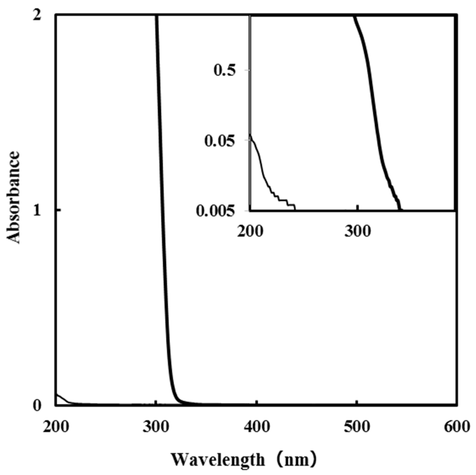
3.1. Absorption Spectra of SSilica

The absorption spectra of the SSilica and TEOS solutions of 0.5 mmol g−1 in ethanol are shown in Figure 1. The absorption of SSilica observed in the UV region is stronger than that of the TEOS solution, although the concentrations of Si4+ ions in both solutions are equal.
Some researchers have reported the tris (oxalato) complex of Si4+ ions [9,10]. The strong absorption in the UV-light region of SSilica indicates that identical coordination bonds are formed by the reaction of TEOS and oxalic acid in this precursor solution. To obtain high solubility in ethanol by assuming a neutral Si complex, the molar amount of the added oxalic acid was two times higher than that of the Si4+ ion. As a result, a precursor solution with excellent miscibility and coatability could be prepared.
We previously reported the fabrication of amorphous titania thin films by applying a low-power germicidal lamp with an irradiation peak at 254 nm, for 4 h under a relative humidity range of 40–60% at 30–40 °C [8], onto the precursor film comprising the titanium complex of an oxalato ligand. The oxalato ligand can be removed stepwise by UV irradiation. This is because of the strong absorption which can be attributed to the charge transfer (CT) transition band in the UV-light region, as shown in Figure 1.

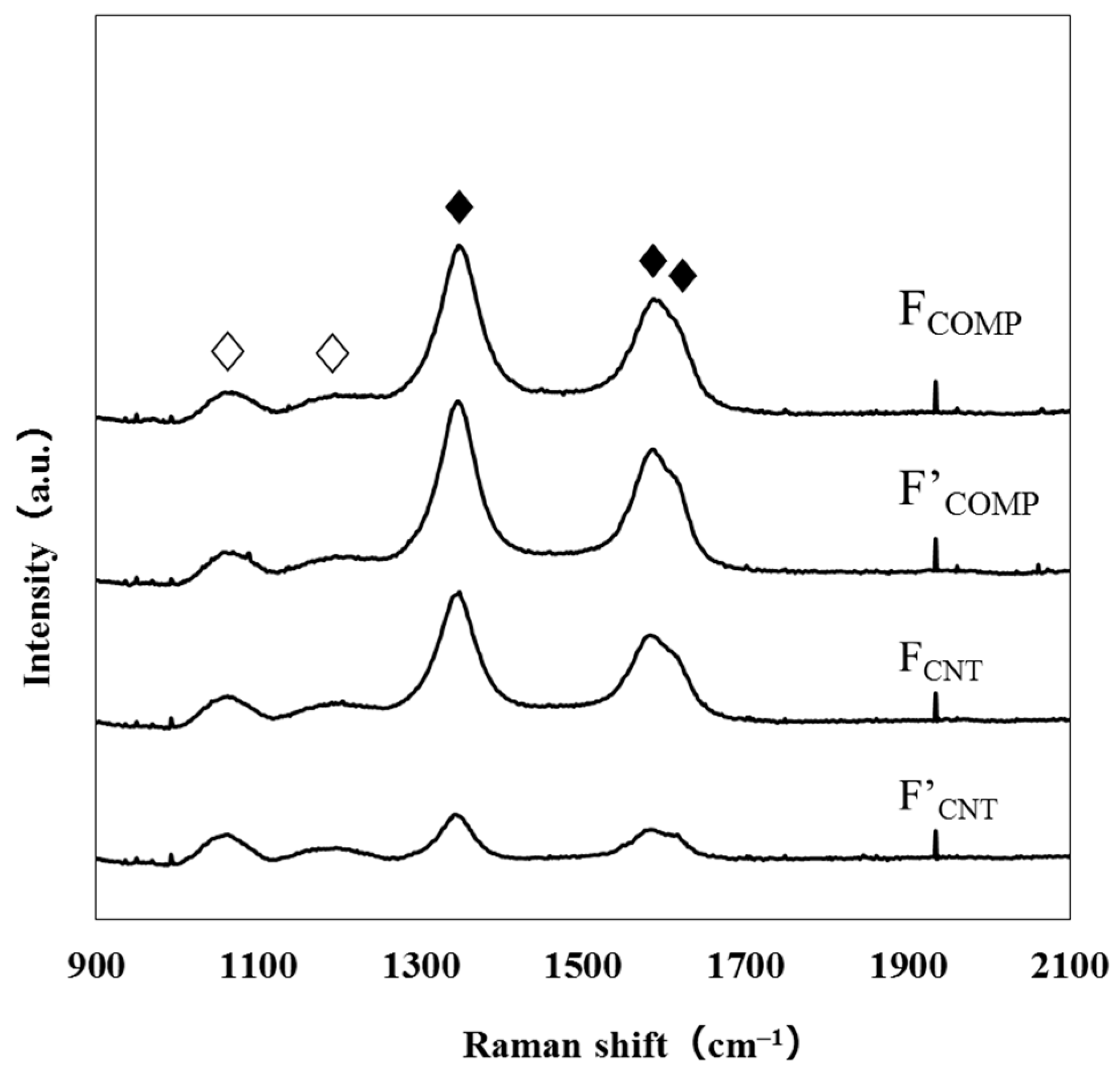
3.2. Structural Characterization of FCOMP and F’COMP

Several researchers reported that the periodically aggregated MWCNTs indicate XRD peaks at 2θ = 26 and 43°, assignable to the (002) and (100) phases [11,12,13]. However, XRD patterns of FCOMP and FCNT show no peak, indicating the randomly arranged MWCNTs in amorphous SiO2 matrix (Supplementary Materials Figure S1). Figure 2 shows the Raman spectra of FCOMP, F’COMP, FCNT, and F’CNT. The two peaks at 1060 and 1190 cm−1 are the transverse optic (TO) and the longitudinal optic (LO) ω4 modes of SiO2, respectively [14]. The three peaks at 1350, 1590, and 1620 cm−1 can be ascribed to the D, G, and D’ bands of CNT [15]. Totally five peaks could be successfully deconvoluted (Suppplementary Figure S2). Each peak area of the deconvoluted peaks was normalized with that of the TO band of SiO2. As a result, the (D + D’)/TO and G/TO ratios of FCNT decreased by 71% and 62%, respectively, by the heat treatment to produce F’CNT, indicating the significant loss of the MWCNT molecules. On the other hand, those ratios of FCOMP decreased by only 12% and 4%, respectively. These results clearly indicate that the SiO2 matrix plays an important role to prevent the co-present MWCNT molecules from oxidation. However, it is acceptable that the slightly increased resistivity of F’COMP as compared to FCOMP is owing to the decrease of MWCNT molecules in the film (see Section 3.4, Supplementary Materials Table S1). It was additionally revealed that the defective parts of CNTs are more likely to be lost by the heat treatment at 500 °C for 1 h, than the graphite parts.

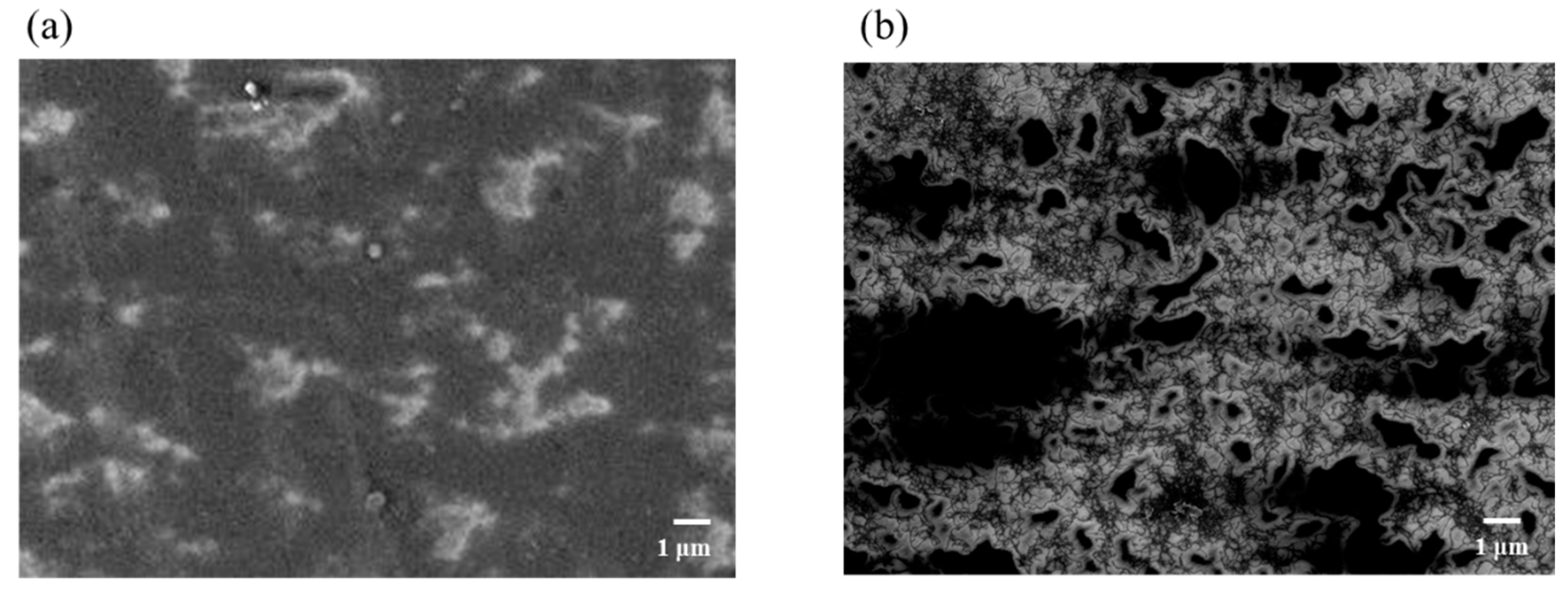
3.3. Surface Morphologies of FCOMP and FCNT

Figure 3 shows the surface morphologies of FCOMP and FCNT, which are observed using FE-SEM. The surface morphology of FCOMP suggests the dispersion of MWCNT molecules in the SiO2 matrix, though the corresponding molecules are clearly observed in that of FCNT. The SiO2 precursor solution was highly miscible with the dispersed solution of MWCNT. Therefore, the MWCNT molecules did not aggregate by van der Waals forces in the mixed solution with SSilica, and a homogeneous film could be obtained.

3.4. Film Thicknesses, Pencil Hardnesses, and Electrical Resistivities of FCOMP and F’COMP, and Their Chemical Stabilities

Table 1 summarizes the film thicknesses, electrical resistivities, and pencil hardnesses of the obtained three-layer composite thin films. Before coating with the SiO2 thin film, the one- and two-layer thin films were softer than the pencil hardness of 6B. However, the thin film FCOMP became harder than 8H after it was coated with SiO2 as the third layer, which fully covered the composite film, as shown in the SEM image (Figure 3a). It is important to note that the resistivity of the heat-treated F’COMP can be maintained at the original level after heat treatment at 500 °C under atmospheric conditions for 1 h, and the decrease in film thickness was within 5%.
Conversely, the film thickness of the FCNT could not be measured using the stylus profilometer, because the MWCNT film was easily peeled off the substrate by tracing the surface with the stylus. For this reason, the electrical conductivity of FCNT could not be determined using the four-probe method.
To examine the chemical stability of the obtained thin films, the FCOMP was immersed separately in two 10% aqueous solutions of a strong acid (HCl) and a strong base (NaOH) for 1 h at 20 °C. As a result, the film thickness of the obtained FCOMP-sa after immersion in the 10% HCl solution decreased by approximately 18%, which is larger than that of the F’COMP obtained by heat treatment at 500 °C for 1 h. However, the electrical resistivity of FCOMP-sa was almost identical to that of F’COMP. The obtained FCOMP was peeled off by immersion in the 10% NaOH solution. Therefore, a 10% aqueous ammonia solution was used to test the durability of the FCOMP against a weak base. The obtained thin film FCOMP-wb exhibited an identical film thickness and electrical resistivity as FCOMP-sa, although the pencil hardness was inferior to those of the other treated films. All the film thickness of composite thin films decreased in almost identical levels, 18−19%, with the chemical treatment. It can be assumed that the dangling bonds of incomplete Si–O network on the surface of the composite thin films after UV irradiation exist and can react with acids and bases. As mentioned above, the slight shrinkage of the film thickness by the heat treatment of FCOMP occurred. It is thus clear that the heat treatment in air contributed to form more rigid Si−O bond network. The chemical stability of F’COMP against basic aqueous solutions became to be higher than that of FCOMP, because the dangling bonds in Si–O network are presumed to be reactive highly with the employed bases. It is very important to note that the heat-treated F’COMP is highly robust in both aqueous solutions involving strong acids (HCl) and bases (NaOH), producing F’COMP-sa and F’COMP-sb, respectively.

3.5. Optical Properties of the FCOMP and FCNT

Figure 4 shows the transmittance spectra of FCOMP and FCNT. The FCOMP exhibited more than 80% transmittance in the wavelength region from DUV to visible light. The characteristic absorption at 273 nm (4.5 eV) is due to the π-plasmon of carbon nanotubes. The absorption peaks are related to the polarization dependence and the optical properties of graphite [16]. Lehman et al. reported that MWCNTs exist as aggregates and bundles in suspension, with no special features in the UV and visible spectra. If the sonication energy is sufficient to overcome the van der Waals attraction between adjacent tubes in the solution, the entanglement is undone and dispersibility increases, which is associated with more obvious spectral characteristics, such as the appearance of π-plasmon peaks [17]. The plasmon peak of FCOMP is stronger than that of FCNT. This indicates that the MWCNT molecules in the FCOMP distribute more homogeneously than those in the FCNT. It is consistent that the FE-SEM images demonstrate the homogeneous distribution of MWCNT molecules, which leads to a low electrical resistivity of the composite film.

4. Conclusions

A SiO2 precursor solution with no precipitation was prepared by forming the Si4+ complex of oxalic acid in the molar ratio of 1:2 in ethanol. The SiO2 precursor solution was highly miscible with an aqueous solution dispersed of MWCNTs. The mixed solution was adequate to form a homogenous precursor film, which can be easily converted to a MWCNT/SiO2 composite thin film by irradiating UV light from a germicidal lamp via a spin-coating process on a quartz glass substrate. Thus, the MPM used in the present study is an effective and facile method for the low-temperature fabrication of conductive thin films with transparency in the wavelength region from DUV to visible light. This unprecedented thermally and chemically robust composite thin film may improve the performance of various optoelectronic devices, including LEDs and solar cells.

Supplementary Materials

The following are available online at https://www.mdpi.com/article/10.3390/nano11051348/s1., Figure S1 XRD patterns of the obtained thin films, (a) FCOMP, (b) F’COMP, (c) FCNT, and (d) F’CNT., Figure S2: Deconvoluted Raman peaks of the obtained thin films, (a) FCOMP, (b) F’COMP, (c) FCNT and (d) F’CNT, along with each original spectrum in the range of 900–1900 cm–1. The thick line indicates the observed spectra, while five lines, (- - -), (— — —), (• • •), (—), and (— • —) indicate the theoretically fitted curves assignable the TO, LO, D, G, and D’ bands, respectively. All the calculated curves completely overlapped the corresponding observed curves., Table S1; The (D+D’)/TO and G/TO peak area ratios calculated from the Raman spectra of the obtained thin films, along with the decreasing levels of the ratios with the heat treatment are shown. The peak area was normalized with the TO band of SiO2.

Author Contributions

Conceptualization, H.N. and M.S.; methodology, M.S.; validation, H.N. and M.S.; formal analysis, H.N.; investigation, H.N. and N.O.; resources, M.S.; data curation, N.O.; writing—original draft preparation, H.N.; writing—review and editing, M.S.; visualization, N.O.; supervision, M.S.; project administration, M.S.; funding acquisition, H.N. and M.S. All authors have read and agreed to the published version of the manuscript.

Funding

This work was funded by the Japan Society for the Promotion of Science (JSPS) KAKENHI Grant Number JP20K05270, and the Japan Science and Technology Agency (JST)-Mirai Program, Grant Number JPMJMI18DA.

Data Availability Statement

Not applicable.

Acknowledgments

This study was supported partly by the International Research Project of Kogakuin University in collaboration with the National University of Singapore. The authors would like to thank Takeyoshi Onuma for his cooperation during the Raman measurements.

Conflicts of Interest

The authors declare no conflict of interest.

References

  1. Iijima, S. Helical microtubules of graphitic carbon. Nature 1991, 354, 56–58. [Google Scholar] [CrossRef]
  2. Guo, S.; Sivakumar, R.; Kitazawa, H.; Kagawa, Y. Electrical properties of silica-based nanocomposites with multiwall carbon nanotubes. J. Am. Ceram. Soc. 2007, 90, 1667–1670. [Google Scholar] [CrossRef]
  3. He, J.; Chen, J.; Shi, L.; Li, Q.; Lu, W.; Qu, S.; Qiu, W.; Zhou, G. Fabrication of thermally robust carbon nanotube (CNT)/SiO2 composite films and their high-temperature mechanical properties. Carbon N. Y. 2019, 147, 236–241. [Google Scholar] [CrossRef]
  4. Seeger, T.; Köhler, T.; Frauenheim, T.; Grobert, N.; Terrones, M.; Seifert, G. Nanotube composites: Novel SiO2 coated carbon nanotubes. Chem. Commun. 2002, 2, 34–35. [Google Scholar] [CrossRef] [PubMed]
  5. Ning, J.; Zhang, J.; Pan, Y.; Guo, J. Fabrication and mechanical properties of SiO2 matrix composites reinforced by carbon nanotube. Mater. Sci. Eng. A 2003, 357, 392–396. [Google Scholar] [CrossRef]
  6. Nagai, H.; Sato, M. The Science of Molecular Precursor Method. Adv. Coat. Mater. 2018, 1–27. [Google Scholar] [CrossRef]
  7. Wu, H.-J.; Tomiyama, N.; Nagai, H.; Sato, M. Fabrication of a p-type Cu2O thin-film via UV-irradiation of a patternable molecular-precursor film containing Cu(II) complexes. J. Cryst. Growth 2019, 509, 112–117. [Google Scholar] [CrossRef]
  8. Wu, H.-J.; Tanabe, K.; Nagai, H.; Sato, M. Photo-Induced Super-hydrophilic Thin Films on Quartz Glass by UV Irradiation of Precursor Films Involving a Ti(IV) Complex at Room Temperature. Materials 2019, 12, 348. [Google Scholar] [CrossRef] [Green Version]
  9. Balkus, K.J.; Gabrielova, I.S.; Bott, S.G. Tris(oxalato) Complexes of Silicon as Precursors to Porous Silicate Materials: Synthesis and Structure. Inorg. Chem. 1995, 34, 5776–5780. [Google Scholar] [CrossRef]
  10. Seiler, O.; Burschka, C.; Penka, M.; Tacke, R. Dianionic tris[oxalato(2-)]silicate and tris[oxalato(2-)]germanate complexes: Synthesis, properties, and structural characterization in the solid state and in solution. Z. Anorg. Allg. Chem. 2002, 628, 2427–2434. [Google Scholar] [CrossRef]
  11. Zhao, J.; Zhang, J.; Wang, L.; Lyu, S.; Ye, W.; Xu, B.B.; Qiu, H.; Chen, L.; Gu, J. Fabrication and investigation on ternary heterogeneous MWCNT@TiO2-C fillers and their silicone rubber wave-absorbing composites. Compos. Part A Appl. Sci. Manuf. 2020, 129, 105714. [Google Scholar] [CrossRef]
  12. Kocyigit, A.; Orak, I.; Karteri, İ.; Uruş, S. The structural analysis of MWCNT-SiO2 and electrical properties on device application. Curr. Appl. Phys. 2017, 17, 1215–1222. [Google Scholar] [CrossRef]
  13. Díaz-Corona, N.; Martínez-Juárez, J.; Pérez-Luna, J.G.; Hernández-de la Luz, A.D.; Rabanal, M.E.; Robles-Águila, M.J. Structural, optical and electrical behavior of zinc oxide/MWCNT composite thin films. Opt. Quantum Electron. 2019, 51, 1–11. [Google Scholar] [CrossRef]
  14. Galeener, F.L. Band limits and the vibrational spectra of tetrahedral glasses. Phys. Rev. B 1979, 19, 4292–4297. [Google Scholar] [CrossRef]
  15. Bokobza, L.; Bruneel, J.-L.; Couzi, M. Raman Spectra of Carbon-Based Materials (from Graphite to Carbon Black) and of Some Silicone Composites. C J. Carbon Res. 2015, 1, 77–94. [Google Scholar] [CrossRef] [Green Version]
  16. Murakami, Y.; Einarsson, E.; Edamura, T.; Maruyama, S. Polarization dependent optical absorption properties of single-walled carbon nanotubes and methodology for the evaluation of their morphology. Carbon N. Y. 2005, 43, 2664–2676. [Google Scholar] [CrossRef]
  17. Lehman, J.H.; Terrones, M.; Mansfield, E.; Hurst, K.E.; Meunier, V. Evaluating the characteristics of multiwall carbon nanotubes. Carbon N. Y. 2011, 49, 2581–2602. [Google Scholar] [CrossRef]
Figure 1. Absorption spectra of the SSilica (bold line) and Tetraethyl orthosilicate (TEOS) solutions in ethanol (thin line). The concentrations (0.5 mmol g−1) of Si4+ ions are identical to each other. The inset plotted the absorbance on a semi-log scale.
Nanomaterials 11 01348 g001
Figure 2. Raman spectra of the resultant thin films. The peaks attributable to the vibration modes for CNT and SiO2 are represented by ♦ and ♢, respectively.
Nanomaterials 11 01348 g002
Figure 3. FE-SEM images of (a) FCOMP (b) FCNT.
Nanomaterials 11 01348 g003
Figure 4. Transmittance spectra of FCOMP (bold line) and FCNT (thin line).
Nanomaterials 11 01348 g004
Table 1. Film thicknesses, electrical resistivities, and pencil hardnesses of FCOMP and F’COMP fabricated onto the quartz glass substrate, along with those of the chemically treated thin films FCOMP-sa, F’COMP-sa, FCOMP-wb, F’COMP-wb, and F’COMP-sb.
FilmFilm ThicknessElectrical ResistivityPencil Hardness
nmΩ·cm
FCOMP2200.7 ± 0.18H
F’COMP2100.9 ± 0.18H
FCOMP-sa1800.7 ± 0.18H
F’COMP-sa1800.9 ± 0.18H
FCOMP-wb1800.8 ± 0.14H
F’COMP-wb1800.9 ± 0.18H
F’COMP-sb1700.8 ± 0.18H
Publisher’s Note: MDPI stays neutral with regard to jurisdictional claims in published maps and institutional affiliations.

