
New Sustainable, Scalable and One-Step Synthesis of Iron Oxide Nanoparticles by Ion Exchange Process

 , , and
Abstract
1. Introduction
2. Materials and Methods
2.1. Materials
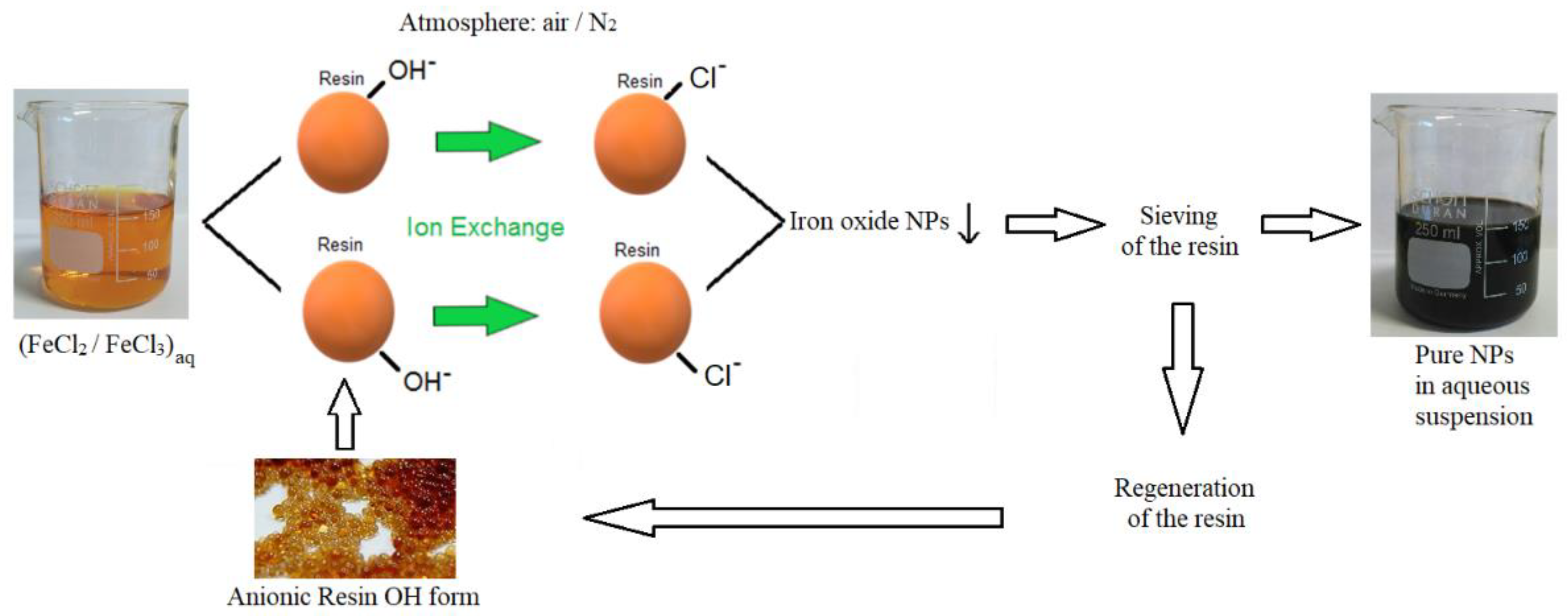
2.2. Synthesis of Iron Oxide or Hydroxide Nanoparticles by Ion Exchange Method
2.3. Production of Hematite and Maghemite NPs by Means of Calcination
2.4. Characterization Analyses
3. Results and Discussion
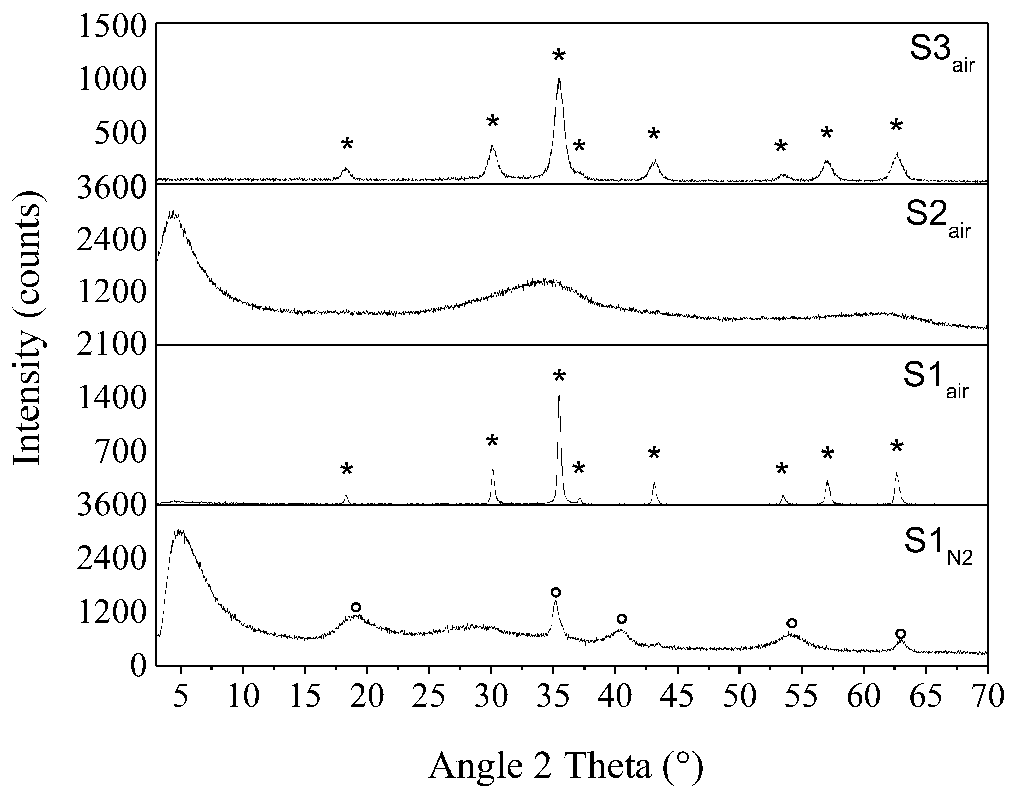
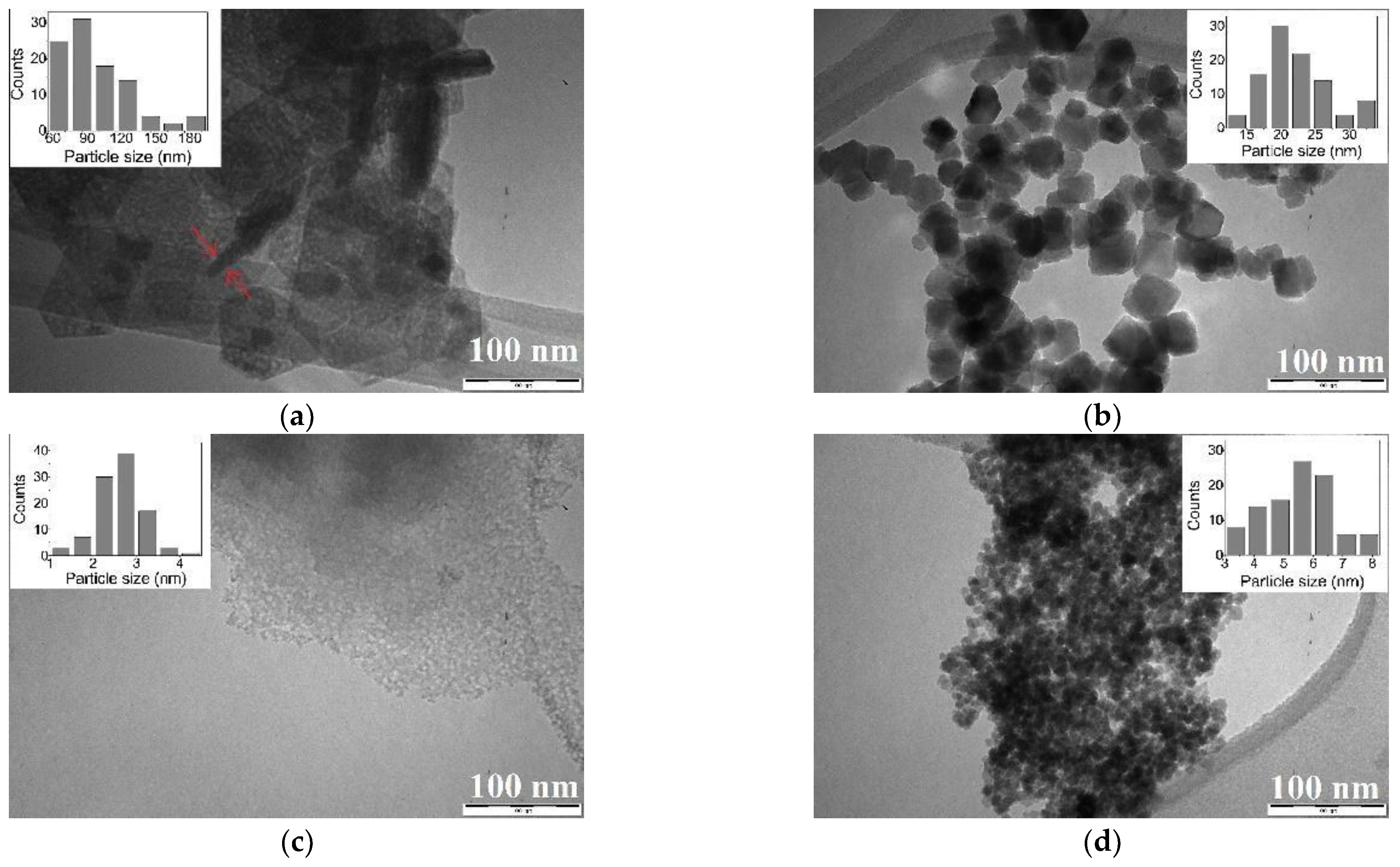
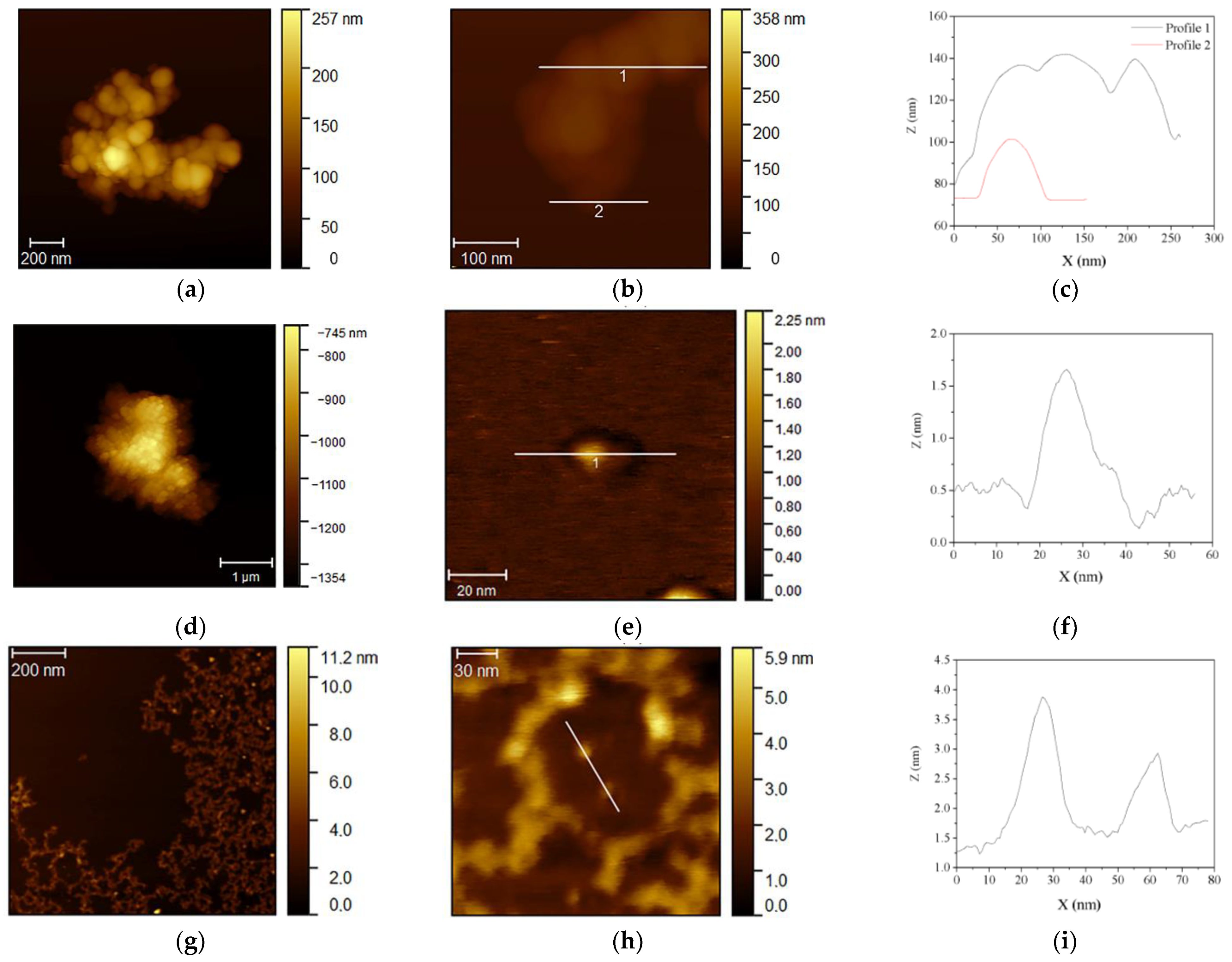
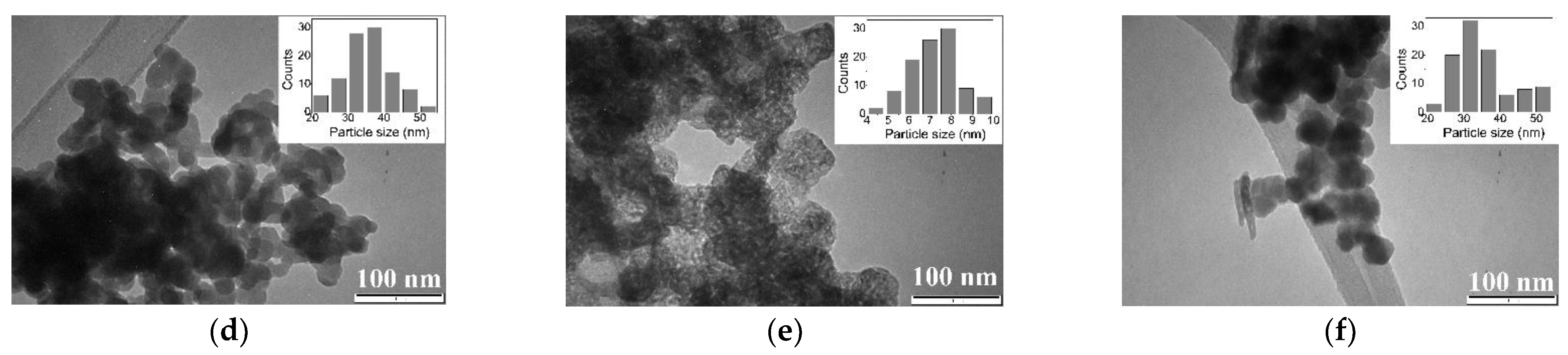
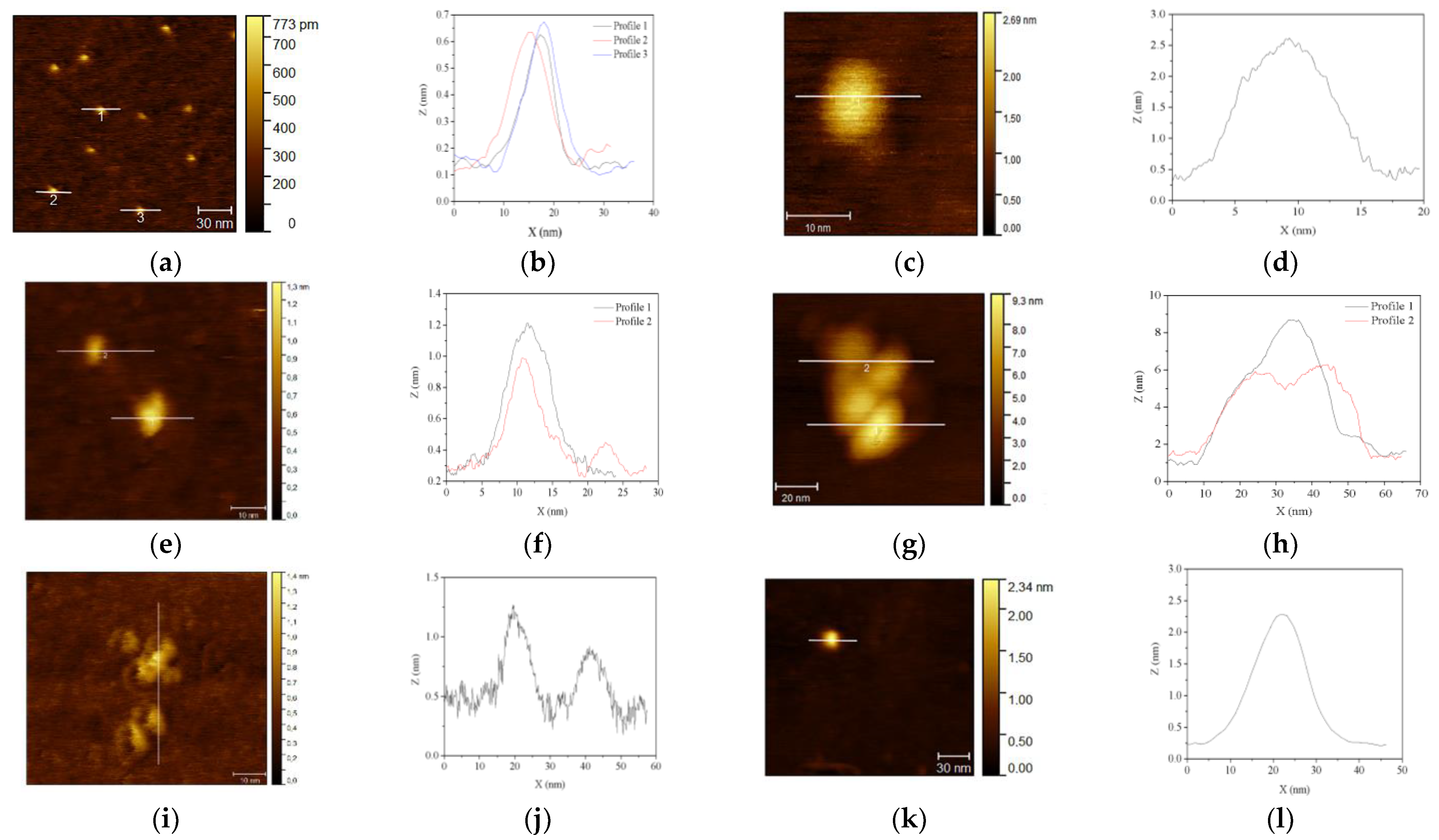
3.1. Iron Oxides NPs Obtained after the Exchange Process
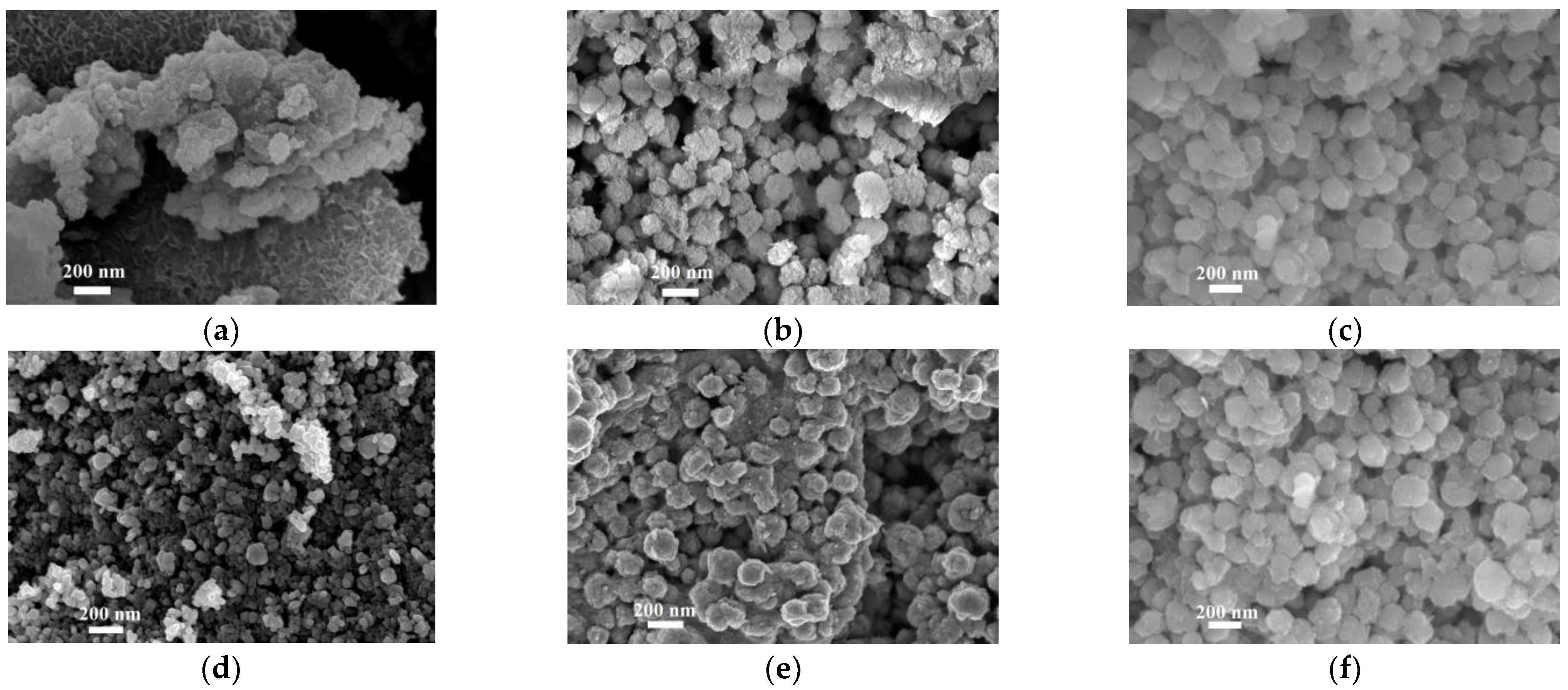
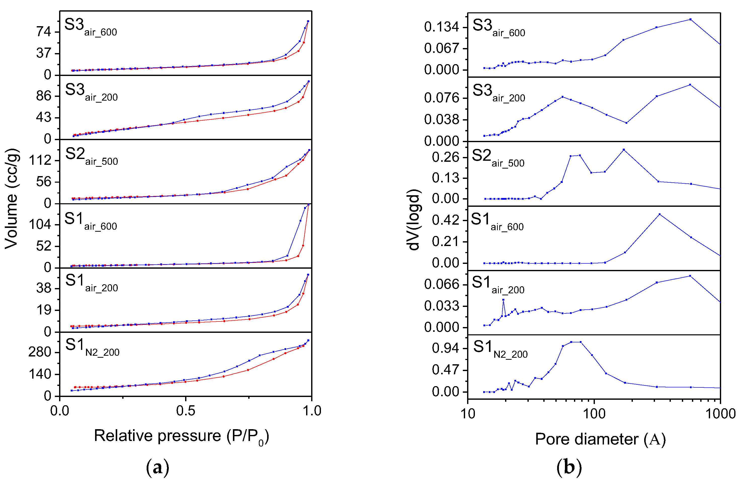
3.2. Characterization of Iron Oxides Nanoparticles Obtained by Calcination Treatments
4. Conclusions
Supplementary Materials
Author Contributions
Funding
Acknowledgments
Conflicts of Interest
References
- Cornell, R.M.; Schwertmann, U. The Iron Oxides; John Wiley & Sons: Hoboken, NJ, USA, 2003; ISBN 9783527302741. [Google Scholar]
- Fu, C.; Ravindra, N.M. Magnetic iron oxide nanoparticles: Synthesis and applications. Bioinspir. Biomim. Nanobiomater. 2012, 1, 229–244. [Google Scholar] [CrossRef]
- Ling, D.; Lee, N.; Hyeon, T. Chemical synthesis and assembly of uniformly sized iron oxide nanoparticles for medical applications. Acc. Chem. Res. 2015, 48, 1276–1285. [Google Scholar] [CrossRef] [PubMed]
- Meng Lin, M.; Kim, H.-H.; Kim, H.; Muhammed, M.; Kyung Kim, D. Iron oxide-based nanomagnets in nanomedicine: Fabrication and applications. Nano Rev. 2010, 1, 4883. [Google Scholar] [CrossRef]
- Gou, X.; Wang, G.; Park, J.; Liu, H.; Yang, J. Monodisperse hematite porous nanospheres: Synthesis, characterization, and applications for gas sensors. Nanotechnology 2008, 19, 125606. [Google Scholar] [CrossRef] [PubMed]
- Chaudhari, S.; Srinivasan, M. 1D hollow α-Fe2O3 electrospun nanofibers as high performance anode material for lithium ion batteries. J. Mater. Chem. 2012, 22, 23049–23056. [Google Scholar] [CrossRef]
- Hashimoto, H.; Ukita, M.; Sakuma, R.; Nakanishi, M.; Fujii, T.; Imanishi, N.; Takada, J. Bio-inspired 2-line ferrihydrite as a high-capacity and high-rate-capability anode material for lithium-ion batteries. J. Power Source 2016, 328, 503–509. [Google Scholar] [CrossRef]
- Pariona, N.; Martinez, A.I.; Hdz-García, H.M.; Cruz, L.A.; Hernandez-Valdes, A. Effects of hematite and ferrihydrite nanoparticles on germination and growth of maize seedlings. Saudi J. Biol. Sci. 2017, 24, 1547–1554. [Google Scholar] [CrossRef] [PubMed]
- Mohapatra, M.; Anand, S. Synthesis and applications of nano-structured iron oxides/hydroxides—A review. Int. J. Eng. Sci. Technol. 2011, 2, 127–146. [Google Scholar] [CrossRef]
- Sun, S.N.; Wei, C.; Zhu, Z.Z.; Hou, Y.L.; Venkatraman, S.S.; Xu, Z.C. Magnetic iron oxide nanoparticles: Synthesis and surface coating techniques for biomedical applications. Chin. Phys. B 2014, 23, 037503. [Google Scholar] [CrossRef]
- Shokrollahi, H. A review of the magnetic properties, synthesis methods and applications of maghemite. J. Magn. Magn. Mater. 2017, 426, 74–81. [Google Scholar] [CrossRef]
- Iacoboni, I.; Perrozzi, F.; Macera, L.; Taglieri, G.; Ottaviano, L.; Fioravanti, G. In situ syntheses of hydroxyapatite-grafted graphene oxide composites. J. Biomed. Mater. Res. Part A 2019, 107, 2026–2039. [Google Scholar] [CrossRef]
- Qin, W.; Yang, C.; Yi, R.; Gao, G. Hydrothermal synthesis and characterization of single-crystalline α-Fe2O3 nanocubes. J. Nanomater. 2011, 2011. [Google Scholar] [CrossRef]
- Li, Z.; Zhang, T.; Li, K. One-step synthesis of mesoporous two-line ferrihydrite for effective elimination of arsenic contaminants from natural water. Dalt. Trans. 2011, 40, 2062–2066. [Google Scholar] [CrossRef] [PubMed]
- Taglieri, G.; Daniele, V.; Macera, L. Synthesizing alkaline earth metal hydroxides nanoparticles through an innovative, single-step and eco-friendly method. Solid State Phenom. 2019, 286, 3–14. [Google Scholar] [CrossRef]
- Taglieri, G.; Daniele, V.; Macera, L.; Mondelli, C. Nano Ca(OH)2 synthesis using a cost-effective and innovative method: Reactivity study. J. Am. Ceram Soc. 2017, 100, 5766–5778. [Google Scholar] [CrossRef]
- Taglieri, G.; Daniele, V.; Macera, L.; Mignemi, A. Innovative and green nanolime treatment tailored to consolidate the original mortar of the façade of a medieval building in L’aquila (Italy). Constr. Build. Mater. 2019, 221. [Google Scholar] [CrossRef]
- Macera, L.; Taglieri, G.; Daniele, V.; Passacantando, M.; D’Orazio, F. Nano-Sized Fe(III) Oxide Particles Starting from an Innovative and Eco-Friendly Synthesis Method. Nanomaterials 2020, 10, 323. [Google Scholar] [CrossRef] [PubMed]
- Gotić, M.; Ivanda, M.; Popović, S.; Musić, S. Synthesis of tungsten trioxide hydrates and their structural properties. Mater. Sci. Eng. B Solid State Mater. Adv. Technol. 2000, 77, 193–201. [Google Scholar] [CrossRef]
- Apblett, A.W.; Kuriyavar, S.I.; Kiran, B.P. Preparation of micron-sized spherical porous iron oxide particles. J. Mater. Chem. 2003, 13, 983–985. [Google Scholar] [CrossRef]
- Sulistyaningsih, T.; Santosa, S.J.; Siswanta, D.; Rusdiarso, B. Synthesis and Characterization of Magnetites Obtained from Mechanically and Sonochemically Assissted Co-precipitation and Reverse Co-precipitation Methods. Int. J. Mater. Mech. Manuf. 2017, 5, 16–19. [Google Scholar] [CrossRef][Green Version]
- Schikorr, G. Über die Reaktionen zwischen Eisen, Seinen Hydroxyden und Wasser. Z. Elektrochem. Angew. Phys. Chemie 1929, 35, 65–70. [Google Scholar] [CrossRef]
- Nichterwitz, M.; Neitsch, S.; Röher, S.; Wolf, D.; Nielsch, K.; Leistner, K. Voltage-controlled on switching and manipulation of magnetization via the redox transformation of β-FeOOH nanoplatelets. J. Phys. D Appl. Phys. 2020, 53, 084001. [Google Scholar] [CrossRef]
- Chagas, P.; Da Silva, A.C.; Passamani, E.C.; Ardisson, J.D.; De Oliveira, L.C.A.; Fabris, J.D.; Paniago, R.M.; Monteiro, D.S.; Pereira, M.C. δ-FeOOH: A superparamagnetic material for controlled heat release under AC magnetic field. J. Nanopart. Res. 2013, 15, 1–7. [Google Scholar] [CrossRef]
- Soltis, J.A.; Feinberg, J.M.; Gilbert, B.; Penn, R.L. Phase Transformation and Particle-Mediated Growth in the Formation of Hematite from 2-Line Ferrihydrite. Cryst. Growth Des. 2016, 16, 922–932. [Google Scholar] [CrossRef]
- Khan, U.S.; Amanullah; Manan, A.; Khan, N.; Mahmood, A.; Rahim, A. Transformation mechanism of magnetite nanoparticles. Mater. Sci. Pol. 2015, 33, 278–285. [Google Scholar] [CrossRef]
- Kazeminezhad, I.; Mosivand, S. Phase transition of electrooxidized Fe3O4 to γ and α-Fe2O3 nanoparticles using sintering treatment. Acta Phys. Pol. A 2014, 125, 1210–1214. [Google Scholar] [CrossRef]
- Bish, D.L.; Post, J.E. Modern Powder Diffraction; Mineralogical society of America: Washington, DC, USA, 1989; pp. i–xii, ISBN 0-939950-24-3; ISBN 13 978-0-939950-24-9. [Google Scholar]
- Qazi, S.J.S.; Rennie, A.R.; Cockcroft, J.K.; Vickers, M. Use of wide-angle X-ray diffraction to measure shape and size of dispersed colloidal particles. J. Colloid Interface Sci. 2009, 338, 105–110. [Google Scholar] [CrossRef] [PubMed]
- Polyakov, A.Y.; Goldt, A.E.; Sorkina, T.A.; Perminova, I.V.; Pankratov, D.A.; Goodilin, E.A.; Tretyakov, Y.D. Constrained growth of anisotropic magnetic δ-FeOOH nanoparticles in the presence of humic substances. CrystEngComm 2012, 14, 8097–8102. [Google Scholar] [CrossRef]
- Tüysüz, H.; Salabaş, E.L.; Weidenthaler, C.; Schüth, F. Synthesis and magnetic investigation of ordered mesoporous two-line ferrihydrite. J. Am. Chem. Soc. 2008, 130, 280–287. [Google Scholar] [CrossRef]
- Ceo, C.O. Nanomaterials How to analyze nanomaterials using powder diffraction and the Powder Diffraction File TM; Technical Bulletin—Nanomaterials; International Centre for Diffraction Data (ICDD): Newtown Square, PA, USA.
- Zhang, X.; Chen, Y.; Zhao, N.; Liu, H.; Wei, Y. Citrate modified ferrihydrite microstructures: Facile synthesis, strong adsorption and excellent Fenton-like catalytic properties. RSC Adv. 2014, 4, 21575–21583. [Google Scholar] [CrossRef]
- Taglieri, G.; Felice, B.; Daniele, V.; Ferrante, F. Mg(OH)2 nanoparticles produced at room temperature by an innovative, facile, and scalable synthesis route. J. Nanopart. Res. 2015, 17. [Google Scholar] [CrossRef]
- Patra, A.K.; Kim, D. Smart design of self-assembled mesoporous α-FeOOH nanoparticles: High-surface-area sorbent for Hg2+ from wastewater. ACS Sustain. Chem. Eng. 2017, 5, 1272–1279. [Google Scholar] [CrossRef]
- Thommes, M.; Kaneko, K.; Neimark, A.V.; Olivier, J.P.; Rodriguez-Reinoso, F.; Rouquerol, J.; Sing, K.S.W. Physisorption of gases, with special reference to the evaluation of surface area and pore size distribution (IUPAC Technical Report). Pure Appl. Chem. 2015, 87, 1051–1069. [Google Scholar] [CrossRef]
- Ambroz, F.; Macdonald, T.J.; Martis, V.; Parkin, I.P. Evaluation of the BET Theory for the Characterization of Meso and Microporous MOFs. Small Methods 2018, 2, 1800173. [Google Scholar] [CrossRef]
- Křížek, M.; Pechoušek, J.; Tuček, J.; Šafářová, K.; Medřík, I.; Machala, L. Iron oxide nanoparticle powders with high surface area. In Proceedings of the AIP Conference Proceedings; American Institute of Physics: Melville, NY, USA, 2012; Volume 1489, pp. 88–94. [Google Scholar]
- Di Iorio, E.; Colombo, C.; Cheng, Z.; Capitani, G.; Mele, D.; Ventruti, G.; Angelico, R. Characterization of magnetite nanoparticles synthetized from Fe(II)/nitrate solutions for arsenic removal from water. J. Environ. Chem. Eng. 2019, 7, 102986. [Google Scholar] [CrossRef]
- Iconaru, S.L.; Guégan, R.; Popa, C.L.; Motelica-Heino, M.; Ciobanu, C.S.; Predoi, D. Magnetite (Fe3O4) nanoparticles as adsorbents for As and Cu removal. Appl. Clay Sci. 2016, 134, 128–135. [Google Scholar] [CrossRef]
- Mishra, A.K.; Ramaprabhu, S. Nano magnetite decorated multiwalled carbon nanotubes: A robust nanomaterial for enhanced carbon dioxide adsorption. Energy Environ. Sci. 2011, 4, 889–895. [Google Scholar] [CrossRef]
- Srivastava, V.; Singh, P.; Weng, C.; Sharma, Y. Economically viable synthesis of Fe3O4 nanoparticles and their characterization. Pol. J. Chem. Technol. 2011, 13, 1–5. [Google Scholar] [CrossRef]
- Tadic, M.; Kopanja, L.; Panjan, M.; Lazovic, J.; Tadic, B.V.; Stanojevic, B.; Motte, L. Rhombohedron and plate-like hematite (α-Fe2O3) nanoparticles: Synthesis, structure, morphology, magnetic properties and potential biomedical applications for MRI. Mater. Res. Bull. 2021, 133. [Google Scholar] [CrossRef]
- Cudennec, Y.; Lecerf, A. The transformation of ferrihydrite into goethite or hematite, revisited. J. Solid State Chem. 2006, 179, 716–722. [Google Scholar] [CrossRef]
- Schwertmann, U.; Friedl, J.; Stanjek, H. From Fe(III) ions to ferrihydrite and then to hematite. J. Colloid Interface Sci. 1999, 209, 215–223. [Google Scholar] [CrossRef] [PubMed]
- Pariona, N.; Camacho-Aguilar, K.I.; Ramos-González, R.; Martinez, A.I.; Herrera-Trejo, M.; Baggio-Saitovitch, E. Magnetic and structural properties of ferrihydrite/hematite nanocomposites. J. Magn. Magn. Mater. 2016, 406, 221–227. [Google Scholar] [CrossRef]
- Thommes, M. Physical Adsorption Characterization of Nanoporous Materials. Chem. Ing. Tech. 2010, 82, 1059–1073. [Google Scholar] [CrossRef]
- Yu, S.; Bo, J.; Fengli, L.; Jiegang, L. Structure and fractal characteristic of micro- and meso-pores in low, middle-rank tectonic deformed coals by CO2 and N2 adsorption. Microporous Mesoporous Mater. 2017, 253, 191–202. [Google Scholar] [CrossRef]
- Shan, C.; Zhang, T.; Liang, X.; Zhang, Z.; Wang, M.; Zhang, K.; Zhu, H. On the fundamental difference of adsorption-pores systems between vitrinite- and inertinite-rich anthracite derived from the southern Sichuan basin, China. J. Nat. Gas Sci. Eng. 2018, 53, 32–44. [Google Scholar] [CrossRef]
- Dehbi, A.; Dehmani, Y.; Omari, H.; Lammini, A.; Elazhari, K.; Abdallaoui, A. Hematite iron oxide nanoparticles (α-Fe2O3): Synthesis and modelling adsorption of malachite green. J. Environ. Chem. Eng. 2020, 8, 103394. [Google Scholar] [CrossRef]


| Suspension Sample | Oxidation State of Initial Reagents | Atmosphere | Expected Compounds | Reaction |
|---|---|---|---|---|
| S1N2 | Fe (II) | N2 | δ-FeOOH | 5 |
| S1air | air | Fe3O4 | 4 | |
| S2N2 | Fe(III) | N2 | Fe5HO8⋅4H2O | 6 |
| S2air | air | 6 | ||
| S3N2 | Fe(II) + Fe(III) | N2 | Fe3O4 | 7 |
| S3air | air | 7 |
| Suspension Sample | pH 0 min | pH 10 min | ΔCC (%) 1 min | ΔCC (%) 10 min | RCC (mg/L) | NPs Produced in 10 min (g) | Yield (%) |
|---|---|---|---|---|---|---|---|
| S1N2 | 2.5 | 9.1 | 96.8 | 99.1 | 29.7 | 44 | 92 |
| S1air | 2.5 | 7.5 | 96.9 | 99.3 | 27.3 | 45 | 94 |
| S2N2 | 1.6 | 7.5 | 99.2 | 99.9 | 21.4 | 41 | 94 |
| S2air | 1.6 | 7.5 | 99.1 | 99.9 | 21.6 | 42 | 95 |
| S3N2 | 1.6 | 7.5 | 98.2 | 99.5 | 24.5 | 36 | 94 |
| S3air | 1.6 | 7.5 | 98.3 | 99.7 | 23.4 | 37 | 96 |
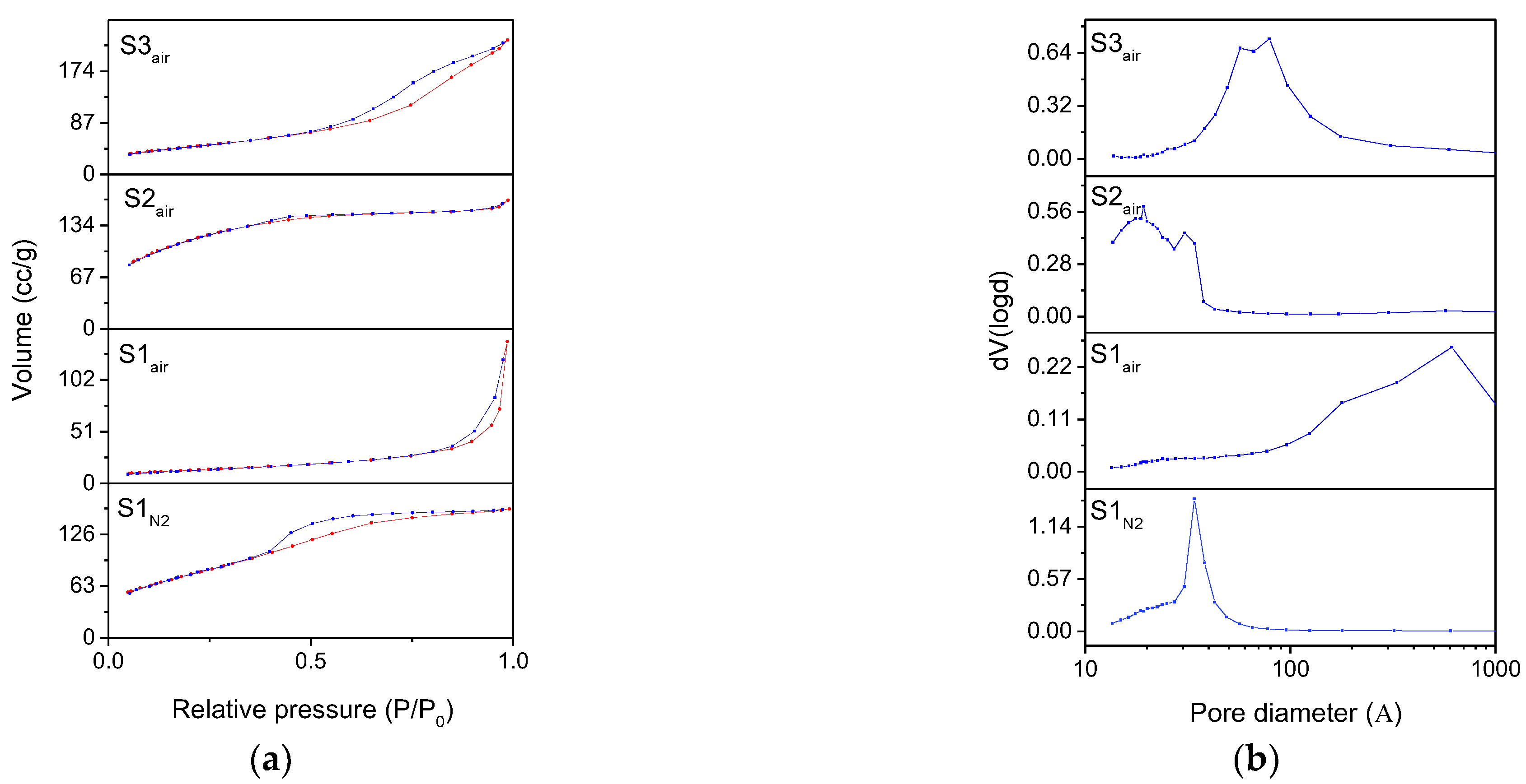
| Iron Oxyhydroxide S1N2 | Magnetite S1air | Ferrihydrite S2air | Magnetite S3air | |
|---|---|---|---|---|
| BET surface area (m2/g) | 271 | 46 | 420 | 169 |
| BJH pore diameter Dv(d) (nm) | 3.41 | 2.38 | 1.50 | 5.69 |
| BJH pore volume (cc/g) | 0.25 | 0.22 | 0.24 | 0.36 |
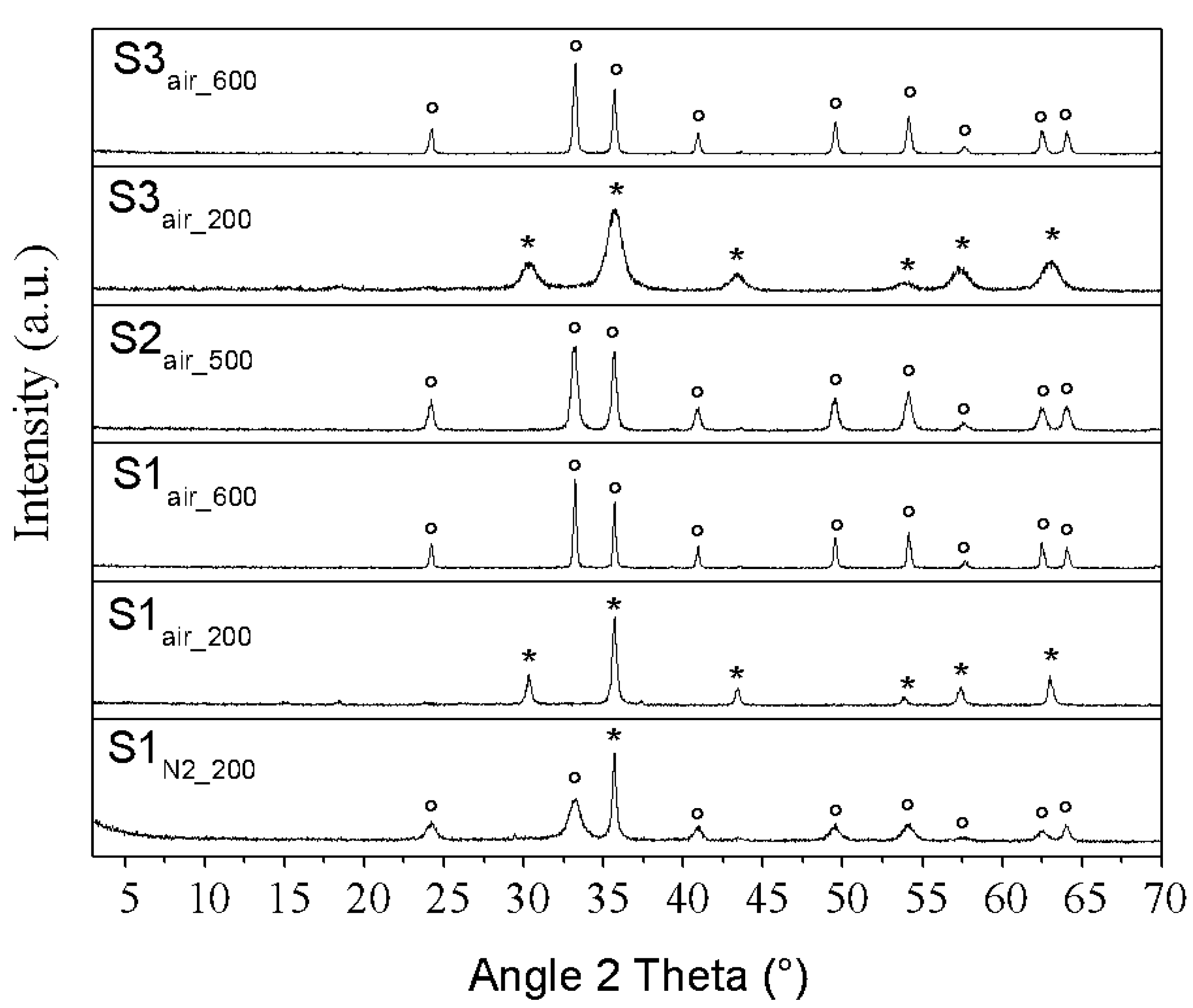
| Starting Sample | S1N2 | S1air | S2air | S3air | ||
|---|---|---|---|---|---|---|
| Calcination temperature | 200 °C | 200 °C | 600 °C | 500 °C | 200 °C | 600 °C |
| Obtained Compound | Hematite | Maghemite | Hematite | Hematite | Maghemite | Hematite |
| BET surface area (m2/g) | 205 | 20 | 22 | 58 | 37 | 34 |
| BJH pore diameter Dv(d) (nm) | 5.67 | 1.91 | 32.99 | 6.53 | 3.43 | 3.91 |
| BJH pore volume (cc/g) | 0.60 | 0.08 | 0.24 | 0.22 | 0.21 | 0.14 |
Publisher’s Note: MDPI stays neutral with regard to jurisdictional claims in published maps and institutional affiliations. |
© 2021 by the authors. Licensee MDPI, Basel, Switzerland. This article is an open access article distributed under the terms and conditions of the Creative Commons Attribution (CC BY) license (http://creativecommons.org/licenses/by/4.0/).
Share and Cite
Macera, L.; Daniele, V.; Mondelli, C.; Capron, M.; Taglieri, G. New Sustainable, Scalable and One-Step Synthesis of Iron Oxide Nanoparticles by Ion Exchange Process. Nanomaterials 2021, 11, 798. https://doi.org/10.3390/nano11030798
Macera L, Daniele V, Mondelli C, Capron M, Taglieri G. New Sustainable, Scalable and One-Step Synthesis of Iron Oxide Nanoparticles by Ion Exchange Process. Nanomaterials. 2021; 11(3):798. https://doi.org/10.3390/nano11030798
Chicago/Turabian StyleMacera, Ludovico, Valeria Daniele, Claudia Mondelli, Marie Capron, and Giuliana Taglieri. 2021. "New Sustainable, Scalable and One-Step Synthesis of Iron Oxide Nanoparticles by Ion Exchange Process" Nanomaterials 11, no. 3: 798. https://doi.org/10.3390/nano11030798
APA StyleMacera, L., Daniele, V., Mondelli, C., Capron, M., & Taglieri, G. (2021). New Sustainable, Scalable and One-Step Synthesis of Iron Oxide Nanoparticles by Ion Exchange Process. Nanomaterials, 11(3), 798. https://doi.org/10.3390/nano11030798