
Improvement in Tensile Quasi-Static and Fatigue Properties of Carbon Fiber-Reinforced Epoxy Laminates with Matrices Modified by Carbon Nanotubes and Graphene Nanoplatelets Hybrid Nanofillers

Abstract
:1. Introduction
2. Materials and Methods
2.1. Materials
2.2. Nano-Modified Epoxies
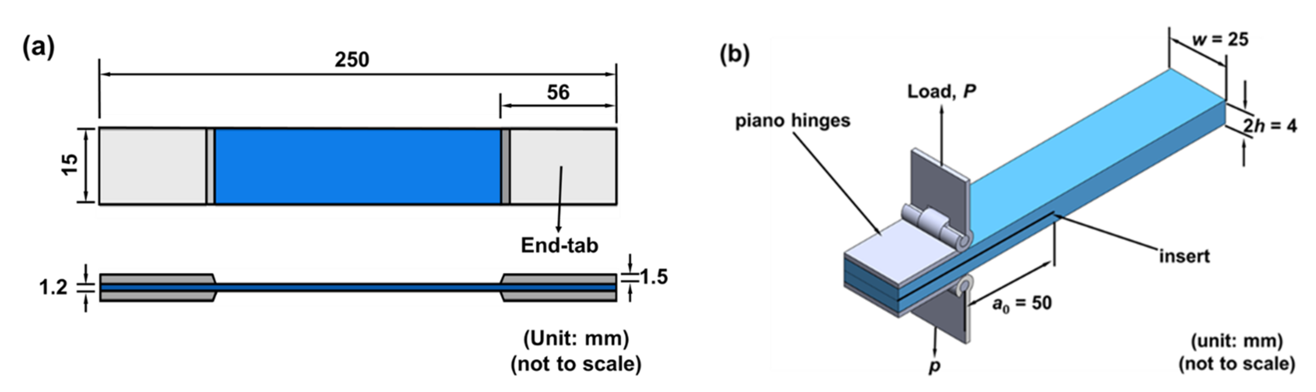
2.3. Fabrication of Nano-CFEP Laminate Specimens
2.4. Tests of Mechanical Properties
3. Results
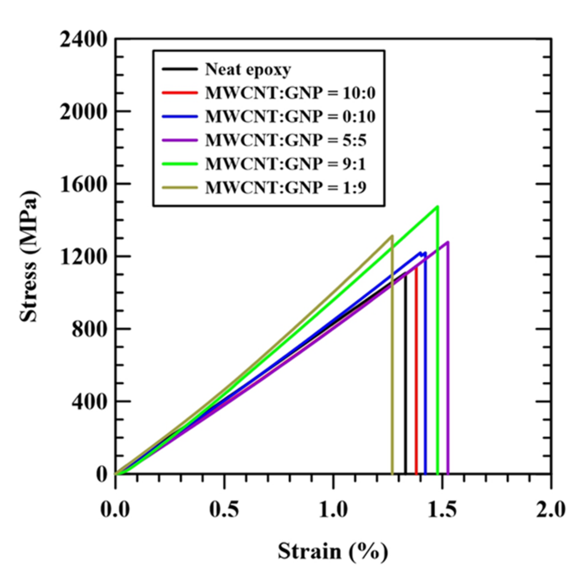
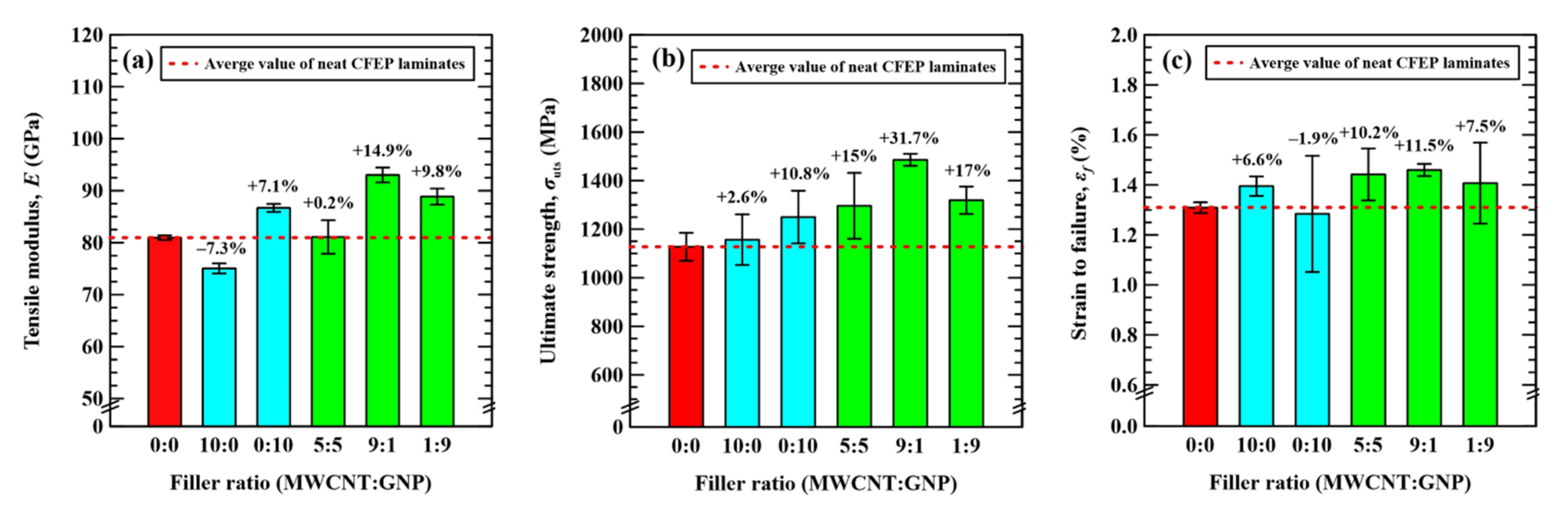
3.1. Quasi-Static Mechanical Properties
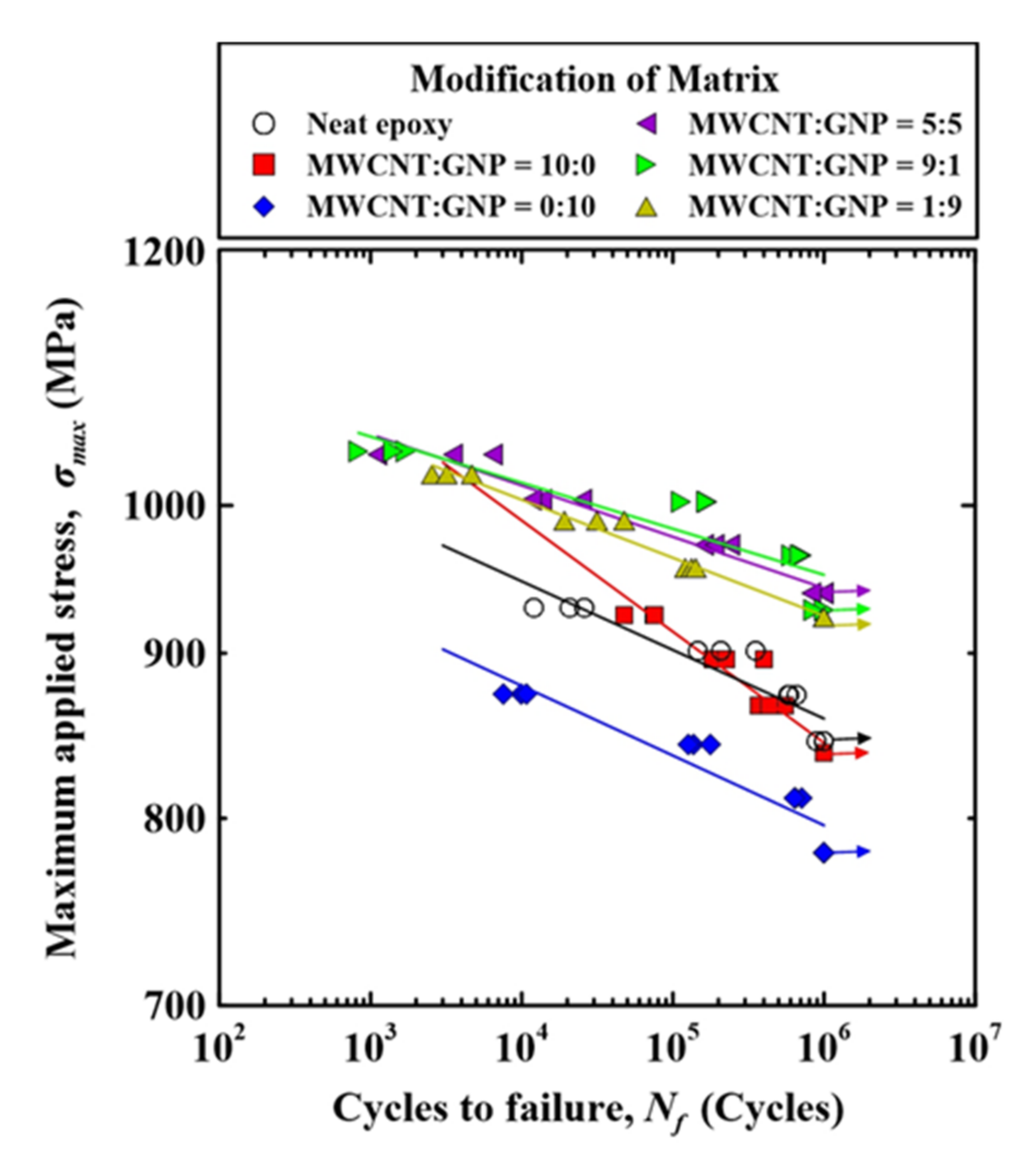
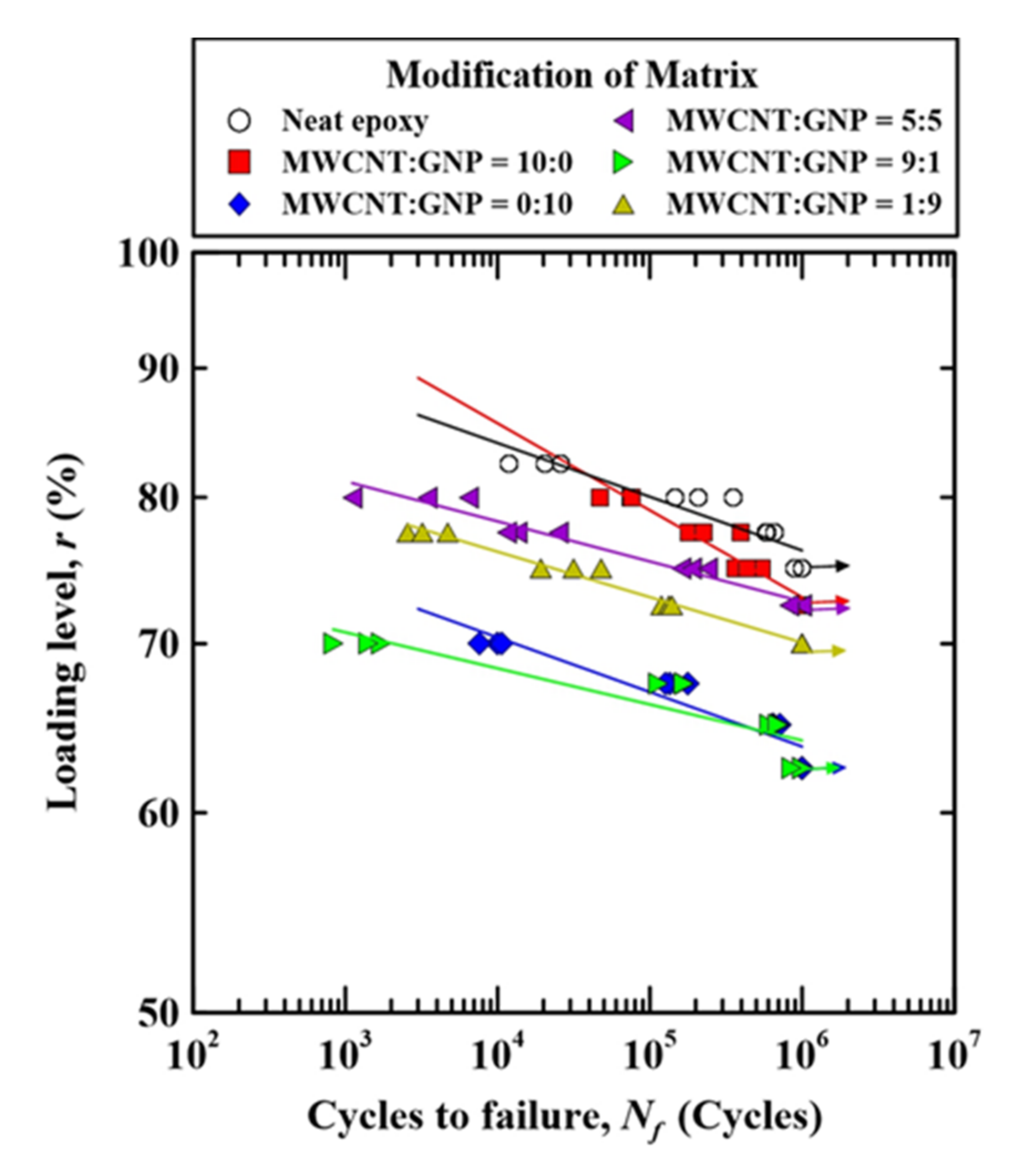
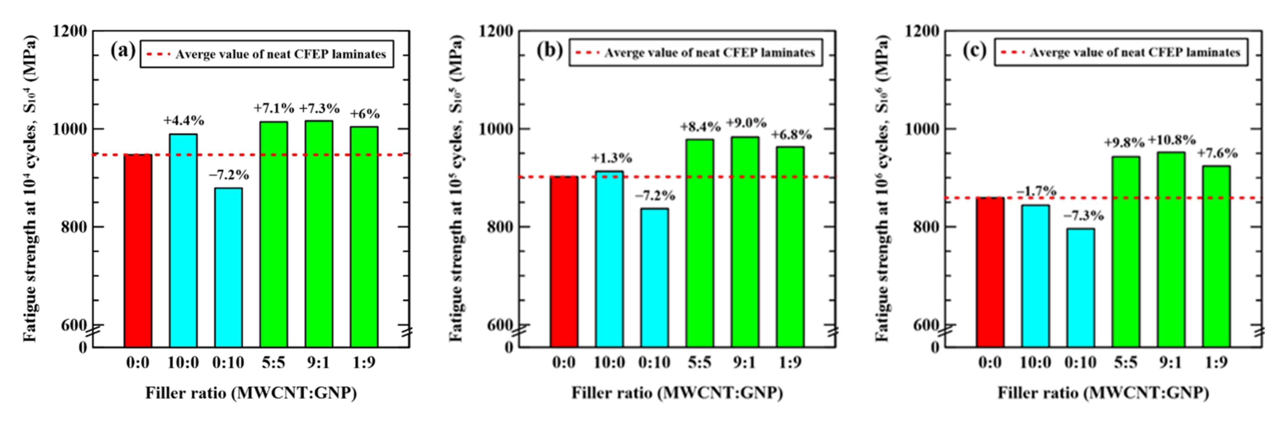
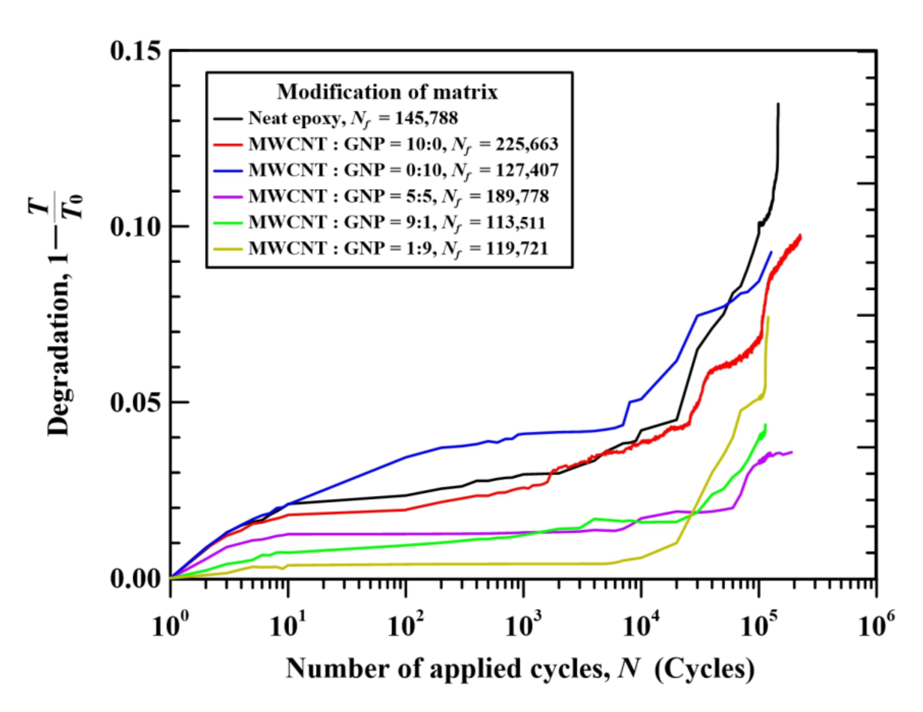
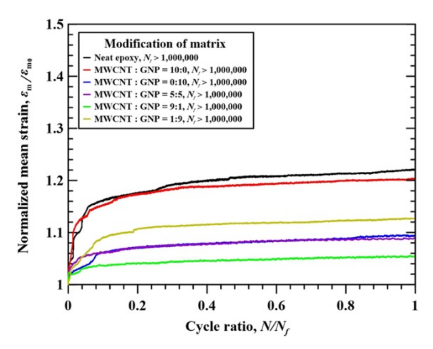
3.2. Fatigue Properties
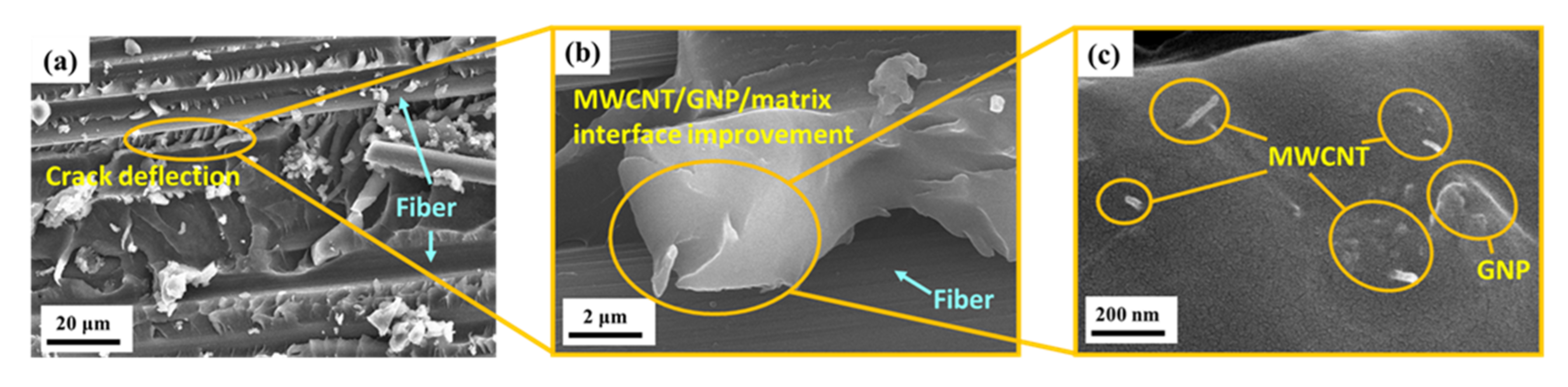
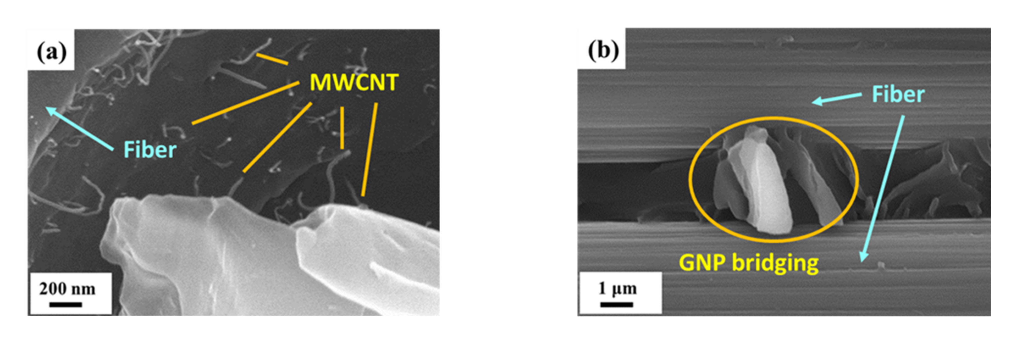
3.3. Observation of Fracture Surfaces
4. Discussion
5. Conclusions
- The nano-CFEP laminate specimens with matrices modified under a MWCNT:GNP ratio of 9:1 have a higher monotonic modulus and strength than the CFEP laminate specimens with matrices modified under other conditions;
- Adding individual types of nanoparticles has a slight influence on the tensile fatigue strength of CFEP laminates. However, the CFEP laminate specimens with matrices modified by hybrid nanoparticles display a significant improvement in fatigue strength compared to the neat CFEP specimens or specimens modified with individual types of nanoparticles;
- Examining the evolution of stiffness-based degradation shows that polymer matrices modified by hybrid nanoparticles can effectively shift the degradation to lower values;
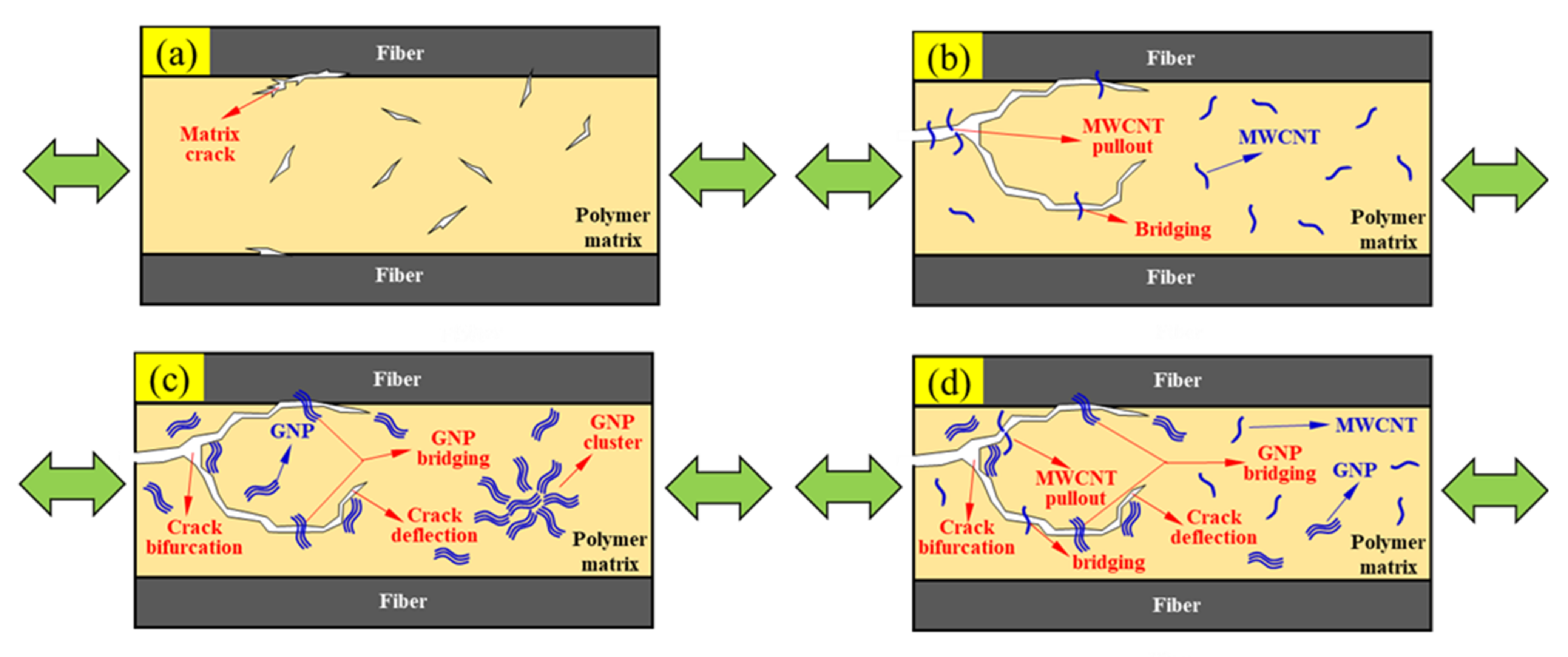
- The synergistic effect of MWCNTs and GNPs on the mode I fracture toughness of CFEP composites has been experimentally verified, implying that the hybrid nanoparticle system employed in the matrix modification can improve the resistance to interfacial debonding and delamination propagation;
- The pushout effect of MWCNTs and the crack deflection effect of GNPs are the main enhancement mechanisms at the matrix microcrack dominant stage. The bridging effect of nanoparticles at the fiber/matrix interfaces retards the growth of interfacial debonding, further improving the fatigue strength.
Author Contributions
Funding
Conflicts of Interest
References
- Talreja, R. Fatigue of composite materials: Damage mechanisms and fatigue-life diagrams. Proc. R. Soc. Lond. A Mat. 1981, 378, 461–475. [Google Scholar]
- Gamstedt, E.K.; Talreja, R. Fatigue damage mechanisms in unidirectional carbon-fibre-reinforced plastics. J. Mater. Sci. 1999, 34, 2535–2546. [Google Scholar] [CrossRef]
- Manjunatha, C.M.; Taylor, A.C.; Kinloch, A.J.; Sprenger, S. The tensile fatigue behaviour of a silica nanoparticle-modified glass fibre reinforced epoxy composite. Compos. Sci. Technol. 2010, 70, 193–199. [Google Scholar] [CrossRef] [Green Version]
- Knoll, J.B.; Riecken, B.T.; Kosmann, N.; Chandrasekaran, S.; Schulte, K.; Fiedler, B. The effect of carbon nanoparticles on the fatigue performance of carbon fibre reinforced epoxy. Compos. Part A Appl. Sci. Manuf. 2014, 67, 233–240. [Google Scholar] [CrossRef]
- Chen, L.; Ifju, P.G.; Sankar, B.V. A novel double cantilever beam test for stitched composite laminates. J. Compos. Mater. 2000, 35, 1137–1149. [Google Scholar] [CrossRef]
- Ravandi, M.; Teo, W.S.; Tran, L.Q.N.; Yong, M.S.; Tay, T.E. Low velocity impact performance of stitched flax/epoxy composite laminates. Compos. Part B Eng. 2017, 117, 89–100. [Google Scholar] [CrossRef]
- Mouritz, A.P. Review of Z-pinned composite laminates. Compos. Part A Appl. Sci. Manuf. 2007, 38, 2383–2397. [Google Scholar] [CrossRef]
- Francesconi, L.; Aymerich, F. Effect of Z-pinning on the impact resistance of composite laminates with different layups. Compos. Part A Appl. Sci. Manuf. 2018, 114, 136–148. [Google Scholar] [CrossRef]
- Virakthi, A.; Kwon, S.; Lee, S.W.; Robeson, M.E. Delamination resistance of composite laminated structures reinforced with angled, threaded, and anchored Z-pins. J. Compos. Mater. 2019, 53, 1507–1519. [Google Scholar] [CrossRef]
- Mouritz, A.P.; Bannister, M.K.; Falzon, P.J.; Leong, K.H. Review of applications for advanced three-dimensional fibre textile composites. Compos. Part Appl. Sci. Manuf. 1999, 30, 1445–1461. [Google Scholar] [CrossRef]
- Bandaru, A.K.; Chavan, V.V.; Ahmad, S.; Alagirusamy, R.; Bhatnagar, N. Low velocity impact response of 2D and 3D Kevlar/polypropylene composites. Int. J. Impact Eng. 2016, 93, 136–143. [Google Scholar] [CrossRef]
- De Cicco, D.; Asaee, Z.; Taheri, F. Use of nanoparticles for enhancing the interlaminar properties of fiber-reinforced composites and adhesively bonded joints—A review. Nanomaterials 2017, 7, 360. [Google Scholar] [CrossRef] [Green Version]
- Saghafi, H.; Fotouhi, M.; Minak, G. Improvement of the impact properties of composite laminates by means of nano-modification of the matrix—A review. Appl. Sci. 2018, 8, 2406. [Google Scholar] [CrossRef] [Green Version]
- Kumar, M.; Kumar, P.; Bhadauria, S.S. Interlaminar fracture toughness and fatigue fracture of continuous fiber-reinforced polymer composites with carbon-based nanoreinforcements: A review. Polym. Plast. Technol. 2020, 59, 1041–1076. [Google Scholar] [CrossRef]
- Tang, Y.; Ye, L.; Zhang, Z.; Friedrich, K. Interlaminar fracture toughness and CAI strength of fibre-reinforced composites with nanoparticles–A review. Compos. Sci. Technol. 2013, 86, 26–37. [Google Scholar] [CrossRef]
- Drescher, P.; Thomas, M.; Borris, J.; Riedel, U.; Arlt, C. Strengthening fibre/matrix interphase by fibre surface modification and nanoparticle incorporation into the matrix. Compos. Sci. Technol. 2013, 74, 60–66. [Google Scholar] [CrossRef]
- Domun, N.; Hadavinia, H.; Zhang, T.; Sainsbury, T.; Liaghat, G.H.; Vahid, S. Improving the fracture toughness and the strength of epoxy using nanomaterials–a review of the current status. Nanoscale 2015, 7, 10294–10329. [Google Scholar] [CrossRef] [Green Version]
- Manjunatha, C.M.; Chandra, A.A.; Jagannathan, N. Fracture and fatigue behavior of polymer nanocomposites—A review. J. Indian Inst. Sci. A Eng. 2015, 95, 249–266. [Google Scholar]
- Rajanish, M.; Nanjundaradhya, N.V.; Sharma, R.S.; Shivananda, H.K.; Hegde, A. Directional Interlaminar Shear Strength (ILSS) of nano-modified epoxy/unidirectional glass fibre composite. AIMS Matet. Sci. 2018, 5, 603–613. [Google Scholar] [CrossRef]
- Di Boon, Y.; Joshi, S.C. A review of methods for improving interlaminar interfaces and fracture toughness of laminated composites. Mater. Today Commun. 2020, 22, 100830. [Google Scholar] [CrossRef]
- Bansal, T.; Malik, S.; Batra, T.; Shah, M.; Gupta, A.; Khan, K.L.A. Review of effect of nanofillers on FRP composites. In Recent Advances in Mechanical Engineering; Kumar, A., Pal, A., Kachhwaha, S.S., Jain, P.K., Eds.; Springer: Singapore, 2021; pp. 411–417. [Google Scholar]
- Grimmer, C.S.; Dharan, C.K.H. High-cycle fatigue of hybrid carbon nanotube/glass fiber/polymer composites. J. Mater. Sci. 2008, 43, 4487–4492. [Google Scholar] [CrossRef]
- Davis, D.C.; Wilkerson, J.W.; Zhu, J.; Ayewah, D.O. Improvements in mechanical properties of a carbon fiber epoxy composite using nanotube science and technology. Compos. Struct. 2010, 92, 2653–2662. [Google Scholar] [CrossRef]
- Chang, M.S. An investigation on the dynamic behavior and thermal properties of MWCNTs/FRP laminate composites. J. Reinf. Plast. Compos. 2010, 29, 3593–3599. [Google Scholar] [CrossRef]
- Böger, L.; Sumfleth, J.; Hedemann, H.; Schulte, K. Improvement of fatigue life by incorporation of nanoparticles in glass fibre reinforced epoxy. Compos. Part A Appl. Sci. Manuf. 2010, 41, 1419–1424. [Google Scholar] [CrossRef]
- Takeda, T.; Fan, W.; Feng, Q.P.; Fu, S.Y.; Narita, F.; Shindo, Y. Cryogenic mechanical properties of woven glass/epoxy composites modified with multi-walled carbon nanotube and n-butyl glycidyl ether under tensile static and cyclic loadings. Cryogenics 2013, 58, 33–37. [Google Scholar] [CrossRef]
- Borrego, L.P.; Costa, J.D.M.; Ferreira, J.A.M.; Silva, H. Fatigue behaviour of glass fibre reinforced epoxy composites enhanced with nanoparticles. Compos. Part B Eng. 2014, 62, 65–72. [Google Scholar] [CrossRef]
- Yavari, F.; Rafiee, M.A.; Rafiee, J.; Yu, Z.Z.; Koratkar, N. Dramatic increase in fatigue life in hierarchical graphene composites. ACS Appl. Mater. Inter. 2010, 2, 2738–2743. [Google Scholar] [CrossRef] [Green Version]
- Shen, M.Y.; Chang, T.Y.; Hsieh, T.H.; Li, Y.L.; Chiang, C.L.; Yang, H.; Yip, M.C. Mechanical properties and tensile fatigue of graphene nanoplatelets reinforced polymer nanocomposites. J. Nanomater. 2013, 2013, 565401. [Google Scholar] [CrossRef]
- Bourchak, M.; Algarni, A.; Khan, A.; Khashaba, U. Effect of SWCNTs and graphene on the fatigue behavior of antisymmetric GFRP laminate. Compos. Sci. Technol. 2018, 167, 164–173. [Google Scholar] [CrossRef]
- Leopold, C.; Just, G.; Koch, I.; Schetle, A.; Kosmann, J.B.; Gude, M.; Fiedler, B. Damage mechanisms of tailored few-layer graphene modified CFEP cross-ply laminates. Compos. Part A Appl. Sci. Manuf. 2019, 117, 332–344. [Google Scholar] [CrossRef]
- Tareq, M.S.; Jony, B.; Zainuddin, S.; Al Ahsan, M.; Hosur, M.V. Fatigue analysis and fracture toughness of graphene reinforced carbon fibre polymer composites. Fatigue Fract. Eng. M. 2021, 44, 461–474. [Google Scholar] [CrossRef]
- Grimmer, C.S.; Dharan, C.K.H. Enhancement of delamination fatigue resistance in carbon nanotube reinforced glass fiber/polymer composites. Compos. Sci. Technol. 2010, 70, 901–908. [Google Scholar] [CrossRef]
- Romhany, G.; Szebényi, G. Interlaminar fatigue crack growth behavior of MWCNT/carbon fiber reinforced hybrid composites monitored via newly developed acoustic emission method. Express Polym. Lett. 2012, 6, 572–580. [Google Scholar] [CrossRef]
- Fenner, J.S.; Daniel, I.M. Hybrid nanoreinforced carbon/epoxy composites for enhanced damage tolerance and fatigue life. Compos. Part A Appl. Sci. Manuf. 2014, 65, 47–56. [Google Scholar] [CrossRef]
- Kadlec, M.; Nováková, L.; Mlch, I.; Guadagno, L. Fatigue delamination of a carbon fabric/epoxy laminate with carbon nanotubes. Compos. Sci. Technol. 2016, 131, 32–39. [Google Scholar] [CrossRef]
- Kumar, A.; Sharma, K.; Dixit, A.R. A review on the mechanical properties of polymer composites reinforced by carbon nanotubes and graphene. Carbon Lett. 2021, 31, 149–165. [Google Scholar] [CrossRef]
- Zheng, X.N.; Yin, X.Y.; Wang, B.; Ma, M.G. Review on the synergetic combination of 1D/2D functional nanocomposites. Sci. Adv. Mater. 2020, 12, 613–627. [Google Scholar] [CrossRef]
- Szeluga, U.; Kumanek, B.; Trzebicka, B. Synergy in hybrid polymer/nanocarbon composites. A review. Compos. Part A Appl. Sci. Manuf. 2015, 73, 204–231. [Google Scholar] [CrossRef]
- Liang, X.; Cheng, Q. Synergistic reinforcing effect from graphene and carbon nanotubes. Compos. Commun. 2018, 10, 122–128. [Google Scholar] [CrossRef]
- Jen, Y.M.; Chang, H.H.; Lu, C.M.; Liang, S.Y. Temperature-Dependent Synergistic Effect of Multi-Walled Carbon Nanotubes and Graphene Nanoplatelets on the Tensile Quasi-Static and Fatigue Properties of Epoxy Nanocomposites. Polymers 2021, 13, 84. [Google Scholar] [CrossRef]
- ASTM International. Standard Test Method for Tensile Properties of Polymer Matrix Composite Materials; D3039/D3039M-17; ASTM International: West Conshohocken, PA, USA, 2017; Available online: https://www.astm.org/d3039_d3039m-17.html (accessed on 23 November 2021).
- ASTM International. Standard Test Method for Mode I Interlaminar Fracture Toughness of Unidirectional Fiber-Reinforced Polymer Matrix Composites; D5528-13; ASTM International: West Conshohocken, PA, USA, 2013; Available online: https://www.astm.org/d5528-13.html (accessed on 23 November 2021).
- ASTM International. Standard Test Method for Tension-Tension Fatigue of Polymer Matrix Composite Materials; D3479/D3479M-19; ASTM International: West Conshohocken, PA, USA, 2019; Available online: https://www.astm.org/d3479_d3479m-19.html (accessed on 23 November 2021).
- Wang, F.; Drzal, L.T.; Qin, Y.; Huang, Z. Enhancement of fracture toughness, mechanical and thermal properties of rubber/epoxy composites by incorporation of graphene nanoplatelets. Compos. Part A Appl. Sci. Manuf. 2016, 87, 10–22. [Google Scholar] [CrossRef]
- Bortz, D.R.; Heras, E.G.; Martin-Gullon, I. Impressive fatigue life and fracture toughness improvements in graphene oxide/epoxy composites. Macromolecules 2012, 45, 238–245. [Google Scholar] [CrossRef]
- Chandrasekaran, S.; Sato, N.; Tölle, F.; Mülhaupt, R.; Fiedler, B.; Schulte, K. Fracture toughness and failure mechanism of graphene based epoxy composites. Compos. Sci. Technol. 2014, 97, 90–99. [Google Scholar] [CrossRef]
- Park, Y.T.; Qian, Y.; Chan, C.; Suh, T.; Nejhad, M.G.; Macosko, C.W.; Stein, A. Epoxy toughening with low graphene loading. Adv. Funct. Mater. 2015, 25, 575–585. [Google Scholar] [CrossRef]
- Cha, J.; Kim, J.; Ryu, S.; Hong, S.H. Comparison to mechanical properties of epoxy nanocomposites reinforced by functionalized carbon nanotubes and graphene nanoplatelets. Compos. Part B Eng. 2019, 162, 283–288. [Google Scholar] [CrossRef]
- Ghaleb, Z.A.; Mariatti, M.; Ariff, Z.M. Synergy effects of graphene and multiwalled carbon nanotubes hybrid system on properties of epoxy nanocomposites. J. Reinf. Plast. Compos. 2017, 36, 685–695. [Google Scholar] [CrossRef]


| Nanofiller Ratio MWCNT:GNP | Mechanical Properties | ||
|---|---|---|---|
| Tensile Modulus E (GPa) | Tensile Strength σuts (MPa) | Strain to Failure εf (%) | |
| Neat epoxy | 80.96 ± 0.43 | 1128 ± 58 | 1.31 ± 0.02 |
| 10:0 | 75.05 ± 0.97 | 1157 ± 104 | 1.39 ± 0.04 |
| 0:10 | 86.67 ± 0.77 | 1250 ± 108 | 1.28 ± 0.23 |
| 5:5 | 81.09 ± 3.22 | 1296 ± 136 | 1.44 ± 0.10 |
| 9:1 | 93.01 ± 1.43 | 1486 ± 25 | 1.46 ± 0.02 |
| 1:9 | 88.86 ± 1.55 | 1319 ± 56 | 1.41 ± 0.16 |
| Nanofiller Ratio MWCNT:GNP | Loading Level r (%) | Fatigue Life Nf (cycles) | Fatigue Strength Coefficient a | Fatigue Strength Exponent b | Coefficient of Determination R2 |
|---|---|---|---|---|---|
| Neat epoxy | 75 | 890,023, 1,000,000, 1,000,000 | 1152 | 0.021 | 0.86 |
| 77.5 | 585,644, 656,983, 579,416 | ||||
| 80 | 145,788, 207,800, 353,534 | ||||
| 82.5 | 26,145, 11,980, 20,593 | ||||
| 10:0 | 72.5 | 1,000,000, 1,000,000, 1,000,000 | 1358 | −0.034 | 0.92 |
| 75 | 547,691, 367,158, 431,649 | ||||
| 77.5 | 398,070, 181,435, 225,663 | ||||
| 80 | 74,476, 47,396, 75,509 | ||||
| 0:10 | 62.5 | 1,000,000, 1,000,000, 1,000,000 | 1073 | −0.021 | 0.88 |
| 65 | 649,877, 716,640, 64,2066 | ||||
| 67.5 | 136,197, 127,407, 177,407 | ||||
| 70 | 9939, 10,689, 7606 | ||||
| 5:5 | 72.5 | 1,000,000, 1,000,000, 819,407 | 1174 | −0.016 | 0.96 |
| 75 | 160,943, 189,778, 241,175 | ||||
| 77.5 | 13,605, 11,602, 25,091 | ||||
| 80 | 1106, 6440, 3487 | ||||
| 9:1 | 62.5 | 1,000,000, 1,000,000, 849,793 | 1159 | −0.014 | 0.80 |
| 65 | 609,748, 714,277, 686,646 | ||||
| 67.5 | 168,684, 113,511, 167,219 | ||||
| 70 | 829, 1718, 1415 | ||||
| 1:9 | 70 | 1,000,000, 1,000,000, 1,000,000 | 1185 | −0.018 | 0.98 |
| 72.5 | 119,721, 133,696, 140,635 | ||||
| 75 | 31,506, 19,159, 47,737 | ||||
| 77.5 | 2561, 3188, 4670 |
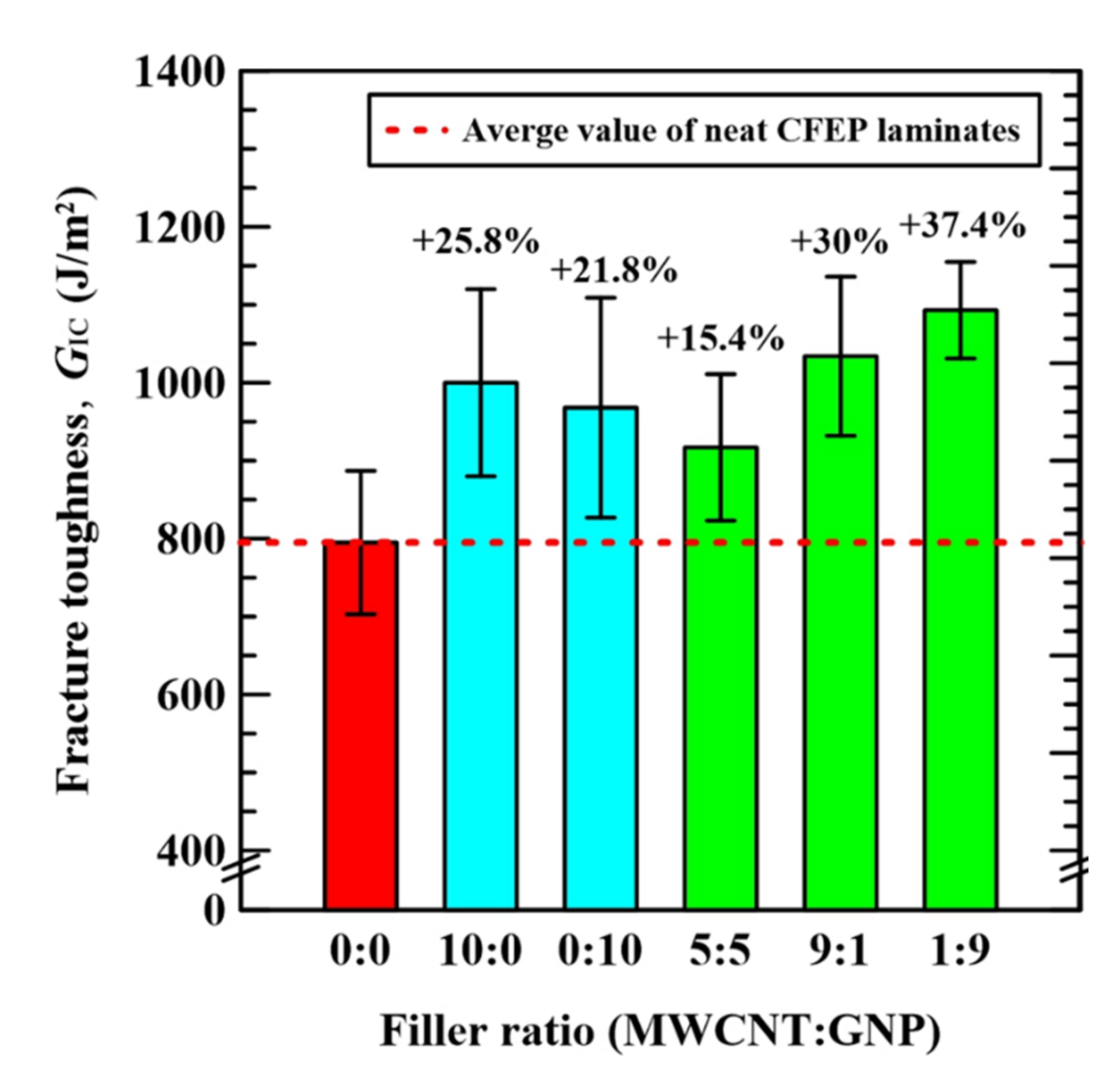
| Nanofiller Ratio MWCNT:GNP | Neat Epoxy | 10:0 | 0:10 | 5:5 | 9:1 | 1:9 |
| Mode I fracture toughness GIC(J/m2) | 795 ± 92 | 1000 ± 120 | 968 ± 141 | 917 ± 94 | 1034 ± 102 | 1093 ± 62 |
Publisher’s Note: MDPI stays neutral with regard to jurisdictional claims in published maps and institutional affiliations. |
© 2021 by the authors. Licensee MDPI, Basel, Switzerland. This article is an open access article distributed under the terms and conditions of the Creative Commons Attribution (CC BY) license (https://creativecommons.org/licenses/by/4.0/).
Share and Cite
Jen, Y.-M.; Huang, Y.-C. Improvement in Tensile Quasi-Static and Fatigue Properties of Carbon Fiber-Reinforced Epoxy Laminates with Matrices Modified by Carbon Nanotubes and Graphene Nanoplatelets Hybrid Nanofillers. Nanomaterials 2021, 11, 3459. https://doi.org/10.3390/nano11123459
Jen Y-M, Huang Y-C. Improvement in Tensile Quasi-Static and Fatigue Properties of Carbon Fiber-Reinforced Epoxy Laminates with Matrices Modified by Carbon Nanotubes and Graphene Nanoplatelets Hybrid Nanofillers. Nanomaterials. 2021; 11(12):3459. https://doi.org/10.3390/nano11123459
Chicago/Turabian StyleJen, Yi-Ming, and Yu-Ching Huang. 2021. "Improvement in Tensile Quasi-Static and Fatigue Properties of Carbon Fiber-Reinforced Epoxy Laminates with Matrices Modified by Carbon Nanotubes and Graphene Nanoplatelets Hybrid Nanofillers" Nanomaterials 11, no. 12: 3459. https://doi.org/10.3390/nano11123459
APA StyleJen, Y.-M., & Huang, Y.-C. (2021). Improvement in Tensile Quasi-Static and Fatigue Properties of Carbon Fiber-Reinforced Epoxy Laminates with Matrices Modified by Carbon Nanotubes and Graphene Nanoplatelets Hybrid Nanofillers. Nanomaterials, 11(12), 3459. https://doi.org/10.3390/nano11123459