
Shallow Donor Impurity States with Excitonic Contribution in GaAs/AlGaAs and CdTe/CdSe Truncated Conical Quantum Dots under Applied Magnetic Field

 , , , ,
  , , and
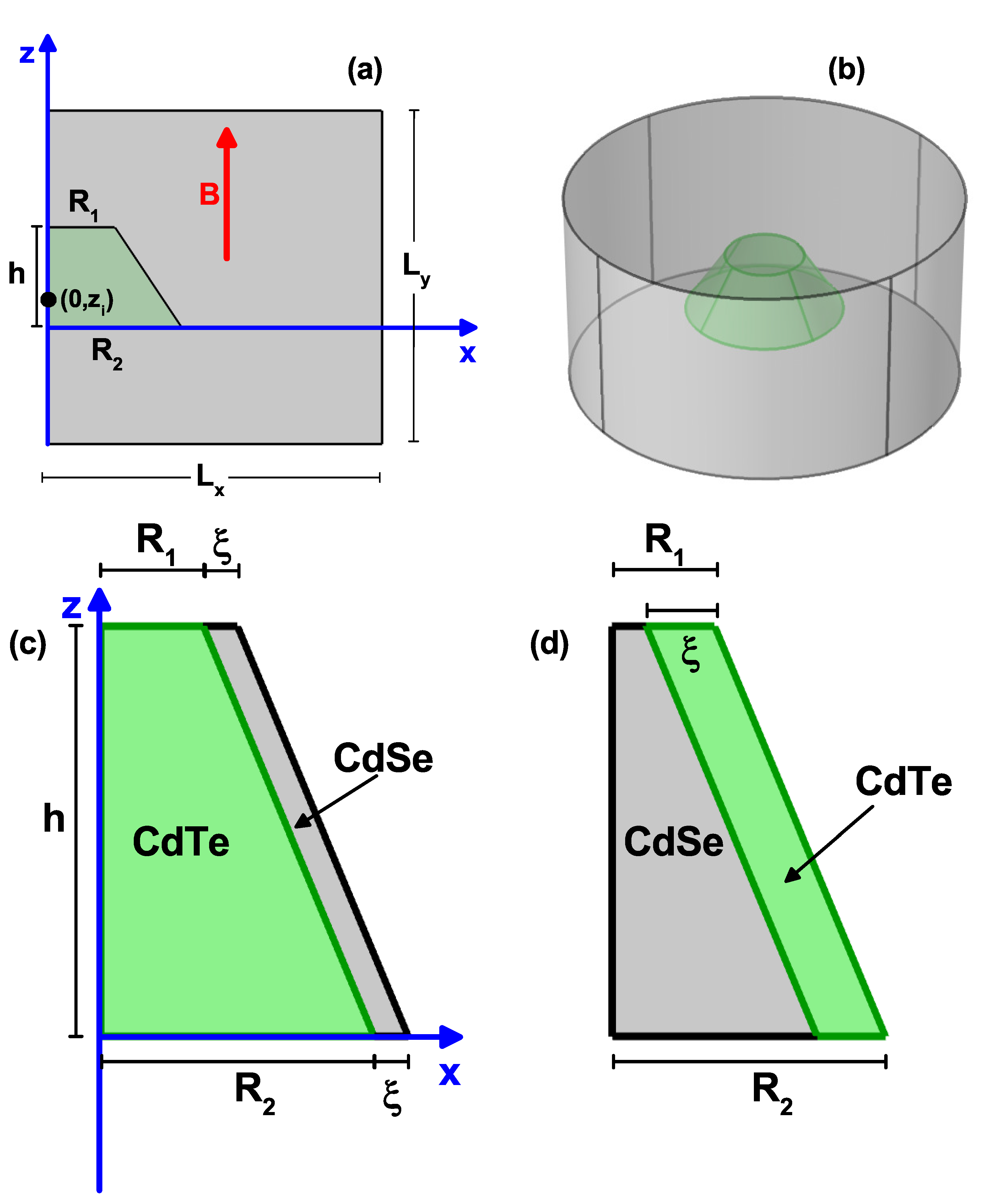
Abstract
:1. Introduction
2. Theoretical Model
3. Results and Discussion
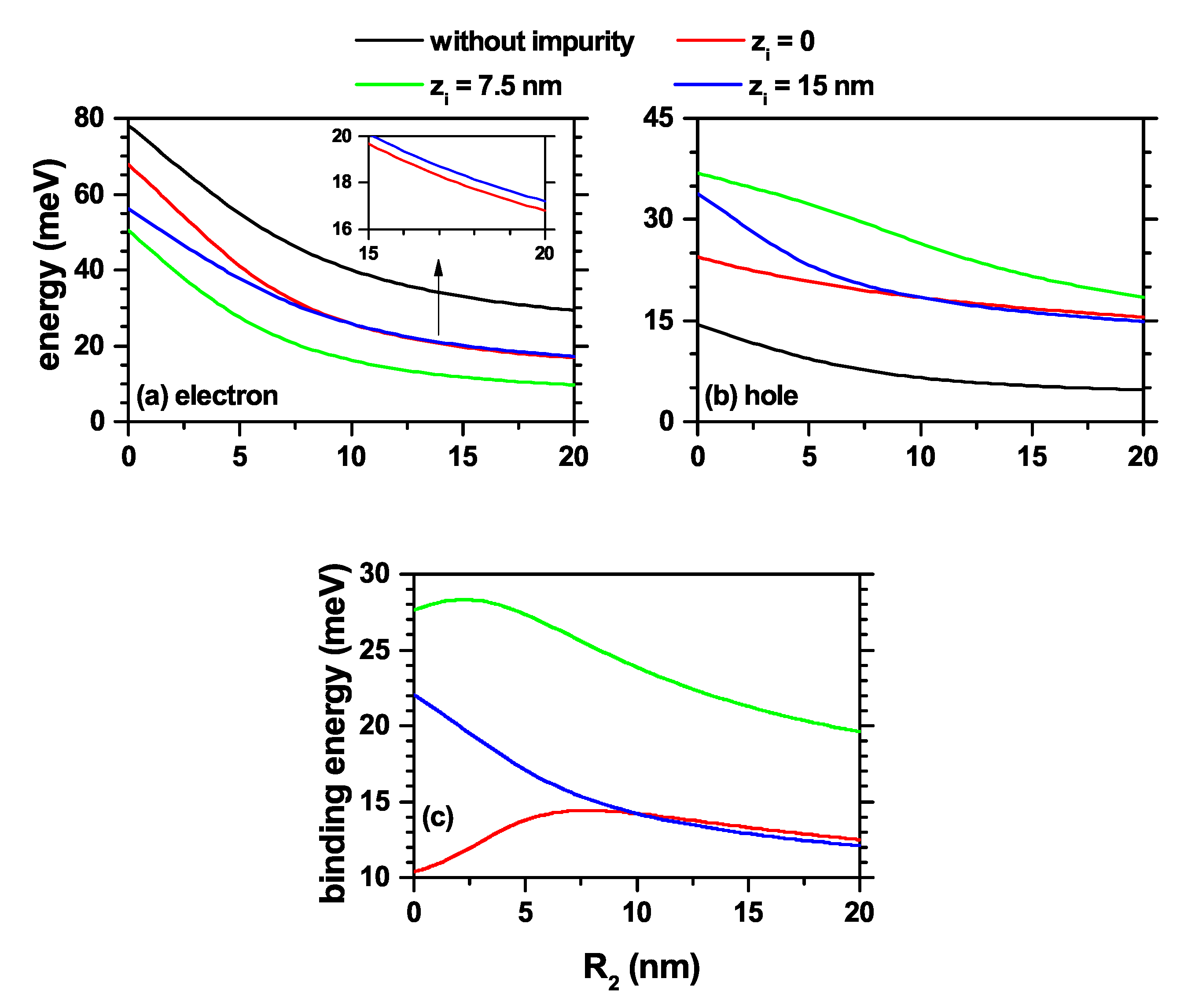
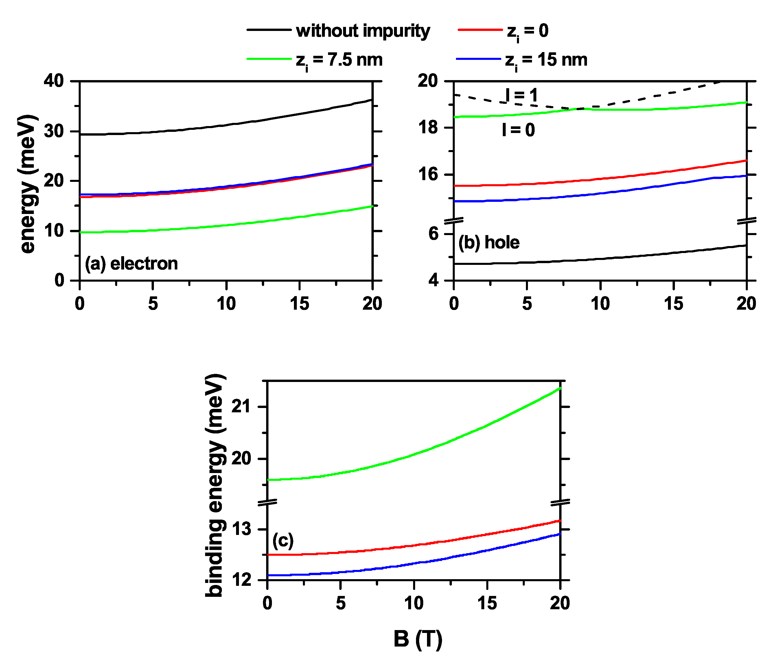
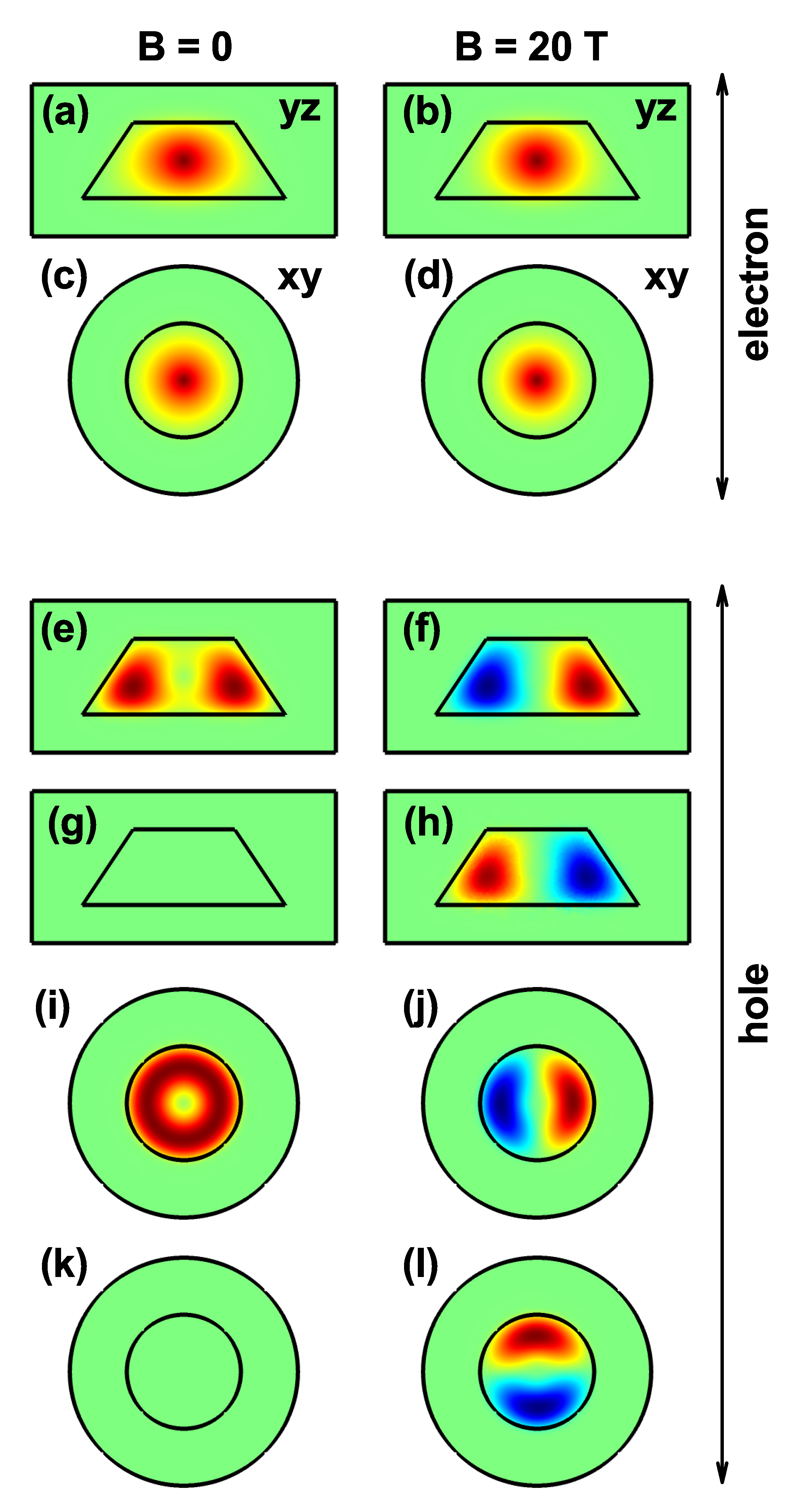
3.1. Electron and Hole Spectra in GaAs-AlGaAs Truncated Conical Quantum Dot under Donor Impurity and Static Magnetic Field Effects
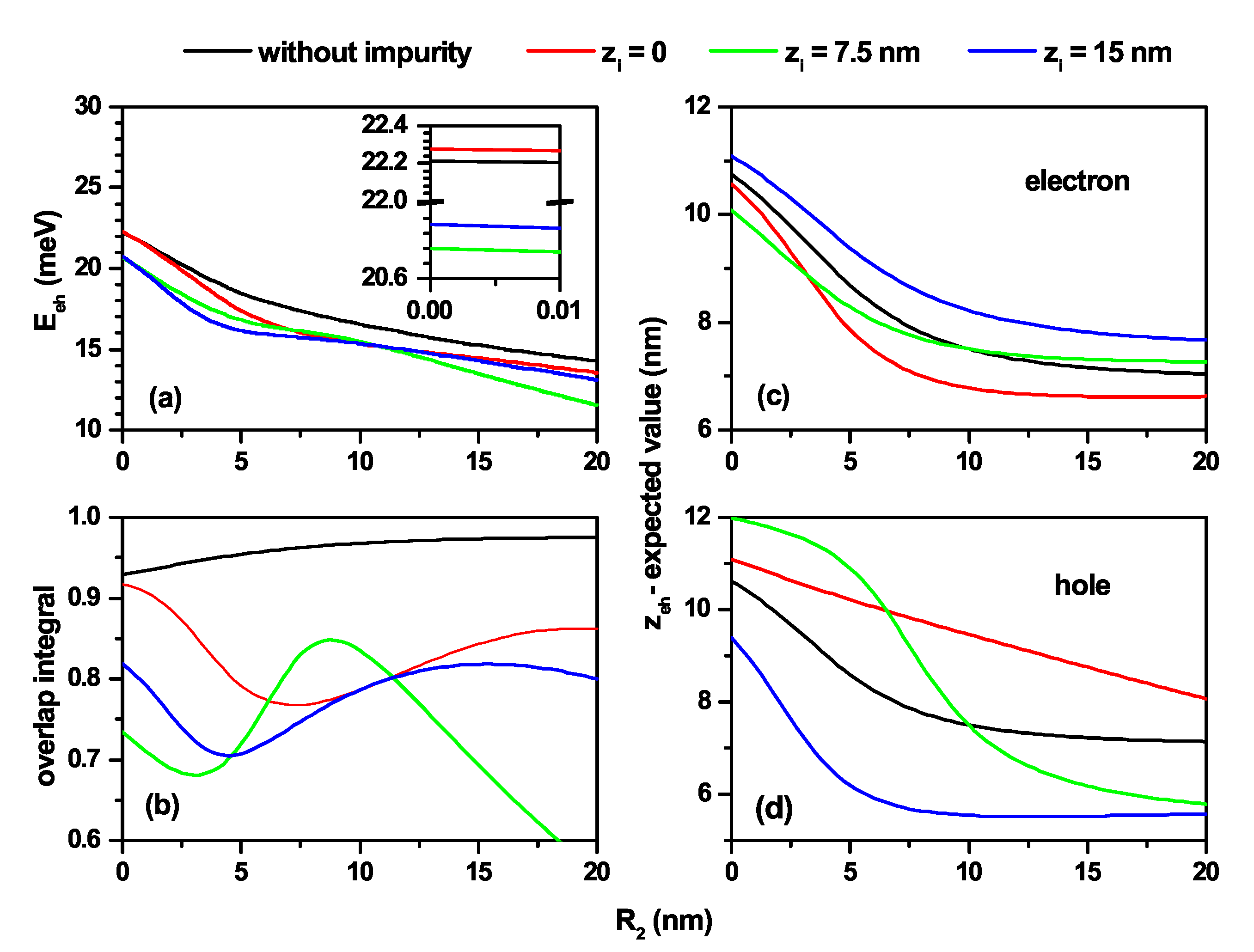
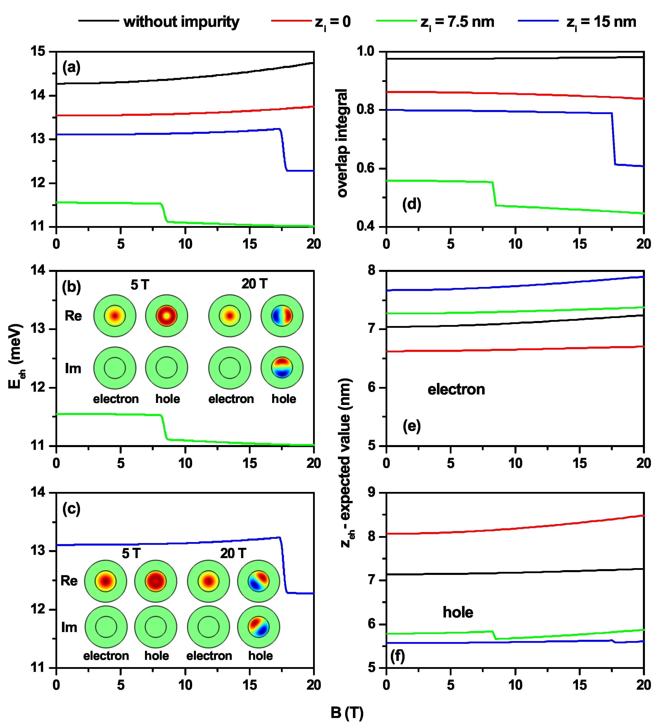
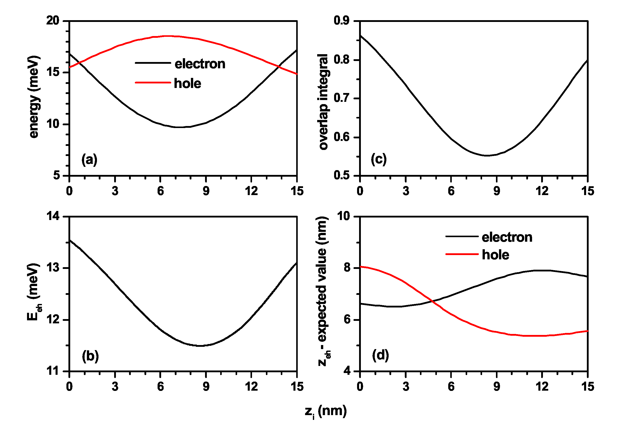
3.2. Exciton States in GaAs-AlGaAs Truncated Conical Quantum Dot under Impurity and Static Magnetic Field
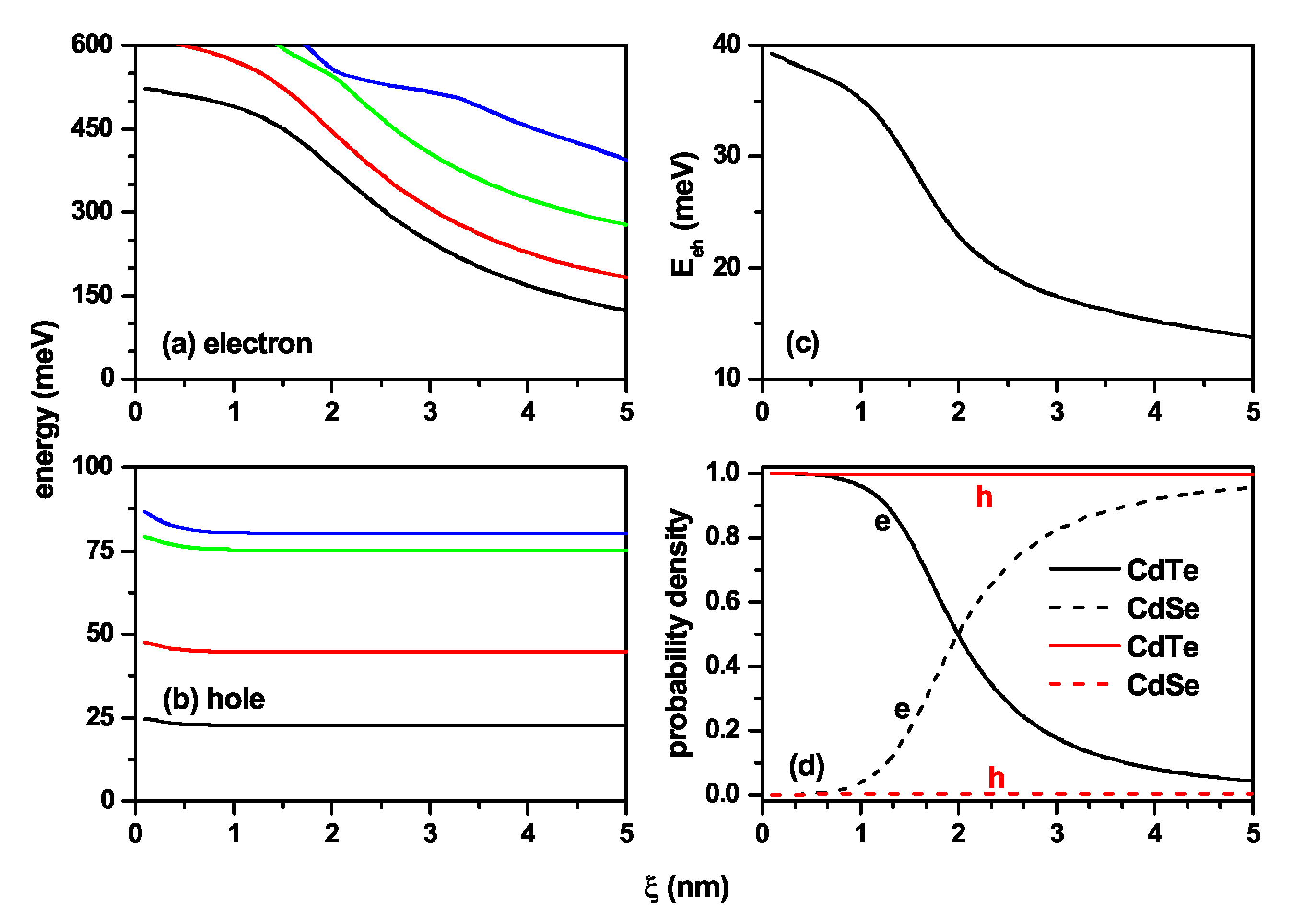
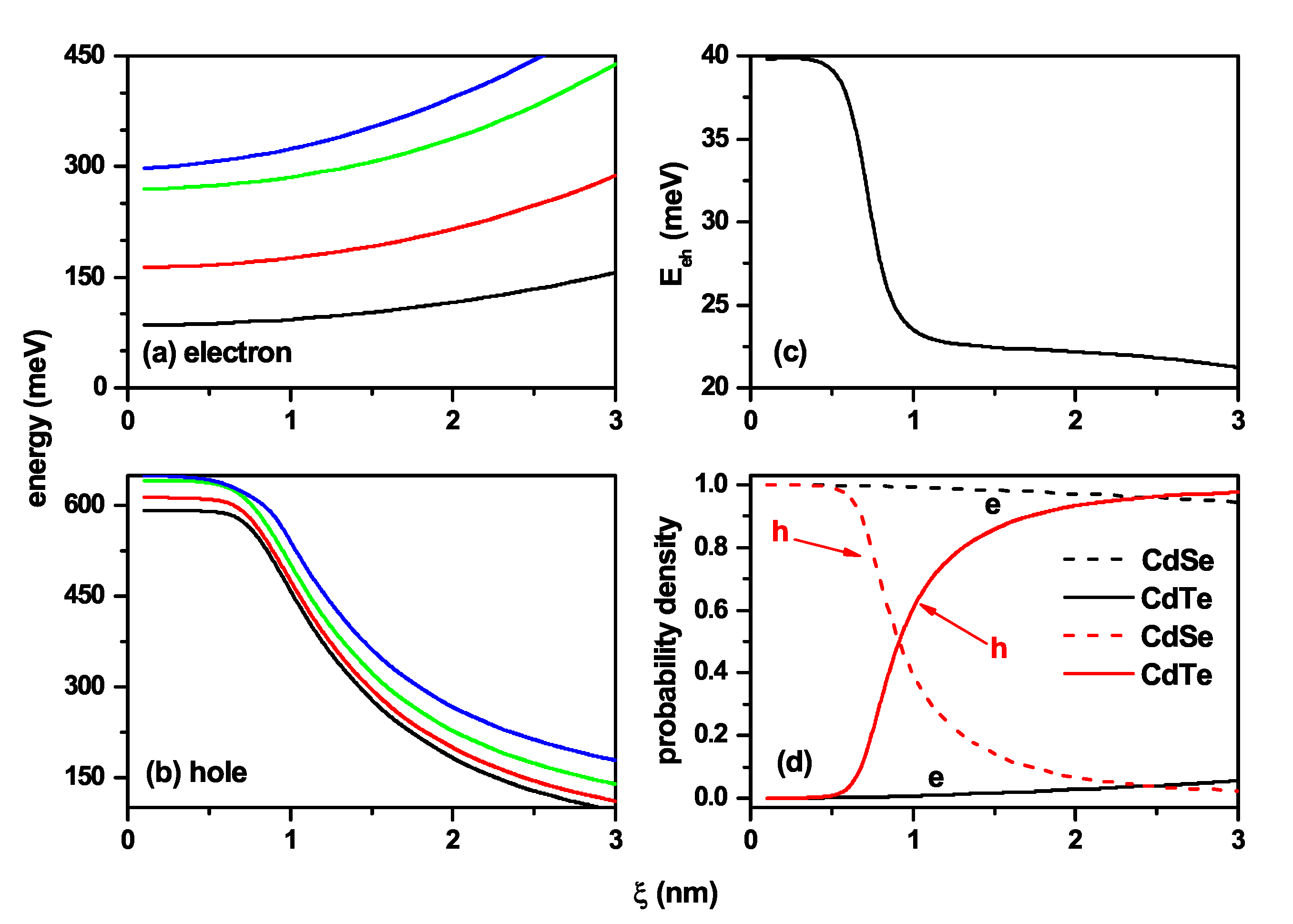
3.3. Tuning from Direct to Indirect Exciton in Truncated Conical CdSe–CdTe Core–Shell Quantum Dots
4. Conclusions
Author Contributions
Funding
Institutional Review Board Statement
Informed Consent Statement
Data Availability Statement
Acknowledgments
Conflicts of Interest
References
- Lorke, A.; Luyken, R.J. Many-particle ground states and excitations in nanometer-size quantum structures. Physica B 1998, 256–258, 424–430. [Google Scholar] [CrossRef]
- Warburton, R.J.; Schulhauser, C.; Haft, D.; Schäflein, C.; Karrai, K.; Garcia, J.M.; Schoenfeld, W.; Petroff, P.M. Giant permanent dipole moments of excitons in semiconductor nanostructures. Phys. Rev. B 2002, 65, 113303. [Google Scholar] [CrossRef] [Green Version]
- Alén, B.; Martínez-Pastor, J.; Granados, D.; García, J.M. Continuum and discrete excitation spectrum of single quantum rings. Phys. Rev. B 2005, 72, 155331. [Google Scholar] [CrossRef] [Green Version]
- Kuroda, T.; Mano, T.; Ochiai, T.; Sanguinetti, S.; Sakoda, K.; Kido, G.; Koguchi, N. Optical transitions in quantum ring complexes. Phys. Rev. B 2005, 72, 205301. [Google Scholar] [CrossRef] [Green Version]
- Bastard, G. Hydrogenic impurity states in a quantum well: A simple model. Phys. Rev. B 1981, 24, 4714–4722. [Google Scholar] [CrossRef]
- Greene, R.L.; Bajaj, K.K. Effect of magnetic field on the energy levels of a hydrogenic impurity center in GaAs/Ga1-xAlxAs quantum-well structures. Phys. Rev. B 1985, 31, 913–918. [Google Scholar] [CrossRef]
- Greene, R.L.; Bajaj, K.K. Energy levels of hydrogenic impurity states in GaAs-Ga1-xAlxAs quantum well structures. Solid State Commun. 1983, 45, 825–829. [Google Scholar] [CrossRef]
- Branis, S.V.; Li, G.; Bajaj, K.K. Hydrogenic impurities in quantum wires in the presence of a magnetic field. Phys. Rev. B 1993, 47, 1316–1323. [Google Scholar] [CrossRef]
- Zhu, J.-L. Exact solutions for hydrogenic donor states in a spherically rectangular quantum well. Phys. Rev. B 1989, 39, 8780–8783. [Google Scholar] [CrossRef] [PubMed]
- Ribeiro, F.J.; Latgé, A. Impurities in a quantum dot: A comparative study. Phys. Rev. B 1994, 50, 4913–4916. [Google Scholar] [CrossRef]
- Szafran, B.; Adamowski, J.; Bednarek, S. Electron—Electron correlation in quantum dots. Physica E 1999, 5, 185–195. [Google Scholar] [CrossRef]
- Zhou, W.; Coleman, J.J. Semiconductor quantum dots. Curr. Opin. Solid St. M 2016, 20, 352–360. [Google Scholar] [CrossRef]
- Gaponenko, S.V.; Demir, H.V. Applied Nanophotonics; Cambridge University Press: Cambridge, UK, 2019; p. 433. [Google Scholar]
- Porras-Montenegro, N.; Pérez-Merchancano, S.T.; Latgé, A. Binding energies and density of impurity states in spherical GaAs-(Ga,Al)As quantum dots. J. Appl. Phys. 1993, 74, 7624–7626. [Google Scholar] [CrossRef]
- Le Goff, S.; Stébé, B. Influence of longitudinal and lateral confinements on excitons in cylindrical quantum dots of semiconductors. Phys. Rev. B 1993, 47, 1383–1391. [Google Scholar] [CrossRef]
- Cristea, M.; Niculescu, E.C.; Truşcǎ, C.R. Optical non-linearities associated to hydrogenic impurities in InAs/GaAs self-assembled quantum dots under applied electric fields. Philos. Mag. 2017, 97, 3343–3360. [Google Scholar] [CrossRef]
- Niculescu, E.C.; Stan, C.; Cristea, M.; Truscǎ, C. Magnetic-field dependence of the impurity states in a dome-shaped quantum dot. Chem. Phys. 2017, 493, 32–41. [Google Scholar] [CrossRef]
- Medvid, A. Nano-cones formed on a surface of semiconductors by laser radiation: Technology, model and properties. In Nanowires Science and Technology; Intech: Vukovar, Croatia, 2010; pp. 61–82. [Google Scholar]
- Nedzinskas, R.; Karpus, V.; Čechavičius, B.; Kavaliauskas, J.; Valušis, G. Electron energy spectrum in cylindrical quantum dots and rods: Approximation of separation of variables. Phys. Scr. 2015, 90, 065801. [Google Scholar] [CrossRef]
- Sil, N.; Daripa, N.; Kapoor, A.; Dey, S.K. Perturbation method for calculating impurity binding energy in an inhomogeneous cylindrical quantum dot with dielectric mismatch. Pramana-J. Phys. 2018, 90, 7. [Google Scholar] [CrossRef]
- Mal, I.; Samajdar, D.P.; John Peter, A. Theoretical studies on band structure and optical gain of GaInAsN/GaAs/GaAs cylindrical quantum dot. Superlattice Microst. 2018, 119, 103–113. [Google Scholar] [CrossRef]
- Lin, H.-M.; Chen, Y.-L.; Yang, J.; Liu, Y.-C.; Yin, K.-M.; Kai, J.-J.; Chen, F.-R.; Chen, L.-C.; Chen, Y.-F.; Chen, C.-C. Synthesis and of core–shell GaP@GaN and GaN@GaP nanowires. Nano Lett. 2003, 3, 537–541. [Google Scholar] [CrossRef]
- Medvid, A.; Mychko, A.; Strilchyk, O.; Litovchenko, N.; Naseka, Y.; Onufrijevs, P.; Pludonis, A. Exciton quantum confinement effect in nanostructures formed by laser radiation on the surface of CdZnTe ternary compound. Phys. Status Solidi C 2009, 6, 209–212. [Google Scholar] [CrossRef]
- Maher, O.; Témim, K.; Jlassi, B.; Balti, J.; Jaziri, S. Effect of the In (Ga) inter-diffusion on the optical properties in InAs/GaAs annealed quantum dots. J. Phys. Conf. Ser. 2010, 245, 012066. [Google Scholar] [CrossRef]
- Medvid, A.; Onufrijevs, P.; Mychko, A. Properties of nanocones formed on a surface of semiconductors by laser radiation: Quantum confinement effect of electrons, phonons, and excitons. Nanoscale Res. Lett. 2011, 6, 582. [Google Scholar] [CrossRef] [Green Version]
- Nadj-Perge, S.; Frolov, S.M.; Bakkers, E.P.A.M.; Kouwenhoven, L.P. Spin-orbit qubit in a semiconductor nanowire. Nature 2010, 468, 1084–1087. [Google Scholar] [CrossRef] [PubMed]
- Tatebayashi, J.; Kako, S.; Ho, J.; Ota, Y.; Iwamoto, S.; Arakawa, Y. Roomtemperature lasing in a single nanowire with quantum dots. Nat. Photonics 2015, 9, 501–505. [Google Scholar] [CrossRef]
- Svensson, J.; Dey, A.W.; Jacobsson, D.; Wernersson, L.-E. III–V nanowire complementary metal-oxide semiconductor transistors monolithically integrated on Si. Nano Lett. 2015, 15, 7898–7904. [Google Scholar] [CrossRef] [Green Version]
- Heedt, S.; Prost, W.; Schubert, J.; Grützmacher, D.; Schäpers, T. Ballistic transport and exchange interaction in InAs nanowire quantum point contacts. Nano Lett. 2016, 16, 3116–3123. [Google Scholar] [CrossRef]
- Diedenhofen, S.L.; Janssen, O.T.A.; Grzela, G.; Bakkers, E.P.A.M.; Gómez Rivas, J. Strong geometrical dependence of the absorption of light in arrays of semiconductor nanowires. ACS Nano 2011, 5, 2316–2323. [Google Scholar] [CrossRef]
- Khordad, R.; Bahramiyan, H. Study of impurity position effect in pyramid and cone like quantum dots. Eur. Phys. J. Appl. Phys. 2014, 67, 20402. [Google Scholar] [CrossRef]
- Hayrapetyan, D.B.; Kazaryan, E.M.; Sarkisyan, H.A. Magneto-absorption in conical quantum dot ensemble: Possible applications for QD LED. Opt. Commun. 2016, 371, 138–143. [Google Scholar] [CrossRef]
- Delerue, C.; Lannoo, M. Nanostructures Theory and Modelling; Springer: Berlin/Heidelberg, Germany, 2004; p. 304. [Google Scholar]
- Wang, Y.; Wang, J.; Guo, H. Magnetoconductance of a stadium-shaped quantum dot: A finite-element-method approach. Phys. Rev. B 1994, 49, 1928–1934. [Google Scholar] [CrossRef] [PubMed]
- Zhou, W.-M.; Wang, C.-Y.; Chen, Y.-H.; Wang, Z.-G. Finite element analysis of stress and strain distributions in InAs/GaAs quantum dots. Chin. Phys. 2006, 15, 1315–1319. [Google Scholar]
- Satori, H.; Sali, A. The finite element simulation for the shallow impurity in quantum dots. Physica E 2013, 48, 171–175. [Google Scholar] [CrossRef]
- Jurczak, G.; Dłużewski, P. Finite element modelling of threading dislocation effect on polar GaN/AlN quantum dot. Physica E 2018, 95, 11–15. [Google Scholar] [CrossRef]
- Solaimani, M. Binding energy and diamagnetic susceptibility of donor impurities in quantum dots with different geometries and potentials. Mater. Sci. Eng. B-Adv. 2020, 262, 114694. [Google Scholar] [CrossRef]
- Khaledian, S.; Nalaini, F.; Mehrbakhsh, M.; Abdoli, M.; Salehi Zahabi, S. Applications of novel quantum dots derived from layered materials in cancer cell imaging. FlatChem 2021, 27, 100246. [Google Scholar] [CrossRef]
- Nxele, S.R.; Nyokong, T. The effects of the composition and structure of quantum dots combined with cobalt phthalocyanine and an aptamer on the electrochemical detection of prostate specific antigen. Dyes Pigment. 2021, 192, 109407. [Google Scholar] [CrossRef]
- Gidwani, B.; Sahu, V.; Shukla, S.S.; Pandey, R.; Joshi, V.; Jain, V.K.; Vyas, A. Quantum dots: Prospectives, toxicity, advances and applications. J. Drug Deliv. Sci. Tec. 2021, 61, 102308. [Google Scholar] [CrossRef]
- Kumar, P. Semiconductor (CdSe and CdTe)quantum dot: Synthesis, properties and applications. Mater. Today-Proc. 2021. [Google Scholar] [CrossRef]
- Xu, G.; Zeng, S.; Zhang, B.; Swihart, M.T.; Yong, K.-T.; Prasad, P.N. New Generation Cadmium-Free Quantum Dots for Biophotonics and Nanomedicine. Chem. Rev. 2016, 116, 12234–12327. [Google Scholar] [CrossRef] [PubMed]
- Porras-Montenegro, N.; Duque, C.A.; Reyes-Gómez, E.; Oliveira, L.E. Effects of hydrostatic pressure on the electron g‖ factor and g-factor anisotropy in GaAs-(Ga,Al)As quantum wells under magnetic fields. J. Phys. Condens. Matter 2008, 20, 465220. [Google Scholar] [CrossRef] [PubMed]
- Porras-Montenegro, N.; Raigoza, N.; Reyes-Gómez, E.; Duque, C.A.; Oliveira, L.E. Effects of hydrostatic pressure on the conduction electron g-factor in GaAs-Ga1-xAlxAs quantum wells. Phys. Status Solidi B 2009, 246, 648–651. [Google Scholar] [CrossRef]
- Heyn, C.; Radu, A.; Vinasco, J.A.; Laroze, D.; Restrepo, R.L.; Tulupenko, V.; Hieu, N.N.; Phuc, H.V.; Mora-Ramos, M.E.; Ojeda, J.H.; et al. Exciton states in conical quantum dots under applied electric and magnetic fields. Opt. Laser Technol. 2021, 139, 106953. [Google Scholar] [CrossRef]
- Graf, A.; Sonnenberg, D.; Paulava, V.; Schliwa, A.; Heyn, C.; Hansen, W. Excitonic states in GaAs quantum dots fabricated by local droplet etching. Phys. Rev. B 2014, 89, 115314. [Google Scholar] [CrossRef]
- López, S.Y.; Porras-Montenegro, N.; Duque, C.A. Excitons in coupled quantum dots: Hydrostatic pressure and electric field effects. Phys. Status Solidi B 2009, 246, 630–634. [Google Scholar] [CrossRef] [Green Version]
- López, S.Y.; Mora-Ramos, M.E.; Duque, C.A. Photoluminescence energy transitions in GaAs-Ga1-xAlxAs double quantum wells: Electric and magnetic fields and hydrostatic pressure effects. Physica B 2009, 404, 5181–5184. [Google Scholar] [CrossRef]
- Mora-Ramos, M.E.; Barseghyan, M.G.; Duque, C.A. Excitons in cylindrical GaAs Pöschl-Teller quantum dots: Hydrostatic pressure and temperature effects. Physica E 2010, 43, 338–344. [Google Scholar] [CrossRef]
- Mora-Ramos, M.E.; Barseghyan, M.G.; Duque, C.A. Excitons in a cylindrical GaAs Pöschl-Teller quantum dot. Phys. Status Solidi B 2011, 248, 1412–1419. [Google Scholar] [CrossRef]
- Vinasco, J.A.; Radu, A.; Kasapoglu, E.; Restrepo, R.L.; Morales, A.L.; Feddi, E.; Mora-Ramos, M.E.; Duque, C.A. Effects of geometry on the electronic properties of semiconductor elliptical quantum rings. Sci. Rep. 2018, 8, 13299. [Google Scholar] [CrossRef]
- Vinasco, J.A.; Radu, A.; Restrepo, R.L.; Morales, A.L.; Mora-Ramos, M.E.; Duque, C.A. Magnetic field effects on intraband transitions in elliptically polarized laser-dressed quantum rings. Opt. Mater. 2019, 91, 309–320. [Google Scholar] [CrossRef]
- COMSOL. Multiphysics; v. 5.4; COMSOL AB: Stockholm, Sweden, 2012. [Google Scholar]
- COMSOL. Multiphysics Reference Guide; COMSOL AB: Stockholm, Sweden, 2012. [Google Scholar]
- COMSOL. Multiphysics Users Guide; COMSOL AB: Stockholm, Sweden, 2012. [Google Scholar]
- Heyn, C.; Duque, C.A. Donor impurity related optical and electronic properties of cylindrical GaAs-AlxGa1-xAs quantum dots under tilted electric and magnetic fields. Sci. Rep. 2020, 10, 9155. [Google Scholar] [CrossRef] [PubMed]
- Suresh, S.; Arunseshan, C. Dielectric Properties of Cadmium Selenide (CdSe) Nanoparticles synthesized by solvothermal method. Appl. Nanosci. 2014, 4, 179–184. [Google Scholar] [CrossRef] [Green Version]


Publisher’s Note: MDPI stays neutral with regard to jurisdictional claims in published maps and institutional affiliations. |
© 2021 by the authors. Licensee MDPI, Basel, Switzerland. This article is an open access article distributed under the terms and conditions of the Creative Commons Attribution (CC BY) license (https://creativecommons.org/licenses/by/4.0/).
Share and Cite
Pulgar-Velásquez, L.; Sierra-Ortega, J.; Vinasco, J.A.; Laroze, D.; Radu, A.; Kasapoglu, E.; Restrepo, R.L.; Gil-Corrales, J.A.; Morales, A.L.; Duque, C.A. Shallow Donor Impurity States with Excitonic Contribution in GaAs/AlGaAs and CdTe/CdSe Truncated Conical Quantum Dots under Applied Magnetic Field. Nanomaterials 2021, 11, 2832. https://doi.org/10.3390/nano11112832
Pulgar-Velásquez L, Sierra-Ortega J, Vinasco JA, Laroze D, Radu A, Kasapoglu E, Restrepo RL, Gil-Corrales JA, Morales AL, Duque CA. Shallow Donor Impurity States with Excitonic Contribution in GaAs/AlGaAs and CdTe/CdSe Truncated Conical Quantum Dots under Applied Magnetic Field. Nanomaterials. 2021; 11(11):2832. https://doi.org/10.3390/nano11112832
Chicago/Turabian StylePulgar-Velásquez, Lorenz, José Sierra-Ortega, Juan A. Vinasco, David Laroze, Adrian Radu, Esin Kasapoglu, Ricardo L. Restrepo, John A. Gil-Corrales, Alvaro L. Morales, and Carlos A. Duque. 2021. "Shallow Donor Impurity States with Excitonic Contribution in GaAs/AlGaAs and CdTe/CdSe Truncated Conical Quantum Dots under Applied Magnetic Field" Nanomaterials 11, no. 11: 2832. https://doi.org/10.3390/nano11112832