
Features of the Synthesis of the Dispersed TiC Phase with Nickel Nanostructures on the Surface to Create an Aluminum-Based Metal Composite


 ,
,
Abstract
:1. Introduction
2. Materials and Methods
2.1. Materials
2.2. Mechanism of Formation of Ni Nanocoating on the TiC Particles Surface (TiC/Ni)
2.3. Powder Compaction
- Aluminum ASP-50 was pre-sieved on a vibrating screen VP-30T using a sieve with a cell size of 80 microns. A larger fraction was rejected.
- A suspension of Al (100 g) in 500 mL of isopropyl alcohol was shaken, filtered, dried in air, finally dried under vacuum at room temperature.
2.4. Characterization
2.5. Mechanical Tests, Tests for Uniaxial Tension
3. Results and Discussions
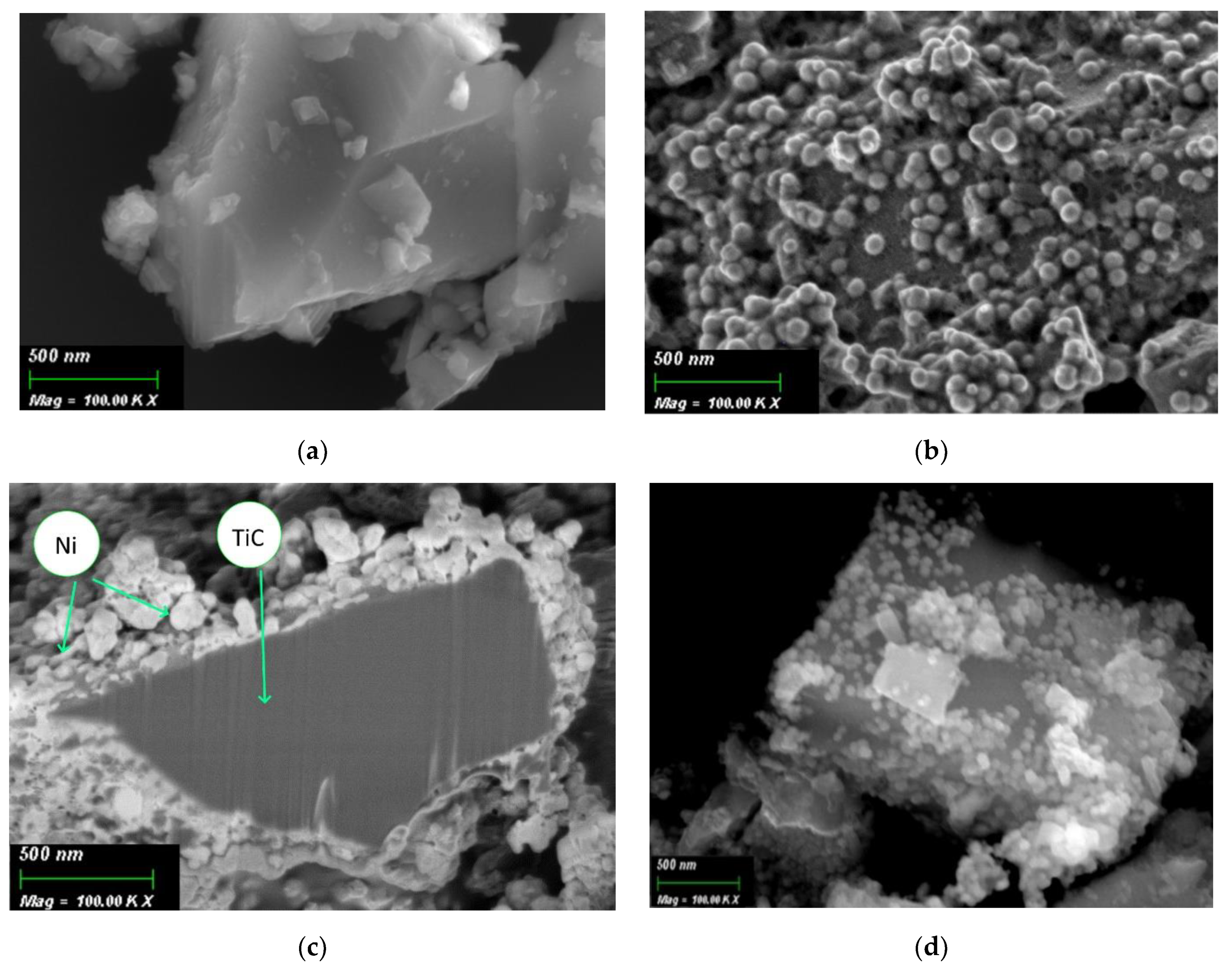
3.1. SEM and EDX
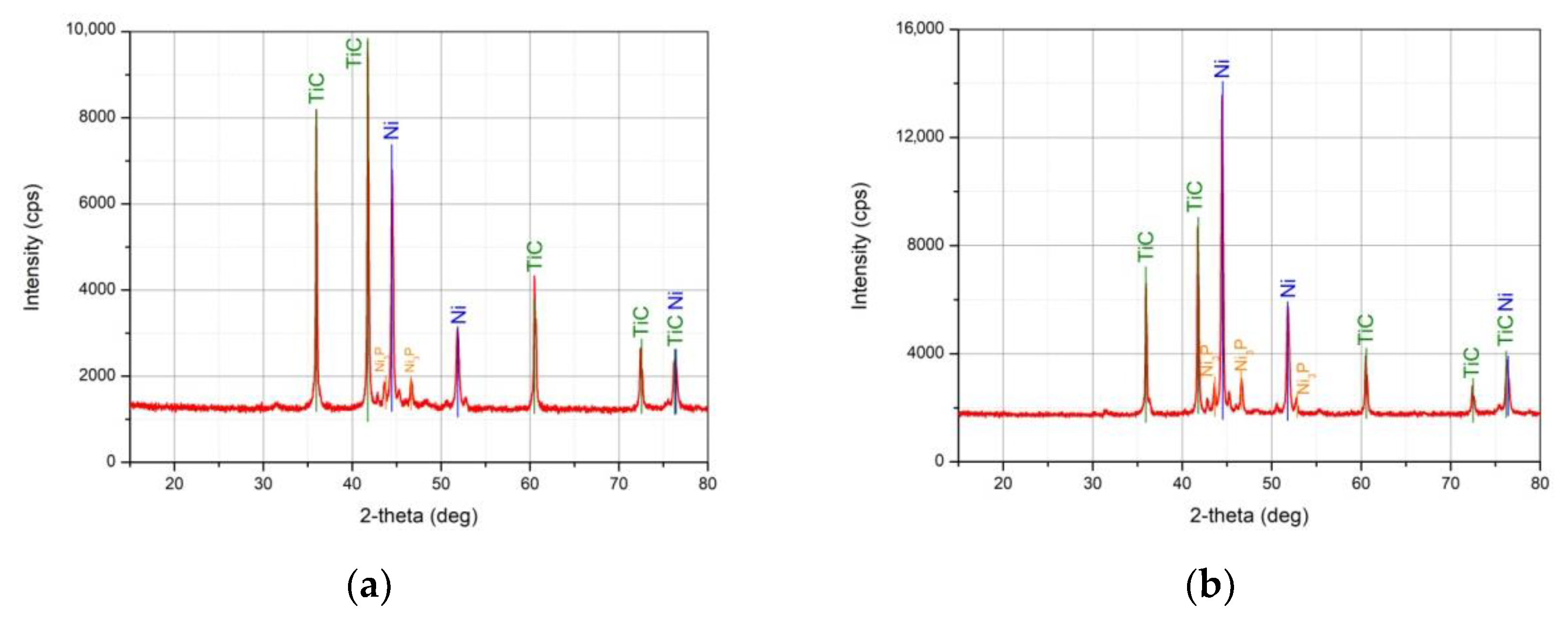
3.2. XRD Analysis
3.3. Mechanical Uniaxial Stretching Tests
4. Conclusions
Author Contributions
Funding
Data Availability Statement
Acknowledgments
Conflicts of Interest
References
- Matthews, F.L.; Rawlings, R.D. Composite Materials: Engineering and Science, 1st ed.; Woodhead Publishing: Cambridge, UK, 1999; 480p. [Google Scholar]
- Zemtsova, E.G.; Monin, A.V.; Smirnov, V.M.; Semenov, B.N.; Morozov, N.F. Synthesis of ceramic composites using three-dimensional nanostructuring (reinforcement) of alumina matrix with TiN and SiC nanostructures and study of their mechanical properties. Phys. Mesomech. 2017, 20, 438–446. [Google Scholar] [CrossRef]
- Zemtsova, E.G.; Yurchuk, D.V.; Sidorov, Y.V.; Semenov, B.N.; Morozov, N.F.; Smirnov, V.M. Synthesis of metallic composite based on iron frame and SiC nanostructures and its strength properties. Mater. Phys. Mech. 2020, 46, 122–131. [Google Scholar]
- Bakshi, S.R.; Lahiri, D.; Agarwal, A. Carbon Nanotube Reinforced Metal Matrix Composites—A Review. Int. Mater. Rev. 2010, 55, 41–64. [Google Scholar] [CrossRef]
- Suryanarayana, C.; Al-Aqeeli, N. Mechanically alloyed nanocomposites. Prog. Mater. Sci. 2013, 58, 383–502. [Google Scholar] [CrossRef]
- Gu, D.D.; Shen, Y.F. Direct Laser Sintered WC-10Co/Cu Nanocomposites. Appl. Surf. Sci. 2008, 254, 3971–3978. [Google Scholar] [CrossRef]
- Viswanathan, V.; Laha, T.; Balani, K.; Agarwal, A.; Seal, S. Challenges and advances in nanocomposite processing techniques. Mater. Sci. Eng. R 2006, 54, 121–285. [Google Scholar] [CrossRef]
- Hashim, J. The production of cast metal matrix composite by a modified stir casting method. J. Teknol. 2012, 35, 9–20. [Google Scholar] [CrossRef] [Green Version]
- Gopalakrishnan, S.; Murugan, N. Production and wear characterisation of AA 6061 matrix titanium carbide particulate reinforced composite by enhanced stir casting method. Compos. Part B-Eng. 2012, 43, 302–308. [Google Scholar] [CrossRef]
- Gopalakrishnan, S.; Murugan, N. Production of aluminium matrix TiCp composite by modified stir casting process. World. J. Eng. 2009, 6, 7–13. [Google Scholar]
- Ranjan, R.; Singh, A.R.K. Al MMC Reinforced with Al. In Innovation in Materials Science and Engineering, 1st ed.; Chattopadhyay, J., Singh, R., Prakash, O., Eds.; Springer: Singapore, 2019; Volume 2, pp. 219–224. [Google Scholar]
- Nassar, A.E.; Nassar, E.E. Properties of aluminum matrix Nano composites prepared by powder metallurgy processing. J. King Saud Univ. Eng. Sci. 2017, 29, 295–299. [Google Scholar] [CrossRef] [Green Version]
- Bodukuri, A.K.; Eswaraiah, K.; Rajendar, K.; Sampath, V. Fabrication of Al–SiC–B4C metal matrix composite by powder metallurgy technique and evaluating mechanical properties. Perspect. Sci. 2016, 8, 428–431. [Google Scholar] [CrossRef] [Green Version]
- Ataee-Esfahani, H.; Vaezi, M.R.; Nikzad, L.; Yazdani, B.; Sadrnezhaad, S.K. Influence of SiC nanoparticles and saccharin on the structure and properties of electrodeposited Ni–Fe/SiC nanocomposite coatings. J. Alloys Compd. 2009, 484, 540–544. [Google Scholar] [CrossRef]
- Tolochko, O.V.; Koltsova, T.S.; Bobrynina, E.V.; Rudskoy, A.I.; Zemtsova, E.G.; Kirichenko, S.O.; Smirnov, V.M. Conditions for production of composite material based on aluminum and carbon nanofibers and its physic-mechanical properties. Nanomaterials 2019, 9, 550. [Google Scholar] [CrossRef] [Green Version]
- Abolkassem, S.A.; Elkady, O.A.; Elsayed, A.H.; Hussein, W.A.; Yehya, H.M. Effect of consolidation techniques on the properties of Al matrix composite reinforced with nano Ni-coated SiC. Results Phys. 2018, 9, 1102–1111. [Google Scholar] [CrossRef]
- Feng, Y.; Chen, C.; Wang, R.; Wang, X. Microstructures and mechanical properties of Ni-coated SiC particles reinforced AZ61 alloy composites. Trans. Nonferr. Metal. Soc. China 2019, 29, 1854–1863. [Google Scholar] [CrossRef]
- Ramesh, C.S.; Srinivas, C.K.; Channabasappa, B.H. Abrasive wear behaviour of laser sintered iron–SiC composites. Wear 2009, 267, 1777–1783. [Google Scholar] [CrossRef]
- Zou, G.; Cao, M.; Lin, H.; Jin, H.; Kang, Y.; Chen, Y. Nickel layer deposition on SiC nanoparticles by simple electroless plating and its dielectric behaviors. Powder Technol. 2006, 168, 84–88. [Google Scholar] [CrossRef]
- Kang, Y.-Q.; Cao, M.-S.; Shi, X.-L.; Hou, Z.-L. The enhanced dielectric from basalt fibers/nickel core-shell structures synthesized by electroless plating. Surf. Coat. Technol. 2007, 201, 7201–7206. [Google Scholar] [CrossRef]
- Xu, H.; Kang, Y.-Q.; Zhang, L.; Jin, H.-B.; Wen, B.; Wen, B.-L.; Yuan, J.; Cao, M.-S. Deposition behavior and mechanism of Ni nanoparticles on surface of SiC particles in solution systems. Chin. Phys. Lett. 2010, 27, 058103–058104. [Google Scholar] [CrossRef]
- Zhang, J.-S. (Ed.) Creep of Second Phase Particles Strengthened Materials. In High Temperature Deformation and Fracture of Materials; Woodhead Publishing: Cambridge, UK, 2007; pp. 83–101. [Google Scholar]
- Vo, N.Q.; Liebscher, C.H.; Rawlings, M.J.S.; Asta, M.; Dunand, D.C. Creep properties and microstructure of a precipitation-strengthened ferritic Fe-Al-Ni-Cr alloy. Acta Mater. 2016, 71, 89–99. [Google Scholar] [CrossRef]
- Sun, L.; Simm, T.H.; Martin, T.L.; McAdam, S.; Galvin, D.R.; Perkins, K.M.; Bagot, P.A.J.; Moody, M.P.; Ooi, S.W.; Hill, P.; et al. A novel ultra-high strength maraging steel with balanced ductility and creep resistance achieved by nanoscale β-NiAl and Laves phase precipitates. Acta Mater. 2016, 149, 285–301. [Google Scholar] [CrossRef] [Green Version]
- Xu, S.; McDowell, D.L.; Beyerlein, I.J. Sequential obstacle interactions with dislocations in a planar array. Acta Mater. 2019, 174, 160–172. [Google Scholar] [CrossRef]


| Solution | Component | Concentration |
|---|---|---|
| SnCl2 solution | SnCl2 | 10 g/L |
| HCl conc. | 30 mL/L | |
| PdCl2 solution | PdCl2 | 0.25 g/L |
| HCl conc. | 3 mL/L | |
| NiCl2 solution | NiCl2 | 45 g/L |
| NH4Cl | 50 g/L | |
| Na citrate | 100 g/L | |
| NH3 conc. | until pH 8.5 | |
| TiC | 5 g/L |
| Cycles Number | Sample Code | TiC Weight | The Mass of the Sample after Drying | Weight Gain, % |
|---|---|---|---|---|
| 1 | TiC/Ni-1 | 1.96 g | 3.23 g | 64.8% |
| 3 | TiC/Ni-3 | 1.90 g | 3.82 g | 101.3% |
| Average Content | ||||
|---|---|---|---|---|
| Element | Intensity for Initial TiC | Average Content for Initial TiC, at.% | Intensity for TiC/Ni-1 | Average Content for TiC/Ni-1, at.% |
| Ti | 213.14 | 94.73 | 175.59 | 68.45 |
| W | 6.70 | 3.27 | 4.22 | 1.64 |
| Ni | - | - | 64.25 | 25.05 |
| Fe | 1.17 | 0.53 | 0.14 | 0.05 |
| Co | 1.66 | 0.77 | - | - |
| Nb | 0.66 | 0.32 | 0.57 | 0.22 |
| Sn | - | - | 7.26 | 2.83 |
| Pd | - | - | 2.93 | 1.64 |
| P | - | - | 1.10 | 0.43 |
| Others | 0.55 | 0.24 | 1.03 | 0.40 |
| Average Content, at.% | |||
|---|---|---|---|
| Element | Initial TiC | TiC/Ni-1 | TiC/Ni-3 |
| Ti | 52.02 | 32.70 | 49.17 |
| P | - | 5.67 | - |
| Ni | - | 13.65 | 13.30 |
| Number | Sample Composition | Ultimate Strength (σ), MPa | Density Ratio (exp/calc), % | Yield Strength, MPa | Relative Elongation (S), % |
|---|---|---|---|---|---|
| 1 | Al | 76 ± 2.0 | 98.35 | 31.2 ± 0.2 | 26.20 |
| 2 | Al + 5% TiC | 106 ± 2.0 | 98.47 | 45.0 ± 0.2 | 13.20 |
| 3 | Al + 5% TiC/Ni | 116 ± 2.0 | 98.13 | 38.0 ± 0.2 | 7.50 |
Publisher’s Note: MDPI stays neutral with regard to jurisdictional claims in published maps and institutional affiliations. |
© 2021 by the authors. Licensee MDPI, Basel, Switzerland. This article is an open access article distributed under the terms and conditions of the Creative Commons Attribution (CC BY) license (https://creativecommons.org/licenses/by/4.0/).
Share and Cite
Zemtsova, E.G.; Yurchuk, D.V.; Morozov, P.E.; Korusenko, P.M.; Kudymov, V.K.; Smirnov, V.M. Features of the Synthesis of the Dispersed TiC Phase with Nickel Nanostructures on the Surface to Create an Aluminum-Based Metal Composite. Nanomaterials 2021, 11, 2499. https://doi.org/10.3390/nano11102499
Zemtsova EG, Yurchuk DV, Morozov PE, Korusenko PM, Kudymov VK, Smirnov VM. Features of the Synthesis of the Dispersed TiC Phase with Nickel Nanostructures on the Surface to Create an Aluminum-Based Metal Composite. Nanomaterials. 2021; 11(10):2499. https://doi.org/10.3390/nano11102499
Chicago/Turabian StyleZemtsova, Elena G., Denis V. Yurchuk, Pavel E. Morozov, Petr M. Korusenko, Vladimir K. Kudymov, and Vladimir M. Smirnov. 2021. "Features of the Synthesis of the Dispersed TiC Phase with Nickel Nanostructures on the Surface to Create an Aluminum-Based Metal Composite" Nanomaterials 11, no. 10: 2499. https://doi.org/10.3390/nano11102499
APA StyleZemtsova, E. G., Yurchuk, D. V., Morozov, P. E., Korusenko, P. M., Kudymov, V. K., & Smirnov, V. M. (2021). Features of the Synthesis of the Dispersed TiC Phase with Nickel Nanostructures on the Surface to Create an Aluminum-Based Metal Composite. Nanomaterials, 11(10), 2499. https://doi.org/10.3390/nano11102499