Article

Fabrication and Characterization of Double- and Single-Clamped CuO Nanowire Based Nanoelectromechanical Switches

1
Institute of Chemical Physics, University of Latvia, 1 Jelgavas Street, LV-1004 Riga, Latvia
2
Faculty of Chemistry, University of Latvia, 1 Jelgavas Street, LV-1004 Riga, Latvia
*
Author to whom correspondence should be addressed.
Nanomaterials 2021, 11(1), 117; https://doi.org/10.3390/nano11010117
Submission received: 30 November 2020 / Revised: 22 December 2020 / Accepted: 1 January 2021 / Published: 6 January 2021

Abstract

:
Electrostatically actuated nanoelectromechanical (NEM) switches hold promise for operation with sharply defined ON/OFF states, high ON/OFF current ratio, low OFF state power consumption, and a compact design. The present challenge for the development of nanoelectromechanical system (NEMS) technology is fabrication of single nanowire based NEM switches. In this work, we demonstrate the first application of CuO nanowires as NEM switch active elements. We develop bottom-up and top-down approaches for NEM switch fabrication, such as CuO nanowire synthesis, lithography, etching, dielectrophoretic alignment of nanowires on electrodes, and nanomanipulations for building devices that are suitable for scalable production. Theoretical modelling finds the device geometry that is necessary for volatile switching. The modelling results are validated by constructing gateless double-clamped and single-clamped devices on-chip that show robust and repeatable switching. The proposed design and fabrication route enable the scalable integration of bottom-up synthesized nanowires in NEMS.

1. Introduction

The nanoelectromechanical (NEM) switch stands out as an energy-efficient candidate for logic and memory applications, due to two most important characteristics of mechanical switching: well-defined ON and OFF states and zero OFF state current [1,2,3], thus making it the ideal switch. Because atomic diffusion does not significantly impact the performance of these devices, mechanical switches can withstand a higher temperature than their conventional electronic-only semiconductor counterparts [2,4]. Despite the promising characteristics, the scalable fabrication and reliability of NEM switches is still an ongoing effort from both the characterization and technological perspectives [1,2].
The operation and properties of NEM switches can be experimentally explored by two approaches: using nanomanipulations in situ inside transmission [5,6,7,8,9] or scanning [10,11,12] electron microscopes and as micro-/nanofabricated on-chip devices [13,14,15,16,17,18].
The ability of rapid adjustment of the NEM switch configuration is an advantage of the in situ electron microscopy approach while using nanomanipulations [10,11,12], which allows for exploring different working regimes without the repetitive nanofabrication of multiple devices. Novel methods for NEM switch operation have been previously demonstrated in situ, such as decreasing of the switch-ON and switch-OFF voltages by using oscillations at resonance frequencies [10,12]. In situ characterization inside TEM and SEM have also allowed for the determination of the mechanical properties of NEM switch active elements, such as Young’s modulus [5,19,20,21], breaking strength [5], and resonant behavior [21,22].
The first on-chip devices were implemented while using carbon nanotube (CNT)-based nanorelays [13], followed by different metals [14,23], semiconductors [17,18], and, recently, also TiN ceramics [15] and Cu [16]. Most efforts in the fabrication of NEM switches have focused on the top-down approach, integrating the fabrication of the active element in a complex process flow [4,14,15,24]. However, this constrains the available materials and design architectures that are compatible with lithographic processing. The alternative use of bottom-up synthesized quasi-one-dimensional (1D) nanostructures (nanotubes, nanowires) [10,12,25] taps into an exciting field of various materials with different properties and versatile functionality for application in NEM switches.
Among the bottom-up synthesized 1D structures, CNTs are, by far, the most popular choice for NEM switches, due to their high Young’s modulus [25] and high resonance frequencies [26]. However, CNT-based NEM switches suffer from ablation during contact and they require additional electrode coating (e.g., diamond-like-carbon) to enhance contact reliability [27]. Single-crystalline and defect-free semiconductor nanowires [28], such as Si [17], Ge [8,29], and GeSn [12], have also been explored as potential candidate materials and demonstrated reliable operation at voltages up to 40–50 V. This enables their applications for high-voltage and low-current devices. CuO is a narrow band gap semiconductor that can be thermally oxidized in order to produce nanowires. It has been recently shown that CuO nanowires exhibit mechanical and electrical properties that are suitable for NEM switch applications [30,31]. High yield, controllable morphology of the as-grown nanowires and the low cost and simplicity of the method motivate the investigation of CuO nanowire use in NEM switches.
One of the greatest challenges for NEM switch fabrication while using bottom-up methods is the precise positioning of the active elements relative to the metal electrodes. The assembly of bottom-up synthesized active elements for NEM switches can be realized by spin-coating of the nanowire suspension [32], using dry mechanical transfer [33], dielectrophoresis (DEP) [34,35,36], and mechanical manipulation [37,38]. Dry mechanical transfer by pressing the substrate with nanowires against the chip with electrodes is fast and cost-effective, but it cannot ensure the nanowire positioning in predefined locations. Mechanical manipulation allows for precise alignment, but it is very time consuming. The DEP technique that is used in the present study increases the device fabrication throughput significantly by careful tuning of process parameters. The suspended length of the nanowire, number of nanowires, and their alignment direction on the electrodes can be efficiently controlled by DEP parameters (frequency, voltage, time), hydrodynamic forces, distance between the electrodes, and their shape and size [34,35].
To the best of our knowledge, integration of bottom-up synthesized semiconductor nanowires in NEM switches on-chip and their operation has not yet been tested. Here, we develop a theoretical model for optimizing the device parameters for volatile NEM switch operation. The model is used to calculate the switch-ON voltages for different NEM switch dimensions. Based on the acquired theoretical results, the full fabrication process of single- and double-clamped NEM switch is performed: (1) a scalable cost effective synthesis of CuO nanowires [30] for use as the NEM switch active elements; (2) fabrication of micropatterned device electrodes; and (3) dielectrophoresis [33] to align the nanowires on the electrodes. The developed NEM switches are tested for volatile switching in order to validate the theoretical results for both double-clamped and single-clamped devices.

2. Materials and Methods

Copper oxide (CuO) nanowires were synthesized by thermal oxidation of a Cu foil (99.9% purity, 25 μm thickness; Goodfellow GmbH, Hamburg, Germany) in a tube furnace (GSL-1100X, MTI Corporation, Richmond, CA, USA) at 500 °C for 3.5 h in ambient air, as reported in [30,39]. Figure 1a shows the typical process flow for the fabrication of electrodes and alignment of the as-synthesized nanowires. For microelectrode fabrication, AZ 1505 photoresist (Microchemicals GmbH, Ulm, Germany) was spin coated on a silicon substrate with thermal silicon dioxide (Microchemicals GmbH, Ulm, Germany) and then patterned using maskless optical lithography direct write system (Heidelberg µPG 101 Micro Pattern Generator, Heidelberg Instruments Mikrotechnik GmbH, Heidelberg, Germany) with a 375 nm laser source by the following procedure. Si substrates with 1000 nm thick thermal SiO2 were cleaned, and then a pattern was defined in a first photoresist layer. After post-bake of the photoresist, the exposed SiO2 was etched with a commercially available buffered oxide etch (BOE 7:1 with Surfactant; Microchemicals GmbH, Ulm, Germany) (Figure 1(a1)) in order to define the distance between the active element and the electrode. 10 nm Cr adhesion layer/70 nm Au layer (Kurt J. Lesker Company, Jefferson Hills, PA, USA) was thermally evaporated into the etched trenches (Figure 1(a2)) to obtain actuation electrodes. After lift-off, the second layer was aligned and patterned while using metal evaporation and lift-off (Figure 1(a3)) in order to define DEP electrodes. Nanowires were assembled on microelectrodes while using dielectrophoretic alignment (Figure 1(a4)) to yield final devices with nanowires that were suspended over a gold electrode (Figure 1(a5)).
To remove the nanowires from the oxidized Cu foil, the sample was placed in isopropyl alcohol and then ultrasonicated for 3 s. For DEP alignment, the as-fabricated chips were immersed in a nanowire-isopropanol suspension, applying AC signal with frequency of 50 kHz [33]. A floating electrode DEP configuration [40,41] was employed, which consisted of an array of two opposing electrodes. One electrode was connected to a common line to which the AC signal was applied. The opposite DEP electrode was held at a floating potential. AC ground was connected to the back of the silicon substrate. Separate actuation electrodes were fabricated between pairs of DEP electrodes, so that the voltage bias could be individually applied to each single-nanowire device. This design allowed for decoupling and analyzing single device characteristics from the DEP array without parallel interference from the other devices.
For the alignment of single nanowires in a double-clamped configuration, DEP was performed on 2 µm wide tapered electrodes (Figure 1b,c). In order to increase the yield of suspended nanowires, 20 µm wide electrodes for multiple nanowire DEP alignment in both single-clamped and double-clamped configurations were used (Figure 1d,e). Finally, to avoid nanowire’s stiction by capillary forces to the substrate during drying (Figure 1b), supercritical CO2 drying was carried out to produce suspended nanowires (Figure 1c).
Electrode structure and topography were inspected in a scanning electron microscope (Hitachi FE-SEM S-4800, Hitachi Ltd., Chiyoda, Tokyo, Japan) and atomic force microscope (AFM, MFP-3D, Asylum Research Inc., Santa Barbara, CA, USA) to find suitable devices. Nanowire manipulation (SmarAct 13D nanomanipulations system, SmarAct GmbH, Oldenburg, Germany) inside the SEM with etched sharp gold tips was used in order to remove other nanowires in cases where more than one nanowire was bridging the gap between the electrodes (Figure 1d,e).
The switches were electrically tested ex situ in a custom-built vacuum chamber and in SEM for visual inspection to monitor the structural stability of the switch.
Numerical calculations were carried out using FreeFem++ software (FreeFem++, version 3.5.8, http://www3.freefem.org/).

3. Results and Discussion

3.1. Fabricated CuO Nanowire-Based NEM Switch Configurations

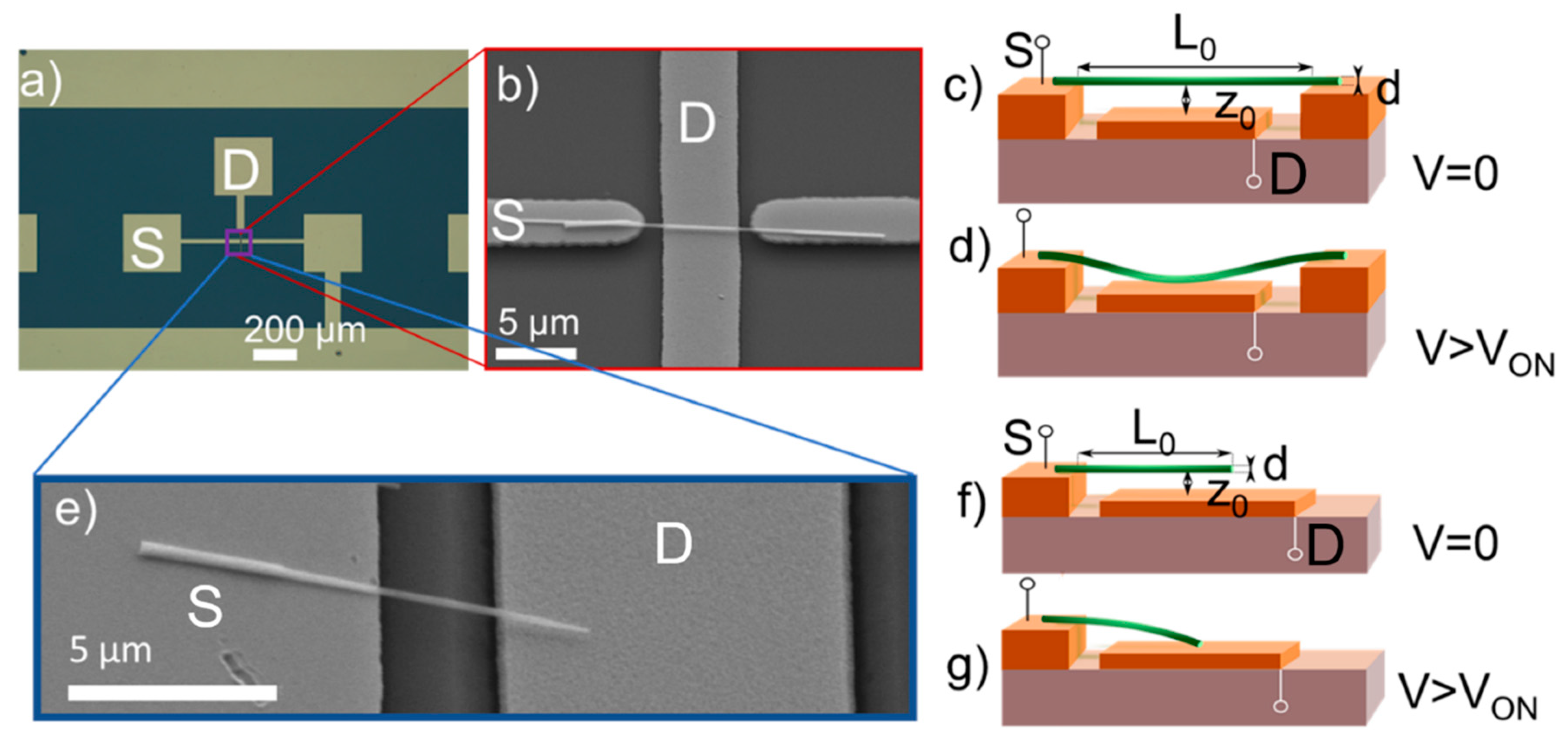
The NEM switches that were fabricated in this work were tested in two different configurations—double-clamped and single-clamped. A single-nanowire double-clamped NEM switch device consists of a nanowire, lying flat on two gold electrodes that serve as both DEP electrodes for alignment and as the grounded switch source terminal (S) (Figure 2a–c). A single-nanowire single-clamped NEM switch has a similar configuration, but with the nanowire only fixed at one end (Figure 2a,e,f). A voltage was applied between the nanowire and lower gold drain electrode (D) to create electrostatic force FE that pulls the nanowire towards D. When the switch-ON voltage VON was reached, a sharp current increase was detected in the circuit (Figure 2d,g). Switch-OFF voltage VOFF was registered when the sum of FE and adhesion force FA in the contact became smaller than elastic tension force Fx in the nanowire and electric current fell to the current noise floor. Switch-OFF occurred at voltages that are lower than those for the switch-ON due to the presence of adhesion force FA.

3.2. NEM Switch Model

We modelled the forces that lead to the switch-ON and switch-OFF events in order to find the optimal operational and design parameters for repeatable NEM switching in a double-clamped setup. The balance between the electrostatic, elastic, and adhesion forces during switching were analyzed by combining the analytic and numerical approaches. The VON was estimated for a range of nanowire diameters, corresponding to the diameter distribution acquired during synthesis. The characteristic range of nanowire diameters for CuO nanowires that were obtained by thermal oxidation in ambient air was approximately 50–200 nm [30] and the minimum distance between the side electrodes in the NEM switch was 6 μm (Figure 2b), which was chosen to ensure a reproducible photolithography process. The mechanical behavior of a double-clamped nanowire with suspended length L0 in response to an external electrostatic force can be described while using the Euler–Bernoulli, Equation (1)
Y ( 4 ) ( ξ ) F x ( ξ ) Y ( 2 ) ( ξ ) F E ( ξ ) = 0 ,   ξ = L L 0
In (1), Y stands for a perpendicular displacement, ξ-for the normalized coordinate along the nanowire, it coincides with the x axis, when the nanowire is not deformed (voltage is not applied), Fx is a tension force, and FE is the linear density of the electrostatic force (Figure 3). The derivatives over the normalized coordinate are represented as upper indices in parentheses. Equation (1) can only be used in the case of small curvatures. The range of distances between the nanowire and the electrode D was chosen in order to ensure that the switch would operate in the small curvature regime. An extra-tension force is induced at the nanowire-electrode contacts due to large curvatures, as described in [42]. It should be mentioned that all of the physical quantities with the dimensionality of length are given in units of the nanowire length, except the nanowire’s suspended length L0 itself.
The linear density of the electrostatic force is given as an integral over the corresponding circular cross section perimeter (2) (Figure 3a).
F E = 4 ε 0 π E L 0 R 3 0 2 π ( d φ d r ) 2 cos α d α
In (2), E stands for the material Young’s modulus, ε0 for the permittivity of vacuum, R for the radius of the nanowire cross section, and φ for the electric potential on the surface. We consider the nanowire as an infinite conducting cylinder. The integration of electric potential over a cross-section perimeter of the nanowire is carried out in order to find the linear density of electrostatic force FE. If the displacement in axial direction is forbidden, then the nanowire will experience tension force Fx. This allows for one to obtain an analytic formula for the electric potential, and, finally, using (2), for the required electrostatic force (3).
F E = 16 E L 0 R 4 V 2 ε 0 z 2 R 2 L n c 2   ,   c = 2 z 2 R 2 ( 1 1 R 2 z 2 ) 1
In (3), z stands for the distance from the cylinder axis to the counter electrode, but V for the applied voltage. To use the obtained Formula (3) in Equation (1), it is necessary to adjust the distance to the counter electrode for each cross section according to the nanowire deflection.
z = z 0 + Y ( ξ )
In (4), z0 represents an initial distance from the nanowire axis to the counter electrode (Figure 3a).
The boundary conditions at the nanowire endpoints determine the tension force Fx in Equation (1). If at least one of the nanowire endpoints can slide in the axial direction, then the Fx is equal to zero. If they are fixed in the axial direction at both ends, then the nanowire will be under tension due to inevitable elongation when it is attracted to the counter electrode, and the tension force Fx can be written as:
F x = 4 R 2 [ 1 0 1 1 ( Y ( 1 ) ( ξ ) ) 2   d ξ ]
In all cases, we considered the nanowire axis direction to be fixed, because of the substantial length of nanowire lying on the electrode. This leads to the following boundary conditions for the perpendicular deflection of the nanowire:
Y ( 0 ) = Y ( 1 ) = Y ( 1 ) ( 0 ) = Y ( 1 ) ( 1 ) = 0
In order to estimate the VON, the problem that is formulated by Equations (1) and (3)–(6) has been numerically solved for a set of increasing values of electric voltage. The threshold voltage, above which the solution could no longer be found (the deformed nanowire intersects the surface of the counter electrode) is reported as VON.
Figure 3b shows the calculated results for VON as a function of nanowire diameter for three different suspended lengths of the nanowires (6, 8, and 8.6 µm) and three different distances between the nanowire and the electrode (120, 180, and 200 nm). The L0 and z0 values were chosen according to the fabrication method. The calculated VON values ranged from 2 to 48 V for NEM switches while using nanowires with diameters in the range of 50–200 nm, which are typical for the used synthesis method. We use the model to find design parameters (L0, and z0) that allow for operating in the VON range below 50 V to prevent burn-out of the nanowire and minimizing the current induced changes in the contact [8,9,22].
For the switch-OFF to occur, the elastic force of the nanowire should exceed the adhesion force in the contact. For finding the adhesion force Fadh, we used the Maugis–Dugdale model adapted by Carpick et al. [43], which has been used for calculations of adhesion force in NEM switch nanowire–electrode contacts and it has shown good agreement with the experimental data [8,9,10].
The restoring elastic force Fel of the nanowire in contact was found when assuming that adhesion force in contact acts as a point force applied in the middle of the beam. The equation that describes such a case is
F e l = 48 E I z L 0 3
where I is the second moment of area of the nanowire and L0–suspended length of the nanowire.
We find that, for example, for a nanowire with a diameter of 150 nm, the optimal suspended nanowire’s length is in the range of 6–8 µm and the initial distance between the nanowire and electrode z0: 120–190 nm. If these conditions are satisfied, then the calculated elastic force (5.2–8.7 × 10⁻⁶ N) in the nanowire exceeds the adhesion force in the contact (4.1–7.9 × 10⁻⁶ N), thus allowing for a successful switch-OFF and repeated operation of the NEM switch.

3.3. Model Comparison with Experimental NEM Switch VON Data

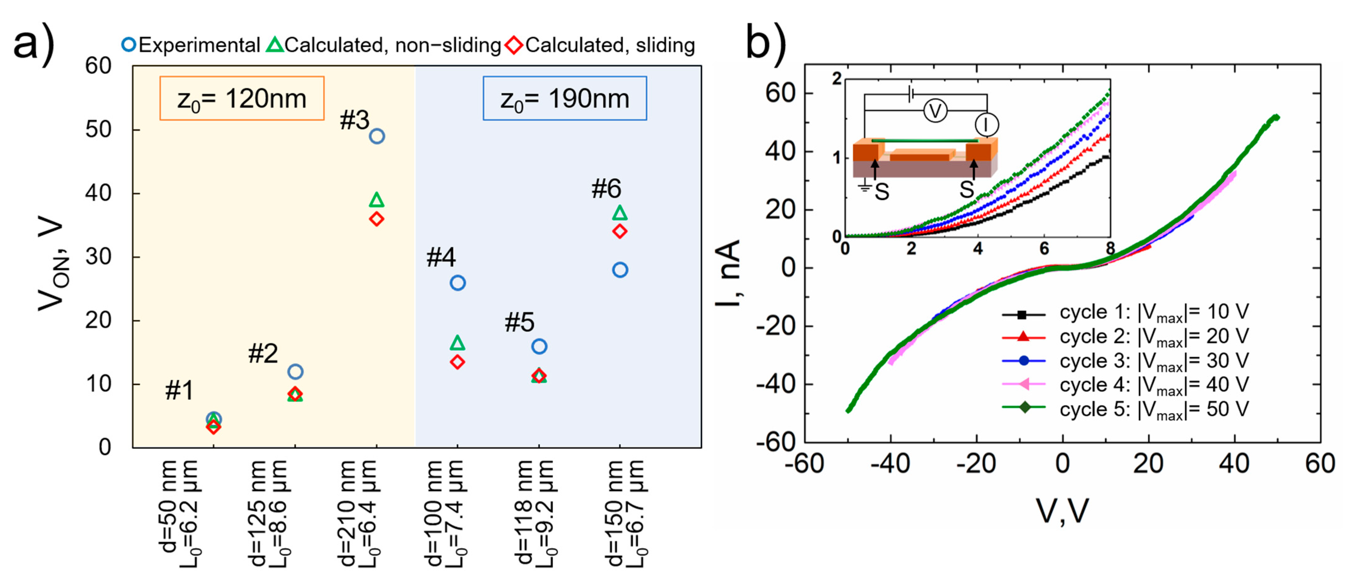
Drawing on the modelling results, we chose distances between the nanowire and electrode to be 120 and 190 nm, suspended nanowire lengths from 6.2 to 9.2 µm to fabricate, and experimentally analyze CuO NEM switches. The resolution of the photolithography limited further downscaling of suspended lengths. The experimentally determined VON values fell within the pre-determined range for the calculated VON values: from 4.5 V for 50 nm thin nanowire up to 49 V for 210 nm thick nanowire for different suspended lengths from 6.2 to 9.2 µm (Figure 4a). Here, all of the fabricated NEM switches are taken into account, including those that only showed one or several operation cycles due to stiction failure. The next section, will consider a typical device that showed volatile operation through many cycles.
As the ends of the nanowire are held to the electrode substrate by adhesion force only, their sliding along the surface of the substrate must be considered. The experimentally determined values for VON were compared with calculated ones considering two different scenarios—with or without nanowire sliding at the contact (Figure 4a). For geometries that were considered in this work sliding during switch-ON can cause a decrease in VON up to 20 % (Figure 4a). The experimentally obtained VON values are higher in all cases. except for one (Figure 4a, device 6), which could indicate sliding in the contact in this single case. It also should be noted that the sliding could be overlooked if the Young’s moduli of the individual nanowires are higher than the average value of 155 GPa [30] used in our calculations. The sliding-induced decrease of the VON in some cases can be observed during repeated cycling and its possible applications will be discussed later. In order to ensure a stable contact between the nanowire and the electrode, an additional fabrication step could be employed, either by lithography or electron beam induced deposition of a metal. However, this increases the complexity of the fabrication process.

3.4. Characterization, Testing and Optimization of Fabricated NEM Switches

In the following section, we describe contact property engineering, operation, and stability of a typical volatile NEM switch device (#6).

3.4.1. Reduction of Nanowire-Electrode Contact Resistance by I–V Cycling

Nanowires that are aligned with DEP may have large contact resistances that can typically be improved by high temperature annealing or argon ion etching [44]. Here, we use an approach that was suggested by Meija et al. [22] employing I–V cycling to improve both contact electrical conductivity and its mechanical strength, which can reduce sliding in the contact. I–V cycling was carried out by applying voltage between the S-S electrodes that support the ends of the nanowire (Figure 4b inset). I–Vs were measured biasing from 0 V to 10 V and symmetrically from 0 V to −10 V with 0.1 V increment. For every next cycle, the absolute value of the maximum voltage |Vmax | was increased with a 10 V step until it reached 50 V (Figure 4b). SEM analysis showed no signs of nanowire degradation, which demonstrated the suitability of CuO active elements for high voltage applications. The symmetric and nonlinear shape of the I–V curves (Figure 4b) suggests that current conduction in these nanowires is a combination of ohmic and space-charge-limited currents, as reported previously [33,45]. The current flowing through the nanowire during I–V cycling induces Joule heating at nanowire-electrode contacts. The I–V characteristics of all NEM switches examined in this work showed an increase of CuO nanowire conductivity with cycling. Figure 4b shows the results for a single NEM switch. The conductivity of the system increased almost two times during 10 cycles. This may be attributed to both enhanced contact [22] and nanowire conductivity [46].

3.4.2. Initial Stages of NEM Switch Operation: VON Stabilization

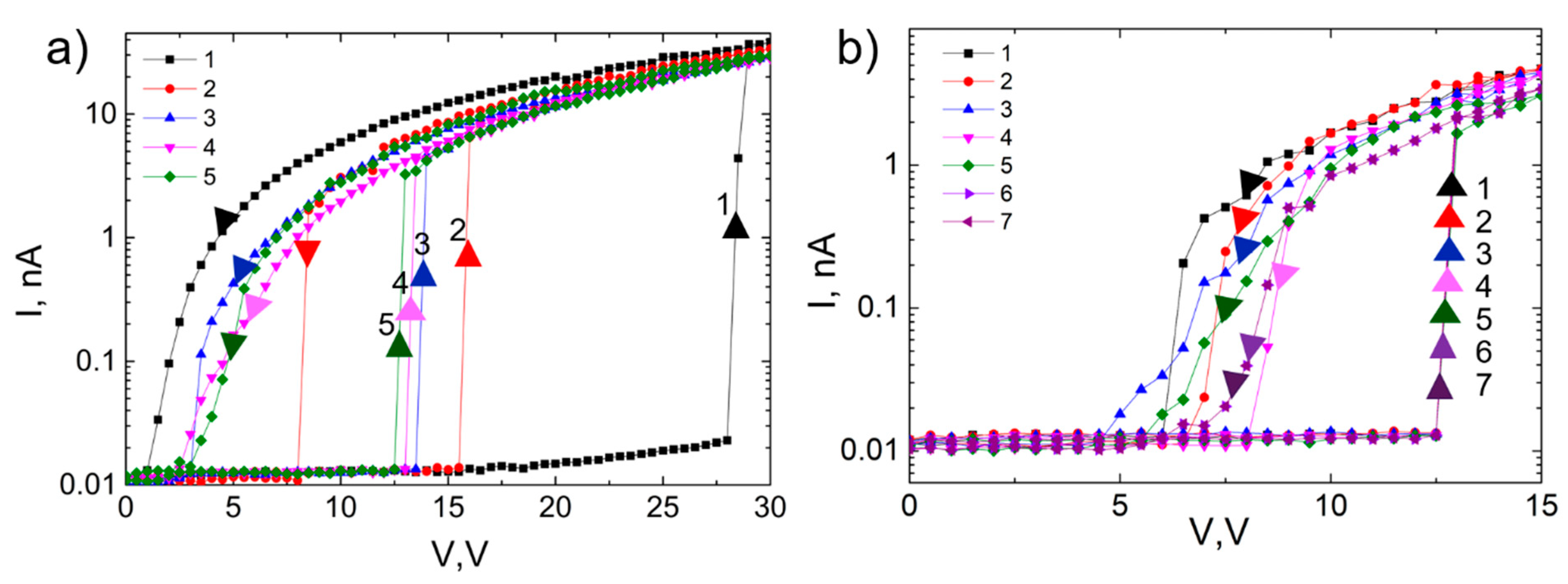
The NEM switch operation was tested by applying the same voltage biasing scheme as during the reduction of contact resistance between the nanowire S and the lower electrode D (Figure 2). This approach is valuable for analyzing the stability of VON and VOFF values. Figure 5a shows the first five cycles of the NEM switch, when it is cycled between 0–30 V. In the first I–V (1), the switch-ON occurs at 28 V and switch-OFF at 1 V. In the second cycle, the VON decreases from 28 V to 15.5 V. During the next three cycles, it gradually decreases towards 12.5 V. As a result of the cycling, the value of VOFF slightly increases from 1 V to 2.5–3.5 V. The initial decrease of VON may be attributed to the nanowire-upper electrode contact modification, which can result in the release of internal mechanical stresses, as well as sliding along the surface. This prevents the nanowire’s return to its original position, and it remains in a slightly deformed shape. In every next voltage cycle, the nanowire slides again until a new stable equilibrium position is found for stable NEM switch operation. A similar step-wise decrease of initial VON value has been reported for the CNT bundle-based NEM switch, where the authors suggest a slipping of the CNT bundle on the support as the possible explanation [47]. This can be contrasted to the gradual voltage decrease observed in [27], which was interpreted as a removal of an outer layer of the nanowire material. The relatively constant ON current level suggests that mechanical effects are responsible for the observed changes in the NEM switch characteristics and there is not much dissipation of electrical power in the nanowire-electrode contact. After five cycles the VON value stabilized and a stable ON-OFF operation of NEM switch followed (Figure 5b), where the switch-ON occurred at 12.5 V and switch-OFF at 4.5–8 V. A decrease of the hysteresis loop may be beneficial for NEM switch operation, as it decreases energy dissipation. The switch-ON is much more abrupt than the switch-OFF, which can be explained by the relatively large contact area of the double-clamped nanowire that needs to detach from the electrode as the voltage is decreased. The differences in the VOFF values between cycles can be explained by variations in contact area. Additionally, the sliding of the nanowire along the contacts can be deliberately employed in order to fine-tune the NEM switch VON to a desired value. When it is reached, the active element can be mechanically fixed while using an additional fabrication step (e.g., by lithography).
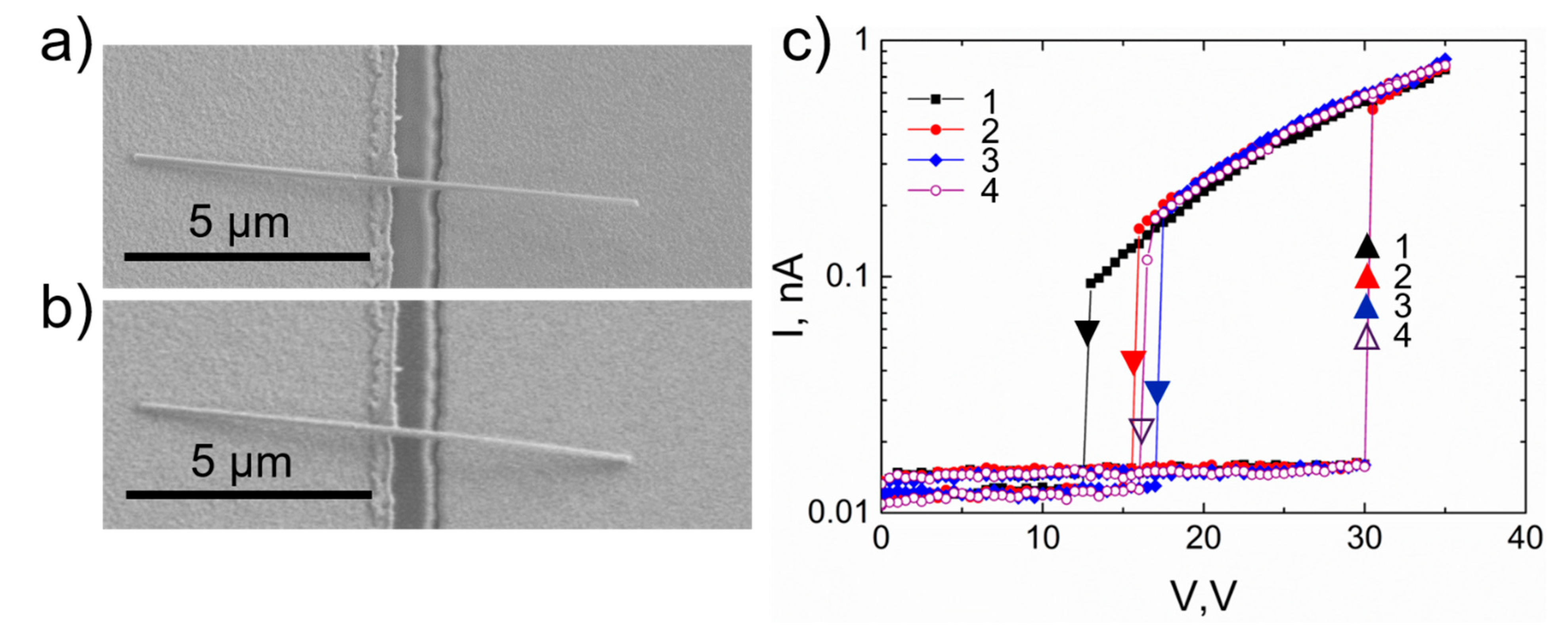
Figure 6a,b shows an example of a single-clamped NEM switch. The geometry of this switch was chosen according to the previous theoretical and experimental work conducted by our group [8,9,12]. VON for this device was 30 V and VOFF 13–17 V. In contrast to the double-clamped case, the transition to ON/OFF states is sharp both for ON and OFF switching, which can be explained by the smaller contact area and faster detachment from the contact electrode. The calculated adhesion force [43] for this single-clamped nanowire (2 × 10⁻⁷ N) is an order of magnitude smaller than for a double-clamped case, which allows for a sharper transition between the ON and OFF states. The smaller adhesion force can be explained by two orders of magnitude smaller effective contact area (78 nm2 for a single-clamped and 7850 nm2 for a double-clamped case).

3.4.3. Cycling of NEM Switch

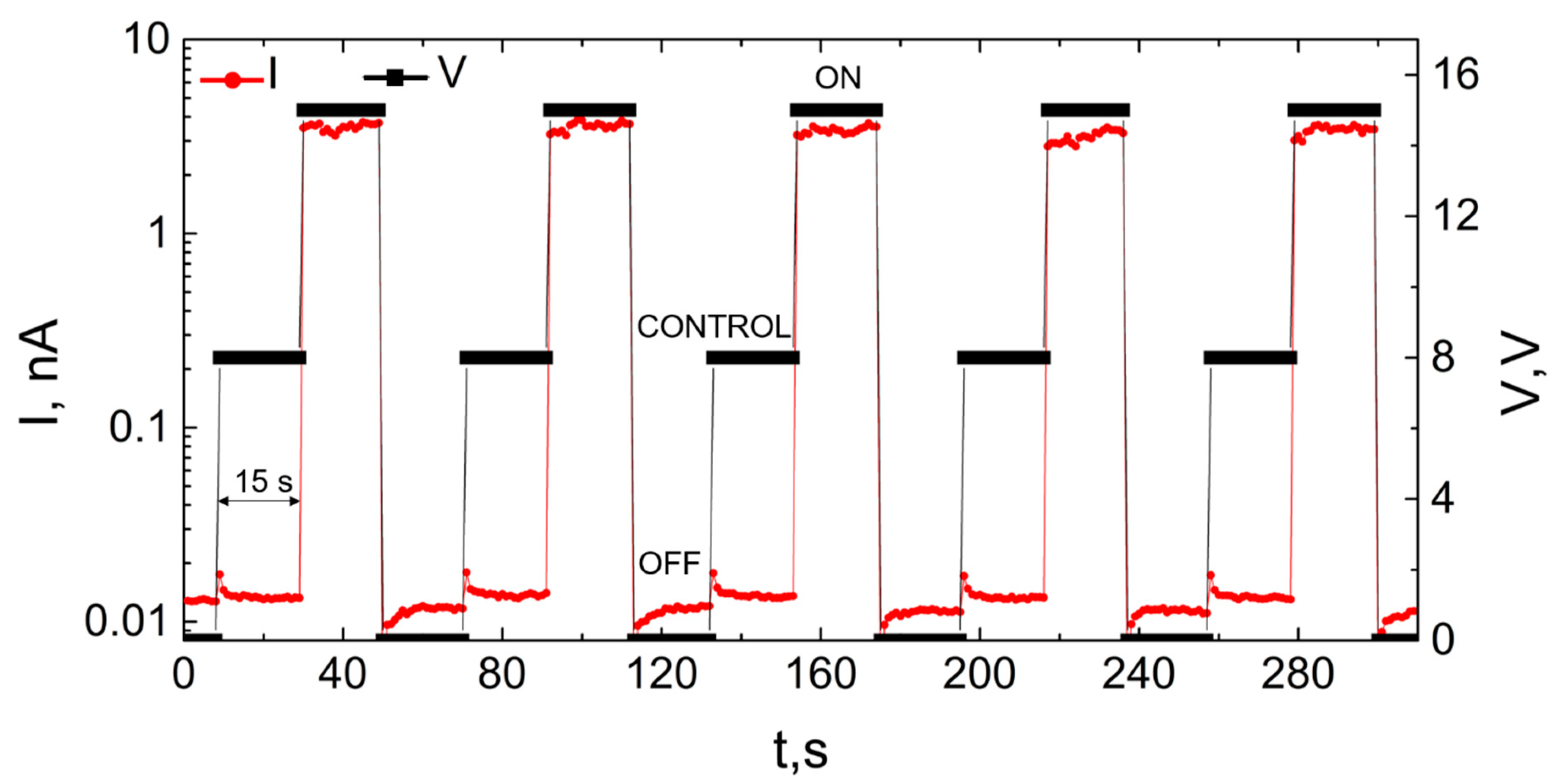
Continued cycling of a double-clamped NEM switch was performed in order to demonstrate the stability of the NEM switch operational parameters. Voltage was applied in square pulses, alternating between 15 V (ON state), 0 V (OFF state), and 8 V (detachment test). The latter voltage value was chosen to be smaller than the switch-ON voltage, but larger than the non-conductive gap region observed in I–V characteristics of the nanowire (Figure 4b) in order to detect the nanowire detachment without visual inspection. The expected values for the current at each state were the following: signal in nA range for 15 V applied voltage and system noise for both 0 V and 8 V. Figure 7 shows a fragment of a typical ON/OFF I(t) cycling, where the switch remains for 15 s in each of the states.

4. Conclusions

In summary, we demonstrate the first fabrication and volatile operation of a NEM switch on-chip that employs bottom-up synthesized semiconductor nanowires as the active elements. It is shown that bottom-up synthesized CuO nanowires can serve as a robust and reliable material for the active element fabrication. By combining conventional lithography, dielectrophoresis, and nanomanipulations, as shown in this work, the fabrication yield can be increased, and device operation assessed more quickly.
We propose a theoretical model for estimating switch-ON voltage, adhesion, elastic force, and nanowires sliding dependence on nanowire’s suspended length, diameter, and distance to the electrode in order to obtain parameters for successful volatile device operation. The model was validated by fabricating NEM switches with the predetermined geometry and testing their operation in gateless double-clamped setup. The calculated VON values were close to those obtained experimentally, and volatile operation was achieved. DEP alignment was successfully employed to also fabricate single-clamped NEM switches.
Both single- and double-clamped CuO nanowire-based switches exhibit abrupt switch-ON, requiring approximately 0.5 V to transit from OFF to ON state. Single-clamped devices show increased switching speeds from the ON to OFF state, which suggests that they can offer faster operation and better energy efficiency than double-clamped configuration switches. However, the demonstrated bottom-up fabrication approach using DEP is currently more suitable for scalable fabrication of double-clamped switches, due to the efficient control of suspended lengths of the nanowires by DEP parameters and electrode geometry. The scalable fabrication of single-clamped switches will require improved control over the suspended length of the nanowire. We also suggest that voltage cycling can be used as a step in NEM switch fabrication to stabilize VON. Further research will be devoted to improving the nanowire-electrode contact in order to improve NEM switch operational characteristics.

Author Contributions

The manuscript was written through contributions of all authors. L.J., J.K., R.M. and D.E. planned the experiments. R.S. synthesized CuO nanowires. A.I.L. and R.M. developed the theoretical model for determining NEM switch operational parameters. M.M.R. carried out dielectrophoretic alignment of CuO nanowires. L.J., R.M., J.K., R.S., M.M.R. performed experiments. D.J. and J.P. supported experimentation and data analysis. L.J. and R.M. wrote the manuscript. D.E., J.P., A.I.L. and D.E. reviewed the manuscript. All authors have read and agreed to the published version of the manuscript.

Funding

This research was funded by the European Regional Development Fund (project no. 1.1.1.1/16/A/256, “Creation of nanoelectromechanical switches”).

Data Availability Statement

The data presented in this study are available on request from the corresponding author.

Acknowledgments

We would like to thank Tom Yager for careful reading and reviewing of the manuscript.

Conflicts of Interest

The authors declare no conflict of interest. The funders had no role in the design of the study; in the collection, analyses, or interpretation of data; in the writing of the manuscript, or in the decision to publish the results.

References

  1. Jasulaneca, L.; Kosmaca, J.; Meija, R.; Andzane, J.; Erts, D. Review: Electrostatically actuated nanobeam-based nanoelectromechanical switches—Materials solutions and operational conditions. Beilstein J. Nanotechnol. 2018, 9, 271–300. [Google Scholar] [CrossRef]
  2. Loh, O.Y.; Espinosa, H.D. Nanoelectromechanical contact switches. Nat. Nanotechnol. 2012, 7, 283–295. [Google Scholar] [CrossRef] [PubMed]
  3. Peschot, A.; Qian, C.; Liu, T.-J.K. Nanoelectromechanical Switches for Low-Power Digital Computing. Micromachines 2015, 6, 1046–1065. [Google Scholar] [CrossRef]
  4. Lee, T.-H.; Bhunia, S.; Mehregany, M. Electromechanical computing at 500 °C with silicon carbide. Science 2010, 329, 1316–1318. [Google Scholar] [CrossRef] [PubMed]
  5. Zhu, Y.; Qin, Q.; Xu, F.; Fan, F.; Ding, Y.; Zhang, T.; Wiley, B.J.; Wang, Z.L. Size effects on elasticity, yielding, and fracture of silver nanowires: In situ experiments. Phys. Rev. B 2012, 85, 045443. [Google Scholar] [CrossRef] [Green Version]
  6. Erts, D.; Lõhmus, A.; Lõhmus, R.; Olin, H. Instrumentation of STM and AFM combined with Transmission Electron Microscope. Appl. Phys. A Mater. Sci. Process. 2001, 72, S71–S74. [Google Scholar] [CrossRef]
  7. Ziegler, K.J.; Lyons, D.M.; Holmes, J.D.; Erts, D.; Polyakov, B.; Olin, H.; Svensson, K.; Olsson, E. Bistable nanoelectromechanical devices. Appl. Phys. Lett. 2004, 84, 4074–4076. [Google Scholar] [CrossRef] [Green Version]
  8. Andzane, J.; Petkov, N.; Livshits, A.I.; Boland, J.J.; Holmes, J.D.; Erts, D. Two-terminal nanoelectromechanical devices based on germanium nanowires. Nano Lett. 2009, 9, 1824–1829. [Google Scholar] [CrossRef]
  9. Andzane, J.; Prikulis, J.; Dvorsek, D.; Mihailovic, D.; Erts, D. Two-terminal nanoelectromechanical bistable switches based on molybdenum-sulfur-iodine molecular wire bundles. Nanotechnology 2010, 21, 125706. [Google Scholar] [CrossRef]
  10. Andzane, J.; Meija, R.; Livshits, A.I.; Prikulis, J.; Biswas, S.; Holmes, J.D.; Erts, D. An AC-assisted single-nanowire electromechanical switch. J. Mater. Chem. C 2013, 1, 7134. [Google Scholar] [CrossRef]
  11. Ke, C.; Espinosa, H.D. In situ electron microscopy electromechanical characterization of a bistable NEMS device. Small 2006, 2, 1484–1489. [Google Scholar] [CrossRef] [PubMed]
  12. Meija, R.; Livshits, A.I.; Kosmaca, J.; Jasulaneca, L.; Andzane, J.; Biswas, S.; Holmes, J.D.; Erts, D. Resonance assisted jump-in voltage reduction for electrostatically actuated nanobeam-based gateless NEM switches. Nanotechnology 2019, 30, 385203. [Google Scholar] [CrossRef]
  13. Lee, S.W.; Lee, D.S.; Morjan, R.E.; Jhang, S.H.; Sveningsson, M.; Nerushev, O.A.; Park, Y.W.; Campbell, E.E.B. A three-terminal carbon nanorelay. Nano Lett. 2004, 4, 2027–2030. [Google Scholar] [CrossRef]
  14. Czaplewski, D.A.; Patrizi, G.A.; Kraus, G.M.; Wendt, J.R.; Nordquist, C.D.; Wolfley, S.L.; Baker, M.S.; De Boer, M.P. A nanomechanical switch for integration with CMOS logic. J. Micromech. Microeng. 2009, 19, 85003. [Google Scholar] [CrossRef]
  15. Muñoz-Gamarra, J.L.; Uranga, A.; Barniol, N. Nanomechanical switches based on metal-insulator-metal capacitors from a standard complementary-metal-oxide semiconductor technology. Appl. Phys. Lett. 2014, 104, 243105. [Google Scholar] [CrossRef] [Green Version]
  16. Muñoz-Gamarra, J.L.; Uranga, A.; Barniol, N. CMOS-NEMS Copper Switches Monolithically Integrated Using a 65 nm CMOS Technology. Micromachines 2016, 7, 30. [Google Scholar] [CrossRef] [PubMed] [Green Version]
  17. Arkan, E.F.; Sacchetto, D.; Yildiz, I.; Leblebici, Y.; Alaca, B.E. Monolithic integration of Si nanowires with metallic electrodes: NEMS resonator and switch applications. J. Micromech. Microeng. 2011, 21, 125018. [Google Scholar] [CrossRef]
  18. Feng, X.L.; Matheny, M.H.; Zorman, C.A.; Mehregany, M.; Roukes, M.L. Low voltage nanoelectromechanical switches based on silicon carbide nanowires. Nano Lett. 2010, 10, 2891–2896. [Google Scholar] [CrossRef]
  19. Jasulaneca, L.; Meija, R.; Livshits, A.I.; Prikulis, J.; Biswas, S.; Holmes, J.D.; Erts, D. Determination of Young’s modulus of Sb2S3 nanowires by in situ resonance and bending methods. Beilstein J. Nanotechnol. 2016, 7, 278–283. [Google Scholar] [CrossRef] [Green Version]
  20. Kosmaca, J.; Meija, R.; Antsov, M.; Kunakova, G.; Sondors, R.; Iatsunskyi, I.; Coy, E.; Doherty, J.; Biswas, S.; Holmes, J.D.; et al. Investigating the mechanical properties of GeSn nanowires. Nanoscale 2019, 11, 13612–13619. [Google Scholar] [CrossRef]
  21. Kosmaca, J.; Jasulaneca, L.; Meija, R.; Andzane, J.; Romanova, M.; Kunakova, G.; Erts, D. Young’s modulus and indirect morphological analysis of Bi2Se3 nanoribbons by resonance measurements. Nanotechnology 2017, 28, 325701. [Google Scholar] [CrossRef]
  22. Meija, R.; Kosmaca, J.; Jasulaneca, L.; Petersons, K.; Biswas, S.; Holmes, J.D.; Erts, D. Electric current induced modification of germanium nanowire NEM switch contact. Nanotechnology 2015, 26, 195503. [Google Scholar] [CrossRef] [PubMed]
  23. Lee, J.O.; Song, Y.H.; Kim, M.W.; Kang, M.H.; Oh, J.S.; Yang, H.H.; Yoon, J.B. A sub-1-volt nanoelectromechanical switching device. Nat. Nanotechnol. 2013, 8, 36–40. [Google Scholar] [CrossRef] [PubMed]
  24. Qian, Y.; Soon, B.W.; Singh, P.; Campanella, H.; Lee, C. All metal nanoelectromechanical switch working at 300 °C for rugged electronics applications. Nanoscale 2014, 6, 5606–5611. [Google Scholar] [CrossRef] [PubMed]
  25. Yu, M.-F.; Lourie, O.; Dyer, M.J.; Moloni, K.; Kelly, T.F.; Ruoff, R.S. Strength and breaking mechanism of multiwalled carbon nanotubes under tensile load. Science 2000, 287, 637–640. [Google Scholar] [CrossRef] [PubMed] [Green Version]
  26. Kaul, A.B.; Wong, E.W.; Epp, L.; Hunt, B.D. Electromechanical carbon nanotube switches for high-frequency applications. Nano Lett. 2006, 6, 942–947. [Google Scholar] [CrossRef]
  27. Loh, O.; Wei, X.; Sullivan, J.; Ocola, L.E.; Divan, R.; Espinosa, H.D. Carbon-Carbon Contacts for Robust Nanoelectromechanical Switches. Adv. Mater. 2012, 24, 2463–2468. [Google Scholar] [CrossRef]
  28. Ngo, L.T.; Almécija, D.; Sader, J.E.; Daly, B.; Petkov, N.; Holmes, J.D.; Erts, D.; Boland, J.J. Ultimate-strength germanium nanowires. Nano Lett. 2006, 6, 2964–2968. [Google Scholar] [CrossRef]
  29. Andzane, J.; Prikulis, J.; Meija, R.; Kosmaca, J.; Biswas, S.; Holmes, J.D.; Erts, D. Application of Ge Nanowire for Two-Input Bistable Nanoelectromechanical Switch. Mater. Sci. Medzg. 2013, 19, 254–257. [Google Scholar] [CrossRef] [Green Version]
  30. Sondors, R.; Kosmaca, J.; Kunakova, G.; Jasulaneca, L.; Ramma, M.M.; Meija, R.; Kauranens, E.; Antsov, M.; Erts, D. Size distribution, mechanical and electrical properties of CuO nanowires grown by modified thermal oxidation methods. Nanomaterials 2020, 10, 1051. [Google Scholar] [CrossRef]
  31. Tan, E.P.S.; Zhu, Y.; Yu, T.; Dai, L.; Sow, C.H.; Tan, V.B.C.; Lim, C.T. Crystallinity and surface effects on Young’s modulus of CuO nanowires. Appl. Phys. Lett. 2007, 90, 163112. [Google Scholar] [CrossRef]
  32. Cha, S.N.; Jang, J.E.; Choi, Y.; Amaratunga, G.A.J.; Kang, D.-J.; Hasko, D.G.; Jung, J.E.; Kim, J.M. Fabrication of a nanoelectromechanical switch using a suspended carbon nanotube. Appl. Phys. Lett. 2005, 86, 83105. [Google Scholar] [CrossRef]
  33. Ramma, M.M.; Katkevics, J.; Jasulaneca, L.; Kunakova, G.; Sondors, R.; Meija, R.; Erts, D.; Kosmaca, J. Dielectrophoretically aligned CuO nanowire interconnects for NEMS sensors. Surf. Interfaces 2020. submitted. [Google Scholar]
  34. Collet, M.; Salomon, S.; Klein, N.Y.; Seichepine, F.; Vieu, C.; Nicu, L.; Larrieu, G. Large-scale assembly of single nanowires through capillary-assisted dielectrophoresis. Adv. Mater. 2015, 27, 1268–1273. [Google Scholar] [CrossRef] [PubMed]
  35. Freer, E.M.; Grachev, O.; Duan, X.; Martin, S.; Stumbo, D.P. High-yield self-limiting single-nanowire assembly with dielectrophoresis. Nat. Nanotechnol. 2010, 5, 525–530. [Google Scholar] [CrossRef]
  36. Subramanian, A.; Alt, A.R.; Dong, L.; Kratochvil, B.E.; Bolognesi, C.R.; Nelson, B.J. Electrostatic actuation and electromechanical switching behavior of one-dimensional nanostructures. ACS Nano 2009, 3, 2953–2964. [Google Scholar] [CrossRef]
  37. Kosmaca, J.; Andzane, J.; Prikulis, J.; Biswas, S.; Holmes, J.D.; Erts, D. Application of a Nanoelectromechanical Mass Sensor for the Manipulation and Characterisation of Graphene and Graphite Flakes. Sci. Adv. Mater. 2014, 3, 552–557. [Google Scholar] [CrossRef]
  38. Li, Q.; Koo, S.-M.; Edelstein, M.D.; Suehle, J.S.; Richter, C. A Silicon nanowire electromechanical switches for logic device application. Nanotechnology 2007, 18, 315202. [Google Scholar] [CrossRef]
  39. Jiang, X.; Herricks, T.; Xia, Y. CuO Nanowires Can Be Synthesized by Heating Copper Substrates in Air. Nano Lett. 2002, 2, 1333–1338. [Google Scholar] [CrossRef]
  40. Dong, L.; Chirayos, V.; Bush, J.; Jiao, J.; Dubin, V.M.; Chebian, R.V.; Ono, Y.; Conley, J.F.; Ulrich, B.D. Floating-potential dielectrophoresis-controlled fabrication of single-carbon-nanotube transistors and their electrical properties. J. Phys. Chem. B 2005, 109, 13148–13153. [Google Scholar] [CrossRef]
  41. Palapati, N.K.R.; Pomerantseva, E.; Subramanian, A. Single nanowire manipulation within dielectrophoretic force fields in the sub-crossover frequency regime. Nanoscale 2015, 7, 3109–3116. [Google Scholar] [CrossRef] [PubMed] [Green Version]
  42. Livshits, A.I.; Jasulaneca, L.; Kosmaca, J.; Meija, R.; Holmes, J.D.; Erts, D. Extra tension at electrode-nanowire adhesive contacts in nano-electromechanical devices. Eur. J. Mech. A/Solids 2017, 66, 412–422. [Google Scholar] [CrossRef]
  43. Carpick, R.W.; Ogletree, D.F.; Salmeron, M. A general equation for fitting contact area and friction vs load measurements. J. Colloid Interface Sci. 1999, 211, 395–400. [Google Scholar] [CrossRef]
  44. Kunakova, G.; Meija, R.; Bite, I.; Prikulis, J.; Kosmaca, J.; Varghese, J.; Holmes, J.D.; Erts, D. Sensing properties of assembled Bi2S3 nanowire arrays. Phys. Scr. 2015, 90, 094017. [Google Scholar] [CrossRef]
  45. Wu, J.; Yin, B.; Wu, F.; Myung, Y.; Banerjee, P. Charge transport in single CuO nanowires. Appl. Phys. Lett. 2014, 105, 183506. [Google Scholar] [CrossRef]
  46. Hummelgård, M.; Zhang, R.; Carlberg, T.; Vengust, D.; Dvorsek, D.; Mihailovic, D.; Olin, H. Nanowire transformation and annealing by Joule heating. Nanotechnology 2010, 21, 165704. [Google Scholar] [CrossRef] [PubMed]
  47. Ryan, P.; Wu, Y.C.; Somu, S.; Adams, G.; McGruer, N. Single-walled carbon nanotube electromechanical switching behavior with shoulder slip. J. Micromech. Microeng. 2011, 21, 045028. [Google Scholar] [CrossRef]
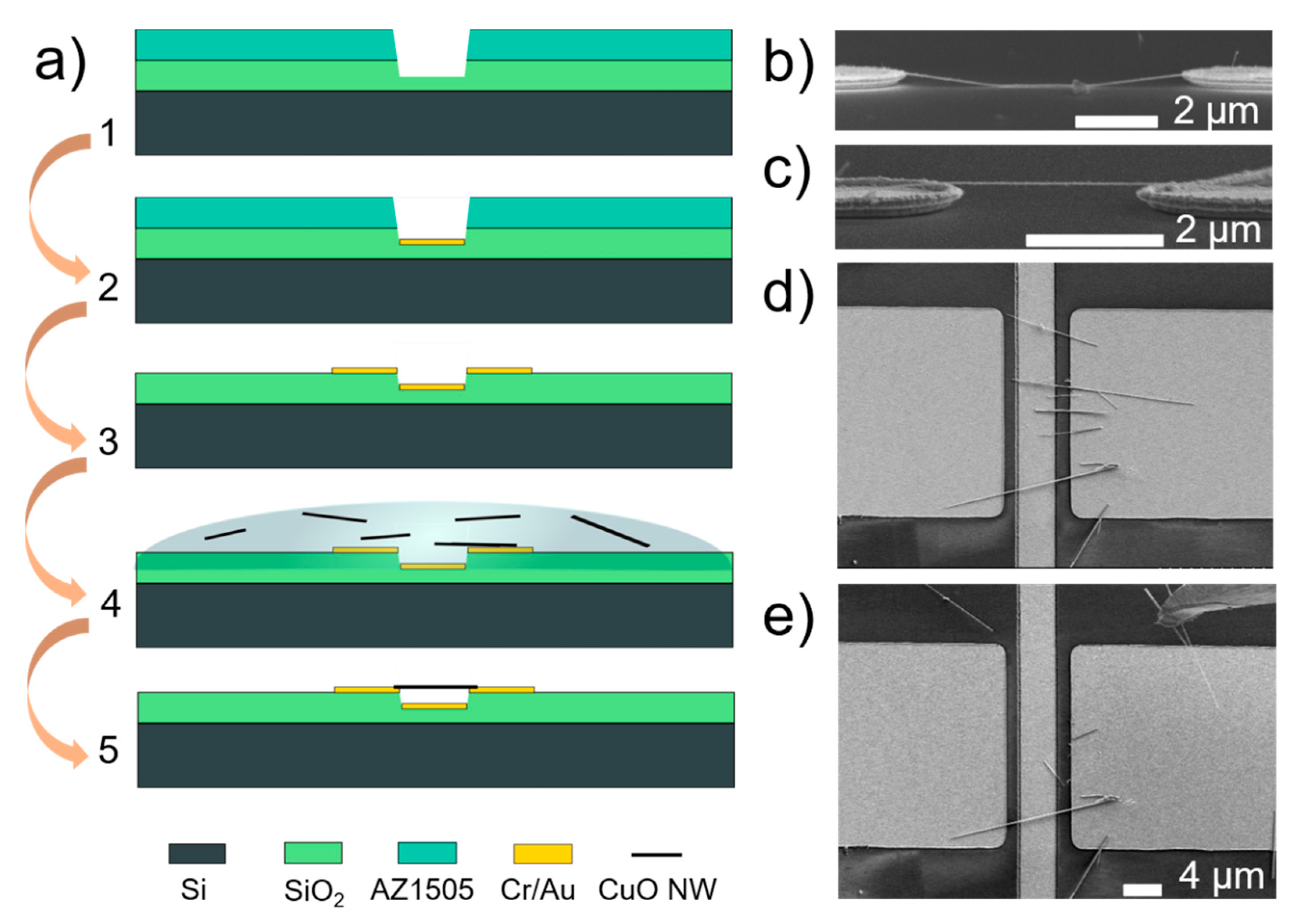
Figure 1. (a) Process flow for fabrication of microelectrodes involving etching of thermal SiO2 (1), deposition of metal electrodes (2, 3) and dielectrophoretic assembly and supercritical drying (4) to yield the final suspended device (5). SEM images showing side view of a single nanowire aligned on 2 µm wide electrodes by (b) DEP without supercritical drying, (c) dielectrophoresis (DEP) followed by supercritical drying; (d) SEM image showing top-view of multiple nanowires aligned on 20 µm wide electrodes; and, (e) the removal of excess nanowires by nanomanipulations with etched gold tip (tip shown in upper right side of the image).
Nanomaterials 11 00117 g001
Figure 2. (a) Optical microscope image of a device connected to a micropatterned gold electrode line that joins it with other devices; (b) SEM image of a double-clamped single nanoelectromechanical (NEM) switch device in an array of 2 μm wide electrodes; (c) Schematics for a double-clamped nanowire switch in OFF and (d) ON state; (e) SEM image of a single-clamped nanowire in an electrically identical setup with wide (20 μm) DEP electrodes; (f) Schematics for a single-clamped nanowire switch in OFF and (g) ON state. Relevant design parameters shown in (c,d,f,g) are suspended nanowire length L0, nanowire diameter d and distance between nanowire and electrode z0.
Nanomaterials 11 00117 g002
Figure 3. (a) Schematics of the relevant forces and parameters for the VON estimation for a double-clamped nanowire with suspended length L0, diameter d (radius R) and initial distance to the electrode z0. (b) Calculations of VON as a function of nanowire diameter for different distances between the nanowire and the electrode z and suspended lengths L0 for a Young’s modulus of 155 GPa, assuming a rigid clamping at the nanowire ends. The lines are drawn as guide to the eye. The suspended lengths are marked by line type (dashed line 6 µm, solid line 8 µm, dotted line 8.6 µm), distances are marked by colored shapes (red square corresponds to 120 nm, blue triangle to 180 nm, and green circle to 200 nm).
Nanomaterials 11 00117 g003
Figure 4. (a) Comparison of experimentally determined and calculated VON values for six samples (labeled 1…6) with different nanowire diameter d and suspended length L0 values and two initial distances between the nanowire and the electrode z0 (120 nm and 190 nm). VON was calculated for two different cases: with and without sliding of the nanowire ends. (b) I–V cycling characteristics of a single device (#6) with voltage applied between S contacts. I–V cycling starts—from maximum voltage absolute value |Vmax| of 10 V. The absolute value of maximum voltage is increased during every next cycle. Inset zooms in on the I–V plots for voltages up to 8 V, showing a reduction of contact resistance.
Nanomaterials 11 00117 g004
Figure 5. (a) Switch I–V cycling from 0 V to 30 V and back to 0 V shows stepwise decrease of VON for every next cycle (cycles from 1 to 5) until (b) reaching a stable NEM switch operation regime with constant VON at 12.5 V and VOFF at 4.5–8 V (cycles 1 to 7: I–V cycling from 0 V to 15 V and back to 0 V). Upwards arrows mark transition to ON state, downwards arrows–transition to OFF state. For this device nanowire’s diameter d = 150 nm, L0 = 6.7 µm, and z0 = 190 nm.
Nanomaterials 11 00117 g005
Figure 6. CuO nanowire-based NEM switch in a single-clamped configuration. SEM image of the NEM switch in (a) OFF state, (b) ON state; (c) Switch I–V cycling showing sharp transition to ON (at 30 V) and OFF (at 13–17 V) states, four switching cycles are shown. Upwards arrows mark transition to ON state, downwards arrows–transition to OFF state. Dimensions for this device: suspended length L0 = 3 μm, diameter d = 80 nm, and the initial distance between nanowire and electrode z0 = 190 nm.
Nanomaterials 11 00117 g006
Figure 7. Variation of NEM switch current levels (red circles) at different applied voltages (black squares) of 0 V (OFF), 8 V (OFF, control), 15 V (ON) during repeatable switching. For 0 V and 8 V, the current stays at the noise level, whereas ON current reaches nA level, when applied voltage is 15 V.
Nanomaterials 11 00117 g007
Publisher’s Note: MDPI stays neutral with regard to jurisdictional claims in published maps and institutional affiliations.