Article

Titanium Dioxide-Coated Zinc Oxide Nanorods as an Efficient Photoelectrode in Dye-Sensitized Solar Cells

1
School of Systems Engineering, Kochi University of Technology, Kami, Kochi 782-8502, Japan
2
Center for Nanotechnology, Kochi University of Technology, Kami, Kochi 782-8502, Japan
*
Author to whom correspondence should be addressed.
Nanomaterials 2020, 10(8), 1598; https://doi.org/10.3390/nano10081598
Submission received: 14 July 2020 / Revised: 6 August 2020 / Accepted: 12 August 2020 / Published: 14 August 2020
(This article belongs to the Special Issue Nanostructured Materials for Solar Cell Applications)

Abstract

:
Well-arrayed zinc oxide nanorods applied as photoelectrodes for dye-sensitized solar cells were synthesized on an aluminum-doped zinc oxide substrate by the multi-annealing method. In order to improve the chemical stability and surface-to-volume ratio of photoanodes in dye-sensitized solar cells, the synthesized zinc oxide nanorods were coated with pure anatase phase titanium dioxide film using a novel mist chemical vapor deposition method. The effects of the titanium dioxide film on the morphological, structural, optical, and photovoltaic properties of zinc oxide–titanium dioxide core–shell nanorods were investigated. It was found that the diameter and surface-to-volume ratio of zinc oxide nanorods were significantly increased by coating them with titanium dioxide thin film. The power conversion efficiency of dye-sensitized solar cells was improved from 1.31% to 2.68% by coating titanium dioxide film onto the surface of zinc oxide nanorods.

1. Introduction

Since Grätzel et al. developed the titanium dioxide (TiO2)-based dye-sensitized solar cell (DSSC) in 1991 [1], the DSSC has emerged as a promising photovoltaic device, due to its promising power conversion efficiency (PCE), low fabrication cost, and low toxicity [2,3,4,5]. Hitherto, it has been reported that TiO2-based DSSCs achieved a notable PCE of over 14% [6]. However, further improvements in PCE are difficult to achieve due to some disadvantages in current TiO2-based DSSCs, such as the low carrier transportation rate of TiO2 resulting from its low electron mobility, as well as the difficulty in fabricating TiO2 nanostructures with a large surface-to-volume ratio [7,8]. Recently, zinc oxide (ZnO) has been widely investigated in different types of solar cells [9,10,11]. As an alternative photoanode material of DSSCs, ZnO has attracted much attention because it exhibits a similar bandgap and electron injection process from excited dye molecules to TiO2 [12,13]. Moreover, the electron mobility of ZnO (200~1000 cm2/(V∙s)) is much higher than that of TiO2 (0.1~4 cm2/(V∙s)) [14], which will enhance electron transportation. Additionally, compared with TiO2, it is much easier to fabricate ZnO as various nanostructures to enlarge the surface-to-volume ratio [15]. Therefore, ZnO-based nanostructures and nanocomposites have much potential for application as a photoanode material to improve the PCE of DSSC.
However, the poor chemical stability of ZnO in the acidic dye solution and electrolyte solution of DSSCs has hampered its wider applicability as a photoanode material in DSSCs [16]. Additionally, defects easily form in ZnO, which increases the Zn2+/dye complex and the electron–hole recombination at the interface [17,18,19,20]. In order to overcome the shortcomings of ZnO-based photoanodes, one solution is to coat a chemically stable shell onto the surface of as-deposited ZnO. This core–shell structure can passivate ZnO’s surface to reduce the complex and form an energy barrier, thereby reducing the electron–hole recombination [21]. Among different ZnO-based nanocomposites, one of the most promising structures is ZnO–TiO2’s core–shell nanostructure. According to the literature [22,23,24,25], the PCE of ZnO photoanode-based DSSCs can be improved by about one to five times by replacing the ZnO photoanode with a corresponding ZnO–TiO2 core–shell nanostructure. It is reported that ZnO’s nanostructure could be coated with TiO2 thin film using the sol–gel method [26], solution method [27], and atomic layer deposition [28]. However, the difficulties that arise with the uniformity and also in controlling the thickness of the TiO2 layer are still unsolved.
Based on our previous study, DSSCs with a high PCE could be achieved by controlling the vertical alignment of ZnO nanorods and the quality of transparent conductive substrates [29,30,31]. In addition, mist chemical vapor deposition (mist CVD) has been proven to be an effective method for modifying ZnO nanorods [32,33]. In this study, ZnO nanorods with vertical alignment were fabricated by a multi-annealing process in reducing ambient. Compared with ZnO nanorods fabricated by other methods, the ZnO nanorods fabricated by multi-annealing showed a higher concentration of oxygen vacancies. The oxygen vacancies were generated due to the effect of reducing ambient and they enhanced the conductivity of ZnO nanorods. However, the oxygen vacancies on the surface of ZnO nanorods will trigger the recombination of electrons. In order to solve this issue, the TiO2 thin layer was coated on ZnO nanorods by the mist CVD method to prevent the recombination of electrons and enhance the chemical stability of electrodes. Compared with other methods, the combination of the multiple annealing process and mist CVD method is an effective method to fabricate ZnO–TiO2 core–shell nanorods applied as photoelectrodes for DSSCs. Figure 1 shows the fabrication mechanism and working principle of ZnO–TiO2 core–shell nanorods. The electrons are injected from excited dye molecules to the conduction band (CB) of TiO2. Then, the electrons are transferred from the CB of TiO2 to the CB of ZnO. The ZnO core has high electron mobility and the TiO2 shell can protect the ZnO core from corrosion and suppress the recombination of electrons. After coating, the obtained ZnO–TiO2 core–shell nanorods, as well as the as-deposited ZnO nanorods, were used to fabricate DSSCs for comparison. The effects of TiO2 coating on the properties of ZnO–TiO2 core–shell nanorods were investigated in detail.

2. Materials and Methods

2.1. Deposition of Thin Films

The aluminum-doped ZnO (AZO, 300 nm) thin films were deposited on alkali-free glass sheets (Eagle XG, Corning Inc., Corning, NY, USA) using a conventional radio frequency (RF, 13.56 MHz) magnetron sputtering system with an AZO target (2 wt.% Al2O3). Following the deposition of AZO films, ZnO films with a 500 nm thickness were deposited on AZO by the same sputtering system with a ZnO target (5N). Table 1 shows the deposition conditions of the AZO film and ZnO film. Argon was selected as the working gas, the flow rate of which was maintained at 30 sccm. During the deposition, the working distance and temperature were set and maintained at 60 mm and 150 °C, respectively. The pressure and RF power for AZO film deposition were maintained at 1 Pa and 60 W. For the deposition of ZnO, the pressure and RF power were held at 7 Pa and 180 W.

2.2. Fabrication of ZnO Nanorods

After sputtering deposition, the fabricated ZnO films were treated using a multi-annealing process in a conventional annealing furnace. As shown in Table 2, the temperature was firstly kept at 300 °C for 2 h in a forming gas ambient (H2:N2 = 1.96%) to increase the density of zinc seeds on the surface. Then, the temperature was increased to 450 °C and kept at this level for 3 h for forming gas to produce the ZnO nanorods. Before the third forming gas annealing process, oxygen was introduced into the furnace for 40 min for surface oxidation to avoid an excessive reducing reaction. For safety considerations, nitrogen was introduced for 5 min between the forming gas and oxygen annealing processes.

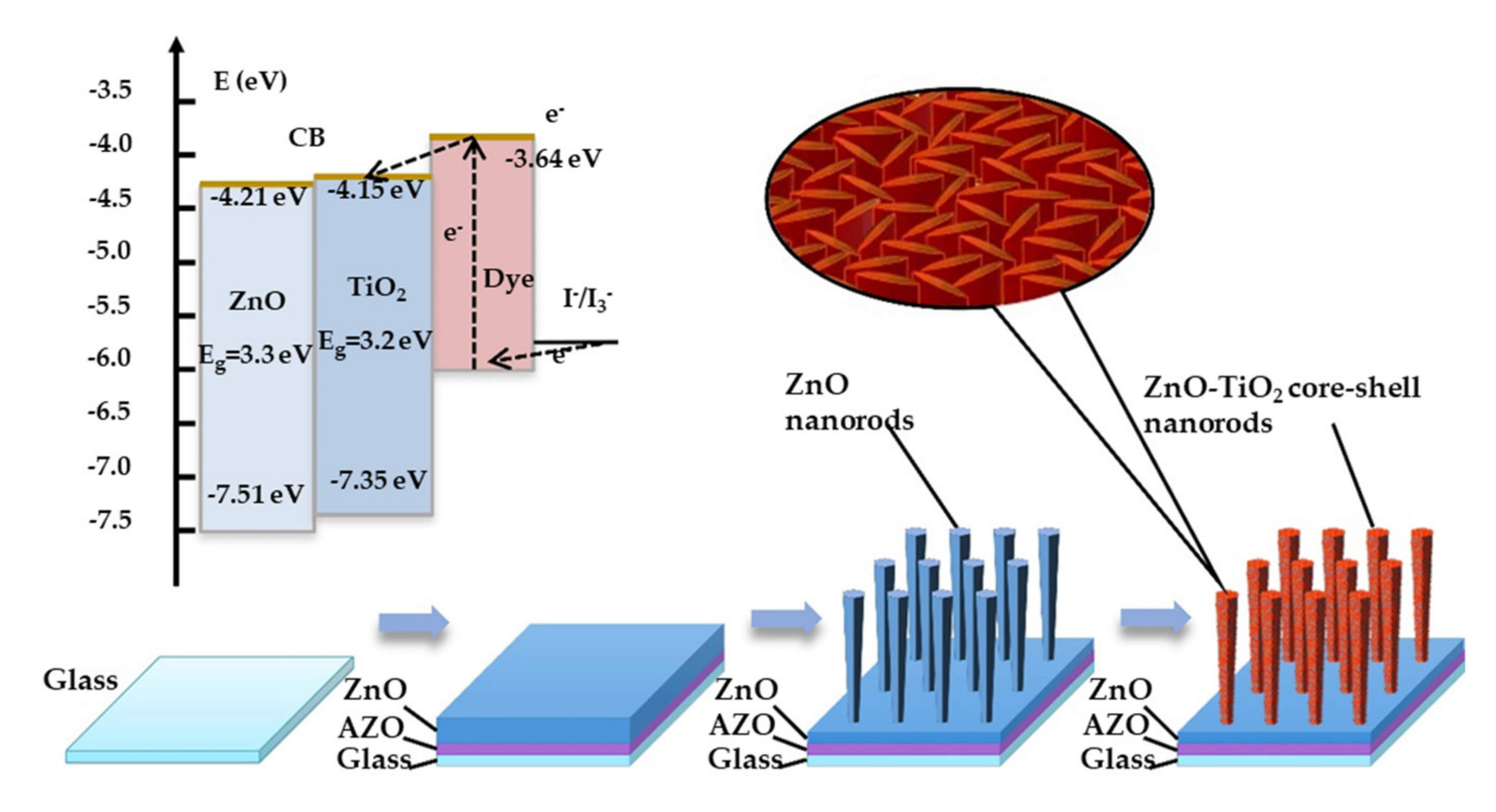
2.3. Fabrication of ZnO–TiO2 Core–Shell Nanorods

Finally, TiO2 film was coated onto the surface of the fabricated ZnO nanorods by a mist CVD system. Table 3 shows the deposition condition of the TiO2 film. An ethanolic titanium tetraisopropoxide (TTIP, purity > 95.0%, Wako Pure Chemical Industries, Ltd., Osaka, Japan) solution with a concentration of 0.10 mol/L was prepared as the precursor solution. Mist droplets were generated from the precursor solution by ultrasonic atomization (2.4 MHz) and transferred to the reaction chamber by compressed air. The sample of as-deposited ZnO nanorods was placed in the reaction chamber and heated to 450 °C during the coating process.

2.4. Fabrication of DSSC

The obtained ZnO–TiO2 core–shell nanorods, as well as the as-deposited ZnO nanorods, were applied as photoanodes to fabricate DSSCs for comparison. N719 (Sigma Aldrich, St. Louis, MO, USA) was used as a dye sensitizer. The photoanodes were immersed in an ethanoic dye solution with a concentration of 5 × 10⁻⁴ mol/L for 12 h. A solution containing 0.10 mol/L lithium iodine and 0.05 mol/L iodine was used as the electrolyte. A platinum-coated indium-doped tin oxide film on glass was applied as the counter-electrode. Six samples of DSSCs were fabricated and investigated to confirm their reproducibility.

2.5. Characterization

The morphological properties of the AZO film, as-deposited ZnO nanorods, and ZnO–TiO2 core–shell nanorods were evaluated using field emission scanning electron microscopy (FE-SEM, JSM-7400F, JEOL, Tokyo, Japan) and transmission emission microscopy (TEM, JEM 2100F, JEOL, Tokyo, Japan). The structural properties of the AZO film were measured by X-ray diffraction (XRD, ATX-G, Rigaku, Tokyo, Japan). The structural properties of the as-deposited ZnO nanorods and ZnO–TiO2 core–shell nanorods were investigated by grazing incidence X-ray diffraction (GIXRD, ATX-G, Rigaku, Tokyo, Japan). The optical properties of the as-deposited ZnO nanorods and ZnO–TiO2 core–shell nanorods were obtained using a spectrophotometer (U-4100, Hitachi, Tokyo, Japan). The fabricated DSSCs were characterized using a solar simulator (PEC-L01, AM 1.5 G, 100 mW/cm2, Peccell Technologies Inc., Yokohama, Japan) and a source meter (Keithley 2400, Keithley Instruments Inc., Solon, OH, USA). All of the measurements were carried out at room temperature.

3. Results

The XRD pattern of the AZO film is shown in Figure 2. It was found that only the (002) diffraction peak was observed in the XRD pattern, which indicated that the AZO films had highly (002) preferred orientation with a c-axis perpendicular to the substrates. The insert image in Figure 2 shows the FE-SEM top view image of the AZO film. It is confirmed that an AZO film with a uniform surface was obtained after deposition.
The FE-SEM images of the as-deposited ZnO nanorods and ZnO–TiO2 core–shell nanorods are shown in Figure 3. The details of single nanorods are shown in the inset images. The as-deposited ZnO nanorods showed a well-arrayed hexagonal structure with a smooth surface. Compared with the as-deposited ZnO nanorods, the ZnO–TiO2 core–shell nanorods had a higher surface roughness and a larger diameter. Intertwined TiO2 nanosheets were observed on the surface of the ZnO–TiO2 core–shell nanorods, indicating that the TiO2 film was successfully coated onto the surface of the ZnO nanorods. Figure 3c shows the TEM image of a single ZnO–TiO2 core–shell nanorod. It was confirmed that the thickness of the TiO2 shell on the ZnO nanorods was around 15 nm.
The GIXRD patterns of the as-deposited ZnO nanorods and ZnO–TiO2 core–shell nanorods are shown in Figure 4. It was found that only the (002) diffraction peak was observed in the GIXRD pattern of the as-deposited ZnO nanorods, suggesting that both the ZnO film and ZnO nanorods had highly (002) preferred orientation with a c-axis perpendicular to the substrates. This agrees well with the FE-SEM results. In the GIXRD pattern of the ZnO–TiO2 core–shell nanorods, the observed peaks corresponded with the (101), (200), (211), (204), (220), and (215) diffraction peaks of the anatase phase TiO2 and the (002) diffraction peak of ZnO. All of the diffraction peaks of TiO2 were identified and corresponded with the anatase phase of TiO2 (JCPDS 21-1272), indicating that the TiO2 film coated on ZnO nanorods was pure anatase phase.
The optical transmission spectra of the as-deposited ZnO nanorods and ZnO–TiO2 core–shell nanorods are shown in Figure 5. The as-deposited ZnO nanorods showed a high transmittance of 75% in visible range. After coating with TiO2 film, the transmittance of the nanorods in visible range decreased to 55%, due to the scattering of TiO2 nanosheets. It is well-known that the bandgap of material can be calculated from the transmittance data by the following equations [34,35]:
α = 1 d ln 1 T
α h ν 2 = A h ν E g
where α is the absorption coefficient, d the thickness of material, T the transmittance, the incident photon energy, A a constant, and Eg the bandgap. A plot of (αhν)2 as a function of made to determine Eg by linear fitting is shown in Figure 6. After fitting, the bandgap of the as-deposited ZnO nanorods was determined as around 3.32 eV, corresponding with the bandgap of bulk ZnO (3.37 eV). The bandgap of the ZnO–TiO2 core–shell nanorods was around 3.28 eV, corresponding with the bandgap of anatase phase TiO2 (3.2 eV).
Figure 7 shows the J-V characteristics of the demonstrated DSSCs applying as-deposited ZnO nanorods and ZnO–TiO2 core–shell nanorods as photoanodes. Compared with the DSSCs using as-deposited ZnO nanorods, the DSSCs applying ZnO–TiO2 core–shell nanorods showed higher open circuit voltage (VOC), higher short circuit current density (JSC), higher fill factor (FF), and higher PCE. After coating with TiO2, the VOC of the DSSCs increased from 0.60 V to 0.63 V, and the JSC increased from 5.01 mA/cm2 to 6.73 mA/cm2. It was found that the FF increased from 43.41% to 63.13%, and the PCE increased from 1.31% to 2.68%. The results showed good reproducibility by checking all of the DSSCs samples. The significant improvement of the FF and PCE was due to the great improvement in the JSC, which could be explained as follows: Firstly, the TiO2 shell increased the surface-to-volume ratio of the ZnO nanorods. Therefore, more dye molecules were absorbed onto the surface of the nanorods, which enhanced their light harvesting. Secondly, the TiO2 shell has a much lower electron–hole recombination rate than ZnO nanorods, which could greatly improve the efficiency of electron collection. Thirdly, the last step of a multi-annealing process was carried out in a reducing ambient. Consequently, many oxygen vacancies were generated on the surface of the ZnO nanorods. The oxygen vacancies acted as recombination centers, which triggered large amounts of recombination of electrons. After coating with TiO2 film, the recombination of electrons was suppressed. The efficient light harvesting and efficient electron collection contributed to the great improvement in the JSC.

4. Conclusions

Well-arrayed ZnO–TiO2 core–shell nanorods were successfully synthesized on AZO substrates by RF magnetron sputtering, multi-annealing, and the mist CVD method. The morphology of the ZnO nanorods was significantly changed by coating with a TiO2 film. After forming the ZnO–TiO2 core–shell structures, the diameter and surface-to-volume ratio of the nanorods were greatly increased. The PCE of DSSCs applying ZnO nanorods as photoanodes was increased two-fold from 1.31% to 2.68% by coating with TiO2.

Author Contributions

Conceptualization, S.H. and C.L.; methodology, S.H. and C.L.; validation, S.H. and C.L.; investigation, S.H.; data curation, Q.Z. and S.H.; writing—original draft preparation, Q.Z.; writing—review and editing, Q.Z. and C.L.; visualization, Q.Z.; supervision, C.L.; project administration, C.L.; funding acquisition, C.L. All authors have read and agreed to the published version of the manuscript.

Funding

This research was funded by the Ministry of Education, Culture, Sports, Science, and Technology (MEXT) in Japan, grant number [17K06394].

Acknowledgments

The authors gratefully acknowledge the financial support by Grant-in-Aid for Scientific Research from the Ministry of Education, Culture, Sports, Science and Technology (MEXT), Japan. The authors greatly appreciate the assistance of Associate Professor Noriko Nitta in supporting the TEM measurement.

Conflicts of Interest

The authors declare no conflict of interest.

References

  1. O’Regan, B.; Grätzel, M. A low-cost, high-efficiency solar cell based on dye-sensitized. Nature 1991, 353, 737–740. [Google Scholar] [CrossRef]
  2. Prabavathy, N.; Shalini, S.; Balasundaraprabhu, R.; Velauthapillai, D.; Prasanna, S.; Muthukumarasamy, N. Enhancement in the photostability of natural dyes for dye-sensitized solar cell (DSSC) applications: A review. Int. J. Energy Res. 2017, 41, 1372–1396. [Google Scholar] [CrossRef]
  3. Ahmad, M.S.; Pandey, A.K.; Rahim, N.A. Advancements in the development of TiO2 photoanodes and its fabrication methods for dye sensitized solar cell (DSSC) applications. A review. Renew. Sustain. Energy Rev. 2017, 77, 89–108. [Google Scholar] [CrossRef]
  4. Das, T.K.; Ilaiyaraja, P.; Sudakar, C. Template assisted nanoporous TiO2 nanoparticles: The effect of oxygen vacancy defects on photovoltaic performance of DSSC and QDSSC. Sol. Energy 2018, 159, 920–929. [Google Scholar] [CrossRef]
  5. Vaghasiya, J.V.; Sonigara, K.K.; Soni, S.S.; Tan, S.C. Dual functional hetero-anthracene based single component organic ionic conductors as redox mediator cum light harvester for solid state photoelectrochemical cells. J. Mater. Chem. A 2018, 6, 4868–4877. [Google Scholar] [CrossRef]
  6. Kakiage, K.; Aoyama, Y.; Yano, T.; Oya, K.; Fujisawa, J.-I.; Hanaya, M. Highly-efficient dye-sensitized solar cells with collaborative sensitization by silyl-anchor and carboxy-anchor dyes. Chem. Commun. 2015, 51, 15894–15897. [Google Scholar] [CrossRef]
  7. Law, M.; Greene, L.E.; Johnson, J.C.; Saykally, R.; Yang, P. Nanowire dye-sensitized solar cells. Nat. Mater. 2005, 4, 455–459. [Google Scholar] [CrossRef]
  8. Zhang, Q.; Dandeneau, C.S.; Zhou, X.; Cao, G. ZnO nanostructures for dye-sensitized solar cells. Adv. Mater. 2009, 21, 4087–4108. [Google Scholar] [CrossRef]
  9. Gopalan, S.-A.; Gopalan, A.-I.; Vinu, A.; Lee, K.-P.; Kang, S.-W. Solar Energy Materials and Solar Cells A new optical-electrical integrated bu ff er layer design based on gold nanoparticles tethered thiol containing sulfonated polyaniline towards enhancement of solar cell performance. Sol. Energy Mater. Sol. Cells 2018, 174, 112–123. [Google Scholar] [CrossRef]
  10. Nandakumar, D.K.; Vaghasiya, J.V.; Yang, L.; Zhang, Y.; Tan, S.C. A solar cell that breathes in moisture for energy generation. Nano Energy 2020, 68, 104263. [Google Scholar] [CrossRef]
  11. Nandakumar, D.K.; Ravi, S.K.; Zhang, Y.; Guo, N.; Zhang, C.; Tan, S.C. A super hygroscopic hydrogel for harnessing ambient humidity for energy conservation and harvesting. Energy Environ. Sci. 2018, 11, 2179–2187. [Google Scholar] [CrossRef]
  12. Kolodziejczak-Radzimska, A.; Jesionowski, T. Zinc oxide-from synthesis to application: A review. Materials (Basel) 2014, 7, 2833–2881. [Google Scholar] [CrossRef] [Green Version]
  13. Lee, J.-C.; Gopalan, A.-I.; Saianand, G.; Lee, K.-P.; Kim, W.-J. Manganese and graphene included titanium dioxide composite nanowires: Fabrication, characterization and enhanced photocatalytic activities. Nanomaterials 2020, 10, 456. [Google Scholar] [CrossRef] [Green Version]
  14. Tiwana, P.; Docampo, P.; Johnston, M.B.; Snaith, H.J.; Herz, L.M. Electron mobility and injection dynamics in mesoporous ZnO, SnO2, and TiO2 films used in dye-sensitized solar cells. ACS Nano. 2011, 5, 5158–5166. [Google Scholar] [CrossRef]
  15. Gonzalez-Valls, I.; Lira-Cantu, M. Vertically-aligned nanostructures of ZnO for excitonic solar cells: A review. Energy Environ. Sci. 2009, 2, 19–34. [Google Scholar] [CrossRef]
  16. Vittal, R.; Ho, K.-C. Zinc oxide based dye-sensitized solar cells: A review. Renew. Sustain. Energy Rev. 2017, 70, 920–935. [Google Scholar] [CrossRef]
  17. Lu, L.; Li, R.; Fan, K.; Peng, T. Effects of annealing conditions on the photoelectrochemical properties of dye-sensitized solar cells made with ZnO nanoparticles. Sol. Energy. 2010, 84, 844–853. [Google Scholar] [CrossRef]
  18. Ambade, S.B.; Mane, R.S.; Ghule, A.V.; Takwale, M.G.; Abhyankar, A.; Cho, B.W.; Han, S.H. Contact angle measurement: A preliminary diagnostic method for evaluating the performance of ZnO platelet-based dye-sensitized solar cells. Scr. Mater. 2009, 61, 12–15. [Google Scholar] [CrossRef]
  19. Yan, F.; Huang, L.; Zheng, J.; Huang, J.; Lin, Z.; Huang, F.; Wei, M. Effect of surface etching on the efficiency of ZnO-based dye-sensitized solar cells. Langmuir. 2010, 26, 7153–7156. [Google Scholar] [CrossRef]
  20. Horiuchi, H.; Katoh, R.; Hara, K.; Yanagida, M.; Murata, S.; Arakawa, H.; Tachiya, M. Electron injection efficiency from excited N3 into nanocrystalline ZnO films: Effect of (N3-Zn2+) aggregate formation. J. Phys. Chem. B. 2003, 107, 2570–2574. [Google Scholar] [CrossRef]
  21. Law, M.; Greene, L.E.; Radenovic, A.; Kuykendall, T.; Liphardt, J.; Yang, P. ZnO-Al2O3 and ZnO-TiO2 core-shell nanowire dye-sensitized solar cells. J. Phys. Chem. B. 2006, 110, 22652–22663. [Google Scholar] [CrossRef] [PubMed]
  22. Chandiran, A.K.; Abdi-Jalebi, M.; Nazeeruddin, M.K.; Grätzel, M. Analysis of electron transfer properties of ZnO and TiO2 photoanodes for dye-sensitized solar cells. ACS Nano. 2014, 8, 2261–2268. [Google Scholar] [CrossRef] [PubMed]
  23. Atienzar, P.; Ishwara, T.; Illy, B.N.; Ryan, M.P.; O’Regan, B.C.; Durrant, J.R.; Nelson, J. Control of photocurrent generation in polymer/ZnO nanorod solar cells by using a solution-processed TiO2 overlayer. J. Phys. Chem. Lett. 2010, 1, 708–713. [Google Scholar] [CrossRef]
  24. Feng, Y.; Ji, X.; Duan, J.; Zhu, J.; Jiang, J.; Ding, H.; Meng, G.; Ding, R.; Liu, J.; Hu, A.; et al. Synthesis of ZnO@TiO2 core-shell long nanowire arrays and their application on dye-sensitized solar cells. J. Solid State Chem. 2012, 190, 303–308. [Google Scholar] [CrossRef]
  25. Prabakar, K.; Son, M.; Kim, W.-Y.; Kim, H. TiO2 thin film encapsulated ZnO nanorod and nanoflower dye sensitized solar cells. Mater. Chem. Phys. 2011, 125, 12–14. [Google Scholar] [CrossRef]
  26. Zhao, R.; Zhu, L.; Cai, F.; Yang, Z.; Gu, X.; Huang, J.; Cao, L. ZnO/TiO2 core-shell nanowire arrays for enhanced dye-sensitized solar cell efficiency. Appl. Phys. A Mater. Sci. Process. 2013, 113, 67–73. [Google Scholar] [CrossRef]
  27. Goh, G.K.L.; Le, H.Q.; Huang, T.J.; Hui, B.T.T. Low temperature grown ZnO@TiO2 core shell nanorod arrays for dye sensitized solar cell application. J. Solid State Chem. 2014, 214, 17–23. [Google Scholar] [CrossRef]
  28. Greene, L.E.; Law, M.; Yuhas, B.D.; Yang, P. ZnO-TiO2 core-shell nanorod/P3HT solar cells. J. Phys. Chem. C. 2007, 111, 18451–18456. [Google Scholar] [CrossRef]
  29. Li, X.; Li, C.; Kawaharamura, T.; Wang, D.; Nitta, N.; Furuta, M.; Furuta, H.; Hatta, A. Influence of substrates on formation of zinc oxide nanostructures by a novel reducing annealing method. Nanosci. Nanotechnol. Lett. 2014, 6, 174–180. [Google Scholar] [CrossRef]
  30. Li, X.; Li, C.; Hou, S.; Hatta, A.; Yu, J.; Jiang, N. Thickness of ITO thin film influences on fabricating ZnO nanorods applying for dye-sensitized solar cell. Compos. Part B Eng. 2015, 74, 147–152. [Google Scholar] [CrossRef]
  31. Hou, S.; Li, C. Aluminum-doped zinc oxide thin film as seeds layer effects on the alignment of zinc oxide nanorods synthesized in the chemical bath deposition. Thin Solid Films 2016, 605, 37–43. [Google Scholar] [CrossRef]
  32. Li, X.; Li, C.; Kawaharamura, T.; Wang, D.; Nitta, N.; Furuta, M.; Furuta, H.; Hatta, A. Fabrication of zinc oxide nanostructures by mist chemical vapor deposition. Trans. Mater. Res. Soc. Jpn. 2014, 164, 161–164. [Google Scholar] [CrossRef] [Green Version]
  33. Zhang, Q.; Li, C. TiO2 coated ZnO nanorods by mist chemical vapor deposition for application as photoanodes for dye-sensitized solar cells. Nanomaterials 2019, 9, 1339. [Google Scholar] [CrossRef] [PubMed] [Green Version]
  34. Gao, X.; Du, Y.; Meng, X. Cupric oxide film with a record hole mobility of 48.44 cm2/Vs via direct-current reactive magnetron sputtering for perovskite solar cell application. Sol. Energy 2019, 191, 205–209. [Google Scholar] [CrossRef]
  35. Fang, X.S.; Bando, Y.; Shen, G.Z.; Ye, C.H.; Gautam, U.K.; Costa, P.M.F.J.; Zhi, C.Y.; Tang, C.C.; Golberg, D. Ultrafine ZnS nanobelts as field emitters. Adv. Mater. 2007, 19, 2593–2596. [Google Scholar] [CrossRef]
Figure 1. Fabrication mechanism and working principle of the zinc oxide–titanium dioxide (ZnO–TiO2) core–shell nanorod.
Nanomaterials 10 01598 g001
Figure 2. XRD pattern of AZO film (insert image shows the FE-SEM top view image of AZO film).
Nanomaterials 10 01598 g002
Figure 3. FE-SEM images of (a) as-deposited ZnO nanorods, (b) ZnO–TiO2 core–shell nanorods, and (c) TEM image of single ZnO–TiO2 core–shell nanorod ((1) Top view, (2) cross-section view).
Nanomaterials 10 01598 g003
Figure 4. GIXRD patterns of as-deposited ZnO nanorods and ZnO–TiO2 core–shell nanorods.
Nanomaterials 10 01598 g004
Figure 5. Optical transmission spectra of as-deposited ZnO nanorods and ZnO–TiO2 core–shell nanorods.
Nanomaterials 10 01598 g005
Figure 6. Variation of (ahν)2 of the as-deposited ZnO nanorods and ZnO–TiO2 core–shell nanorods as a function of the photon energy ().
Nanomaterials 10 01598 g006
Figure 7. J-V characteristics of demonstrated dye-sensitized solar cells (DSSCs) applying as-deposited ZnO nanorods and ZnO–TiO2 core–shell nanorods as photoanodes.
Nanomaterials 10 01598 g007
Table 1. Deposition conditions of AZO and ZnO films.
FilmAZOZnO
TargetAZO (2 wt.%)ZnO (5N)
Working gas, Flow Rate (sccm)Argon, 30Argon, 30
Working distance (mm)6060
Deposition Temperature (°C)150150
Pressure (Pa)17
RF Power (W)60180
Table 2. Annealing condition.
StepGasTemperature (°C)Time (min)
1H2 in N2 (1.96%)300120
2H2 in N2 (1.96%)450180
3O245040
4H2 in N2 (1.96%)450120
Table 3. Deposition condition of TiO2.
SolventEthanol
SoluteTTIP
Concentration (mol/L)0.10
Deposition Temperature (°C)450
Carrier Gas, Flow Rate (L/min)Compressed Air (dried), 2.5
Dilution Gas, Flow Rate (L/min)Compressed Air (dried), 4.5

