Article

Mechanism-Independent Manipulation of Single-Wall Carbon Nanotubes with Atomic Force Microscopy Tip

College of Engineering, Northeast Agricultural University, Harbin 150030, China
*
Authors to whom correspondence should be addressed.
Nanomaterials 2020, 10(8), 1494; https://doi.org/10.3390/nano10081494
Submission received: 22 June 2020 / Revised: 25 July 2020 / Accepted: 28 July 2020 / Published: 30 July 2020

Abstract

:
Atomic force microscopy (AFM) based nanomanipulation can align the orientation and position of individual carbon nanotubes accurately. However, the flexible deformation during the tip manipulation modifies the original shape of these nanotubes, which could affect its electrical properties and reduce the accuracy of AFM nanomanipulation. Thus, we developed a protocol for searching the synergistic parameter combinations to push single-wall carbon nanotubes (SWCNTs) to maintain their original shape after manipulation as far as possible, without requiring the sample physical properties and the tip-manipulation mechanisms. In the protocol, from a vast search space of manipulating parameters, the differential evolution (DE) algorithm was used to identify the optimal combinations of three parameters rapidly with the DE algorithm and the feedback of the length ratio of SWCNTs before and after manipulation. After optimizing the scale factor F and crossover probability Cr, the values F = 0.4 and Cr = 0.6 were used, and the ratio could reach 0.95 within 5–7 iterations. A parameter region with a higher length ratio was also studied to supply arbitrary pushing parameter combinations for individual manipulation demand. The optimal pushing parameter combination reduces the manipulation trajectory and the tip abrasion, thereby significantly improving the efficiency of tip manipulation for nanowire materials. The protocol for searching the best parameter combinations used in this study can also be extended to manipulate other one-dimensional nanomaterials.

Graphical Abstract

1. Introduction

Because of their high intrinsic carrier mobility, conductivity, and mechanical flexibility [1,2,3], carbon nanotubes (CNTs) were considered as the next material to be integrated into biosensors [4], nanoswitches [5], flexible circuits [6], and field-effect transistors (FETs). However, the individual CNT-based devices require the precise control of the placement and shape of the CNT. Although several methods have been developed for the array bulk of CNTs, such as the dielectrophoresis technique [7], the orientation of CNTs could be controlled by dielectrophoresis force during the CNTs depositing the substrate surface in the liquid. Moreover, the chemical vapor deposition technique [8,9] is another method used to grow CNTs, which could directly align CNTs during the CNT growth process. However, for individual CNTs, the atomic force microscopy (AFM) [10] cantilever tip-based manipulation is more suitable for controlling the shape and placement of CNTs than the methods mentioned above, which could not control the selected CNT collection amount of aligned CNTs accurately.
AFM tip-based nanomanipulation has been intensively studied in the past decade, helping us to fabricate nanodevices and nanostructures or conduct studies for improving our fundamental understanding of the material physical and chemical properties [11,12,13,14,15,16,17,18,19]. However, the AFM tip cannot perform operations of imaging and manipulation simultaneously. Moreover, scanning-manipulating-scanning reduces efficiency and effectiveness, which hinders AFM tip manipulation [20,21]. Thus, some researchers have developed feedback systems based on the manipulating forces concerning technical difficulties [22,23,24], such as the augmented reality system [25,26,27], which could monitor real-time changes of the nanoenvironment during the manipulating process by analyzing the interaction forces among the tip, substrate, and manipulating target. Some AFM tip control algorithms and drift-compensation methods were also used to push nanoparticles or nanorods [28,29,30,31,32,33,34].
For flexible one-dimensional nanomaterials similar to single-wall carbon nanotubes (SWCNTs), a parallel pushing vector manipulating method [33,35] was developed to translate and rotate the flexible nanowires. In this method, the tip-manipulating path was optimized by the finite element method. The CNT bending process was described with a continuum beam-bending model with the clamped−clamped boundary constraints. The research group also designed an automated manipulation system with a pushing trajectory designed automatically by algorithmic programs. Moreover, some researchers have studied a geometric model to control the deforming CNT length and bending angle based on continuum mechanics to design a manipulation path and prevent the CNTs from buckling deformation [36]. However, the original shape of CNTs is challenging to maintain after the pushing operation because the large aspect ratio makes the following manipulation path difficult to predetermine to assure the designed CNTs shape after manipulating. Moreover, the deformation of CNTs will affect its electrical properties [37,38,39]. These problems brought challenges for nanowires manipulation.
In this study, a multipoint-pushing method with a parallel path was used to push the SWCNTs. The appropriate pushing parameter combinations must be optimized to control the over shape and position accurately. Therefore, the differential evolution (DE) algorithm [40] was introduced to search for the best operating parameter combinations from the parameter spaces to maintain the SWCNTs removal integral. The DE is a population-based stochastic search method for global optimization to solve large-scale combinatorial optimization problems.
As shown in Figure 1, the operating parameter combination of the proposed strategy includes three pushing parameters, namely, the pushing distance ∆x, the interval between the adjacent pushing path ∆y, and the pushing step n. The parameter ∆x denotes the tip travel distance perpendicular to the axis of CNT, while the interval between the adjacent pushing path ∆y is the gap distance between the adjacent tip travel paths. The parameter n is the number of repetitions of the tip traveling perpendicular to the axis of CNT. The initial value of the parameters is fed into the DE searching system to optimize the best operating parameter combinations with the feedback of the length ratio R of SWCNTs before and after pushing operation. The experimental results indicate that only 5–7 iterations are required to obtain an optimal operating parameter combination, where the length ratio could reach 0.95. With this technique, the CNTs could be transferred with its original shape and the precise position control without optimizing each parameter. Moreover, the pushing path design could prevent the AFM tip from being worn. The method does not require any specific knowledge of the manipulating mechanism and the physical properties of the nanomaterial.

2. Materials and Methods

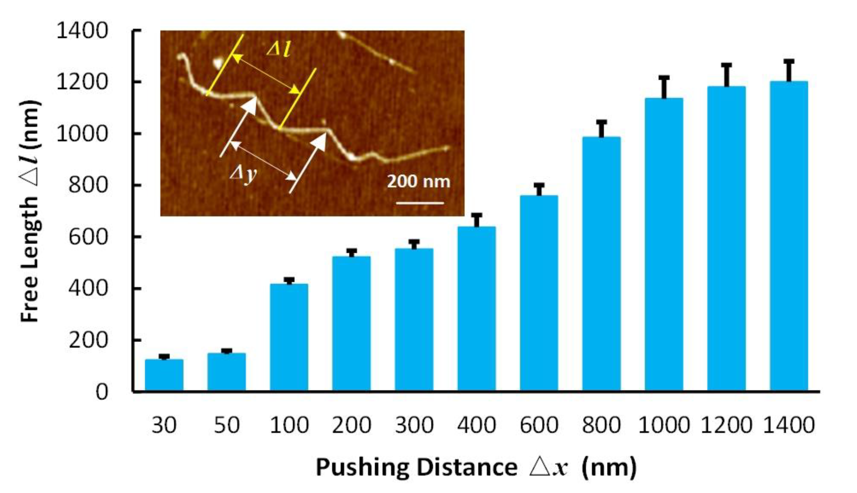
2.1. Manipulating Scheme
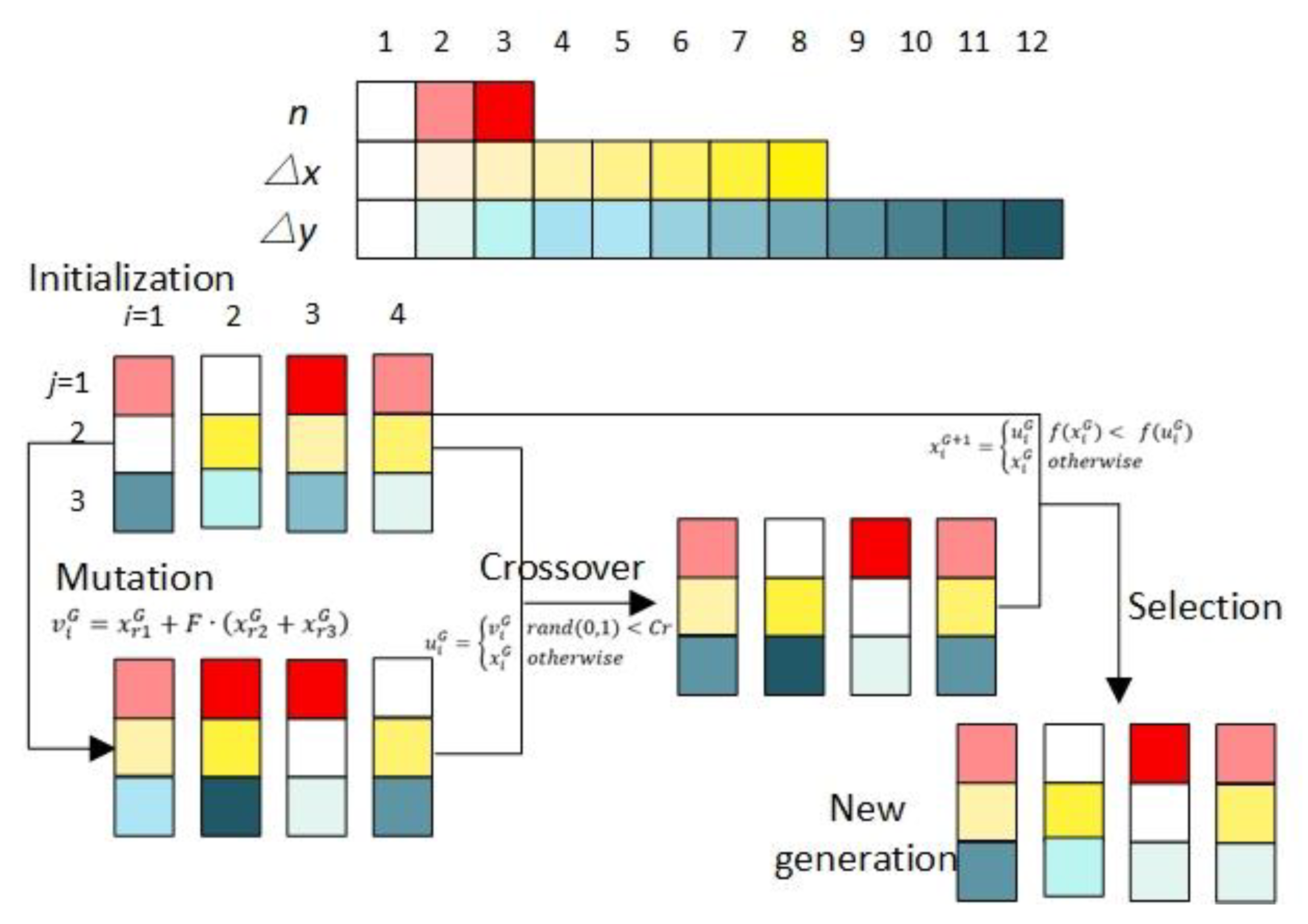
The first iteration of the manipulating scheme started with the implementation of four parallel experiments. Moreover, the parameter combinations for these pushing experiments were generated randomly within a large parameter spaces. After manipulating, the shape of CNTs may have differed from the original shape. Therefore, we used the length ratio of CNTs before and after pushing as the system objective function to evaluate the parameter combinations for the results. For the first iteration, the experimental results could not match our expectation and provide an appropriate parameter combination; thus, the DE search algorithm was used in this study to suggest new combinations for the subsequent iterations. By comparing the length ratio values of the first iteration and new iteration, the new parameter combinations with higher values were generated, corresponding to an improved experimental result. Furthermore, the information was fed back to the search algorithm for the subsequent iteration. Subsequently, the search loop continued until no change through iterations occurred in the objective function, which means that the CNTs’ shape after manipulating reached the best state. This approach expended only a few feedback iterations to obtain the best pushing operation parameter combinations without requiring any specific knowledge of the manipulating mechanism and the physical properties of the nanomaterial.

2.2. DE Algorithm

The stochastic search method, DE algorithm, including initialization, mutation, crossover, and selection, was used for finding the optimal parameter combination to push SWCNTs with precise shape and position control, as shown in Figure 2. In the searching procedures, three parameters, namely, the pushing distance ∆x, the interval between the adjacent pushing path ∆y, and the pushing step n, were used to describe the manipulating condition. Furthermore, the length ratio of CNTs before and after pushing was used as the objective function.

2.2.1. Initialization

Four parallel experiments were implemented simultaneously, and the initialized parameter combinations x i G (G ≥ 0, i = 1, 2, 3, 4) were generated from each parameter space, where G is the G-th iteration, and i corresponds to the label of the parallel experiment. Subsequently, the experiments were performed with the parameter combinations x i G . Moreover, the objective function R (   x i G   ) = L 1 / L is the length ratio of CNTs before and after pushing, where L1 is the length of CNT after pushing, and L is the length before pushing.

2.2.2. Mutation

Once initialized, the DE algorithm starts mutating and recombines the parameter combinations to produce new combinations using: v i G = x r 1 G + F · ( x r 2 G + x r 3 G ) , where x r 1 G ,   x r 2 G ,   and   x r 3 G correspond to the three different parameters selected from the x i G matrix other than x i G   ( G 0 ) . F is the scale factor, which is a real number between 0 and 1, which is used for controlling the mutation probability in the mutation operator. In our research, the effect of F value on the manipulating method was studied, and the best F value was optimized from three values, F = 0.3, F = 0.4, and F = 0.5.

2.2.3. Crossover

A binomial crossover was used in the DE algorithm to increase the parameter diversity by comparing the randomly generated value with the crossover probability Cr. This step created new combinations out of the initial combinations of x i G and the mutation combinations v i G using the following equation.
u i G = { v i G       r a n d ( 0 , 1 ) < C r     x i G       o t h e r w i s e                        
In the equation, the function rand(0, 1) generates a random real number between 0 and 1, and the crossover probability Cr determines the number of components in u i G out from x i G to ensure the heritage from the last iteration. The definite value of Cr ranges from 0 to 1. In this study, the value of Cr was obtained by selecting the best value from five values, 0.3, 0.4, 0.5, 0.6, and 0.7.

2.2.4. Selection

The selection was the final step of the searching algorithm, which determined the parameter combinations for the next iteration by comparing the objective function using x i G   and u i G as in the following equation.
x i G + 1 = { u i G       f ( x i G ) <   f ( u i G )     x i G       o t h e r w i s e                          
Once the new parameter combination x i G + 1 was created, the search loop repeated until the objective function achieved a particular threshold, or the objective function had no significant difference with the last iteration. The final parameter combination was the optimal solution.

2.3. AFM Experiments

The AFM (Dimension Icon, Bruker, Santa Barbara, CA, USA) was used to characterize and manipulate a cantilever probe (TESP, Bruker, Santa Barbara, CA, USA). The spring constant of the rectangular cantilever, the resonant frequency, and the tip radius were approximately 42 N/m, 320 kHz, and 8 nm, respectively. Moreover, the AFM images were obtained on tapping mode, and the pushing operation was implemented under contact mode; both operations were performed in an atmospheric environment.
During scanning, 512 × 512 sample points were used to obtain high-resolution AFM images. The manipulating tip speed was set to 30 nm/s. The manipulating time of a single CNT was up to the manipulating parameters and length of the sample. SWCNT sample was prepared by a standard chemical vapor deposition process. The substrate corresponds to a silicon chip with several hundreds of nanometer thermal oxide on its surface. A 50 μL well-dispersed SWCNT suspension, diluted with an ultrasonic technique, was dropped on the Si substrate surface, and the suspension solvent was evaporated in a dry oven. The length of CNTs used in our experiments, measured with AFM, ranged from 2 to 7 um, and the diameters ranged from 2 to 4 nm. The lateral signal of a position-sensitive detector was acquired with Data Acquisition Card for the tip pushing samples. Moreover, the frictional force between the CNTs and the Si substrate was calculated [24,26,31] to 17 ± 2 nN for the AFM tip pushing distance from 100 nm to 1 um.

3. Results and Discussion

3.1. Parameters Space Optimization

The AFM tip pushing operation would cause the bending behavior of CNT due to the flexibility of nanowires. As shown in Figure 3, the free length Δl, which is the deformation length of CNT with a single pushing path, should be higher than the interval between the adjacent pushing path Δy. Otherwise, part of the CNT would be stayed at the original location rather than transferred to another position, during the manipulating process. In this study, with a pushing distance of more than 1400 nm, the pre-experiment results showed that the length radio R was less than 0.5. After considering these pre-experiment results and the manipulating efficiency, the pushing distance spaces for 30 nm, 50 nm, 100 nm, 200 nm, 300 nm, 400 nm, 600 nm, 700 nm, 800 nm, 1000 nm, 1200 nm, and 1400 nm were found. The free length with different pushing distances was obtained with the AFM tip pushing experiments on the Si substrate, as shown in Figure 3. Note that the free length increment reduced after a pushing distance higher than 1000 nm. Therefore, the maximum value of Δy was set to 1000 nm. The interval between the adjacent pushing path spaces included 50 nm, 100 nm, 200 nm, 300 nm, 400 nm, 600 nm, 800 nm, and 1000 nm. The pushing step spaces number included 1, 2, and 3.

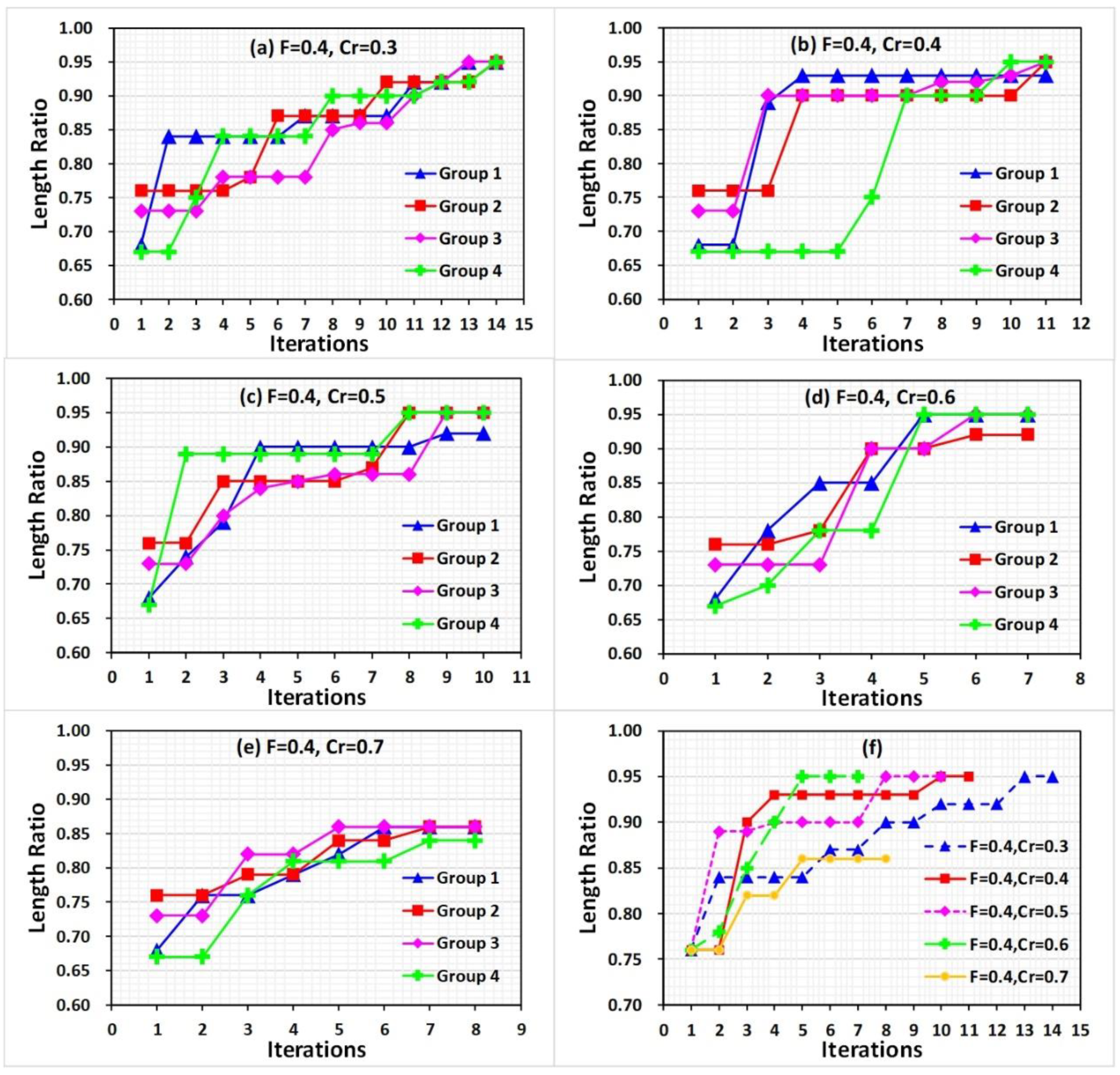
3.2. Intrinsic Parameters of DE Optimization

In the DE search algorithm, except for the manipulating parameters, the intrinsic constant of the scale factor F and the crossover probability Cr also affected the optimization result by affecting the convergence speed and search space. The high scale factor would increase the mutation probability of the parameters, whereas the low value maintains most parameter combinations, similar to the values in the previous iteration. Moreover, the crossover probability determines the searching space; high Cr value improved the local search ability but could lead to premature convergence. For different applications for different intrinsic parameters were considered. In this study, the intrinsic parameters were optimized from the spaces of F = 0.3, 0.4, and 0.5, Cr = 0.3, 0.4, 0.5, 0.6, and 0.7 with the feedback of the length ratio R, which a higher R-value means that the shape of CNTs after manipulation was similar to the original shape before manipulating. Moreover, the straight CNTs were selected in our experiments, and the parameter combination was optimized to avoid the deformation of straight CNTs during manipulation. The manipulating parameter values in parameter combinations were selected from the parameter spaces according to the DE algorithm.

3.2.1. F Value Optimization

The first iteration started from a random generation of manipulating parameters from the parameter spaces. For comparison purposes, Cr = 0.5 and the same starting parameter combinations were used in this section. However, with different F values, the parameter combinations generated in the mutation and crossover for the next iteration may differ. The parameter combinations are listed in Tables S1–S3 in Supplementary Information. Figure 4a–c show the experimental results, where the length ratio values using the starting parameter combinations ranged from 0.66 to 0.76. After several searching iterations, the results indicate that the length ratio curves presented an increasing trend along with the iterations.
The optimization converged to its best value throughout the process. Specifically, with F = 0.3, the curves approach the value 0.87 within seven iterations, which is a local optimization because a low F value reduced the diversity of the pushing parameters in the next iteration, leading to premature convergence. With a higher F value, the variance of the pushing parameters increased the chances to search away from local optima. Thus, with F = 0.4 and 0.5, the peak length ratio values reached 0.95 at seven or eight iterations. Moreover, the three group results reach 0.95 in nine iterations with F = 0.4; however, one group reaches 0.92. With F = 0.5, all group results reached 0.95 in 11 iterations. The curves of the peak value in each iteration step of every set showed improved manipulating results regarding the value of F = 0.4 and 0.5, as shown in Figure 4d. However, with F = 0.4, faster convergence speed and similar results as with F = 0.5 were obtained. Therefore, 0.4 was selected in this study as a scaling factor.

3.2.2. Cr Value Optimization

The same starting parameter combinations of previous experiments were used in this section. Five set considering Cr = 0.3, 0.4, 0.5, 0.6, and 0.7 were designed to evaluate Cr, as shown in Figure 5. For Cr = 0.3, considering all groups, the results reach the value of 0.95 in 14 iterations (see Table S4 in Supplementary Information). With an increase in Cr, the result curves converge faster. Three result curves reached the value 0.95, and the last group reacheed the value 0.92 with Cr = 0.4, 0.5, and 0.6 in 11, 9, and 6 iterations, respectively, as shown in Figure 4b–d (see Tables S2, S5, and S6 in Supplementary Information). However, with the higher Cr value of 0.7, the premature convergence phenomenon could not be avoided, and the result curves approached 0.85 in seven iterations, causing local optimization (see Table S7 in Supplementary Information). Comparing the best result in each iteration step of every set, as shown in Figure 5e, the Cr = 0.6 curve achieved the value 0.95. All group result curves in this set converge at the value 0.95. Therefore, 0.6 was selected in our research as the Cr value.

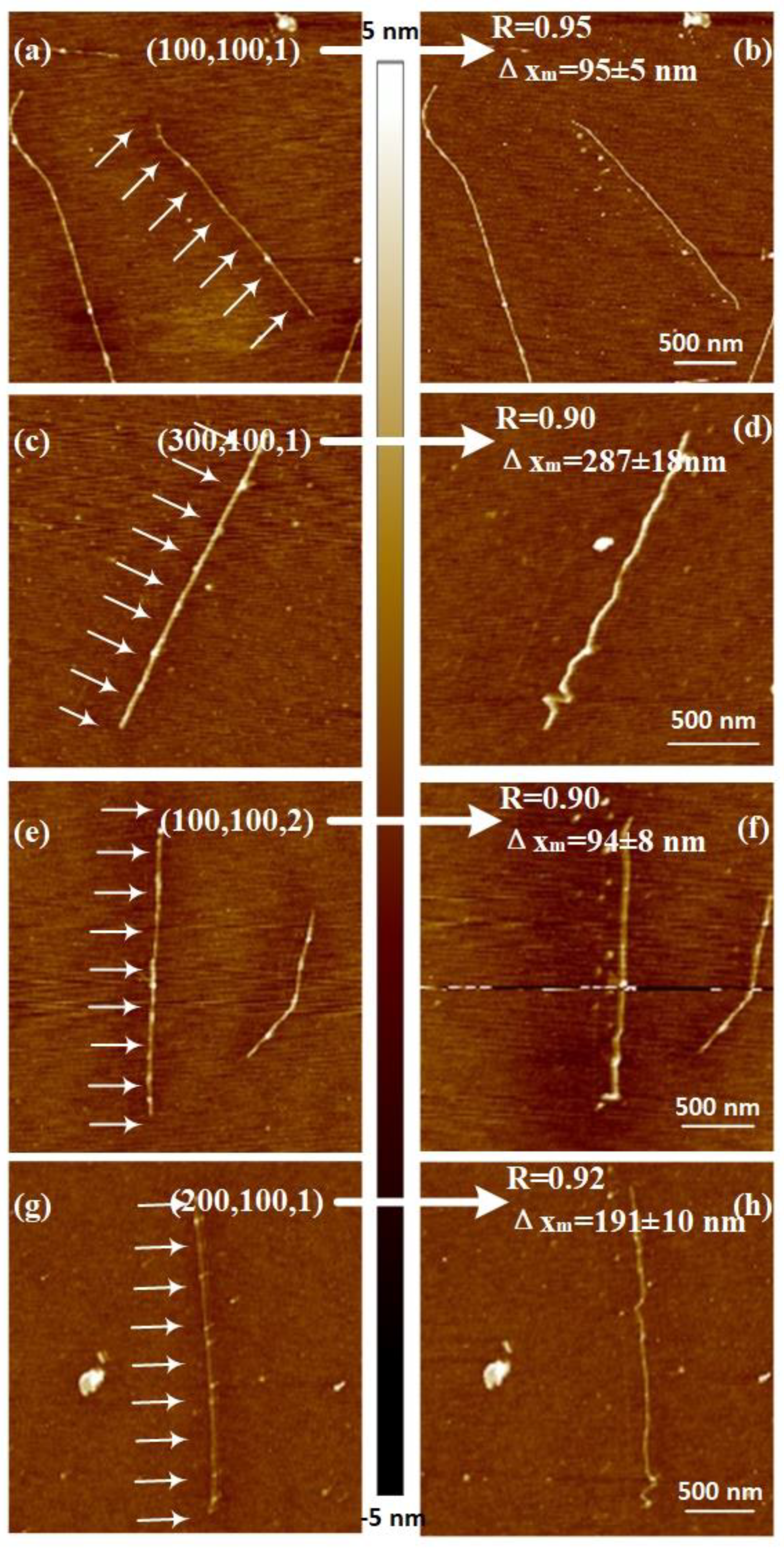
3.3. Pushing Parameter Combination

Considering the less tip wearing and faster-approaching speed to reach the best experimental result, we used F = 0.4 and Cr = 0.6 to study the parameter combination for pushing SWCNT with AFM tip on a silicon substrate, as shown in Figure 5d and Table S6. The result curves had an increasing trend with iterations; however, the parameter of the pushing distance Δx, the interval between the adjacent pushing path Δy, and the pushing step n decrease until reaching the value 0.95 with the parameter combination (100,100,1), i.e., Δx = 100 nm, Δy = 100 nm, and n = 1. Figure 6 shows the AFM images before and after pushing, corresponding to a result above 0.90. The parallel pushing path is denoted in the figure using arrows. Comparing the AFM images before and after manipulating, we found that the CNT with the peak pushing result value of 0.95 was removed, maintaining most of the original straight-line shape. Moreover, other CNTs had some deformation after the pushing operation. The distance between the position of CNTs before and after manipulating Δxm was measured, as shown in Figure 6. The measured values all approached the target pushing distance Δx with a 10% error.
For the armchair CNTs, the effects of bending deformation on their electrical transport properties were calculated [41,42,43]. The transmission function was affected strongly when the bending angles were higher than 45°. Moreover, the electrical resistance increased when the bending angles were higher than 45°. However, for zigzag CNTs, the computed conductance was affected significantly when the bending angles were higher than 20°. In the experiments, the parameter combinations with the experimental result of length ratio above 0.90 could be used for armchair CNTs without affecting the electrical transport properties, as the bending angles were less than 45°. Furthermore, the parameter combinations of the experimental result with a length ratio of 0.95 could be used for zigzag CNTs manipulation, as the bending angles were less than 20°. All the pushing parameter combinations having a length ratio value above 0.90 for all the sets of experiments are listed in Table 1. In the table, almost all combinations having a higher value had only one pushing step. Moreover, for a long pushing distance Δx of 100 or 200 nm, the manipulation value of 0.90 or 0.92 was obtained. For a small Δx of 50 or 100 nm, the length ratio R could reach 0.95. These results were similar for the interval between the adjacent pushing path Δy.
Figure 7 shows the parameter combinations having only one pushing step in Table 1. The first quadrant of Figure 7 was divided into several regions using different lines, which were formed by connecting the combination coordinate points having the same experimental results. A smaller value of the parameters improving experimental results was obtained in previous experiments. Therefore, if the experiment was performed with a parameter combination selected in the region, the length ratio of CNT before and after pushing would be better than the value with combinations on the boundary line. For example, if the pushing parameters were selected in the area surrounded by the blue line, even though the parameters were not in our parameter spaces, the experimental result of the length ratio would be higher than 0.90. This result was demonstrated because the regions with value R > 0.90 were surrounded with the 0.90 line. If a researcher wanted to obtain the best experimental result, the pushing parameters should be selected in the area surrounded by the red line. The parameters region could supply any pushing parameter combination for a user, designing the pushing parameters to achieve an individual demand.

4. Conclusions

The pushing parameters, including the pushing distance, the interval between the adjacent pushing path, and the pushing step, affected the CNT pushing operation substantially. These parameters determine the shape of CNT after the pushing operation. In this study, the DE search algorithm was used to search the optimal pushing parameter combination to avoid the deformation of CNT during manipulation, which could maintain the straight shape of CNT after manipulation similar to before manipulation, as well as the length ratio of CNT before and after pushing operation was set as the objective function. After optimizing the scale factor F and crossover probability Cr, the values 0.4 and 0.6 were used, respectively, to search the optimal pushing parameter combination. With only six iterations and 24 pushing experiments, the best pushing parameter combination (100, 100, 1) was obtained, and the experimental result reached the length ratio value of 0.95.
Moreover, the region of pushing parameters presenting values higher than 0.9 the length ratio value, with a 10% error in the measured pushing distance, was studied to provide arbitrary parameter combinations to researchers, even beyond the analyzed parameter spaces. Furthermore, having a pushing parameters region provides a favorable result for researchers to design the pushing experiments according to their demand. No need for optimizing every parameter saves time and reduces the wearing of AFM tip. Moreover, the fact that the knowledge of the physical properties of samples and the tip manipulation mechanisms are not required is another advantage of this method. Future research will try to characterize the effect of deformation on the physical property of CNTs using the proposed method. We will also try to manipulate other one-dimension nanomaterials, such as the DNA chain. This method could also be extended to other nanomaterial manipulation to assemble nanodevices with precise position and shape control.

Supplementary Materials

The supplementary materials are available online at https://www.mdpi.com/2079-4991/10/8/1494/s1. Table S1: F = 0.3, Cr = 0.5, Table S2: F = 0.4, Cr = 0.5, Table S3: F = 0.5, Cr = 0.5, Table S4: F = 0.4, Cr = 0.3, Table S5: F = 0.4, Cr = 0.4, Table S6: F = 0.4, Cr = 0.6, Table S7: F = 0.4, Cr = 0.7.

Author Contributions

Conceptualization and methodology, L.L. and H.C.; software, D.J.; validation, L.L.; formal analysis, Y.Z.; data curation, R.L. and S.L.; writing—original draft, D.J.; writing—review and editing, D.J. and L.L.; project administration, L.L. and H.C.; funding acquisition, L.L. All authors have read and agreed to the published version of the manuscript.

Funding

This research was supported by the National Natural Science Foundation of China (31701311), and University Nursing Program for Young Scholars with Creative Talents in Heilongjiang Province (UNPYSCT-2017016).

Acknowledgments

The authors would like to thank Northeast Agricultural University colleagues for providing good suggestions regarding the experiments and manuscript. Moreover, we also thank the Editage (www.editage.cn) for English language editing.

Conflicts of Interest

The authors declare no conflict of interest.

References

  1. Park, S.; Vosguerichian, M.; Bao, Z. A Review of Fabrication and Applications of Carbon Nanotube Film-Based Flexible Electronics. Nanoscale 2013, 5, 1727–1752. [Google Scholar] [CrossRef] [PubMed]
  2. Bezryadin, A.; Lau, C. Quantum Suppression of Superconductivity in Ultrathin Nanowires. Nature 2000, 404, 971–974. [Google Scholar] [CrossRef] [PubMed]
  3. Postma, H.W.C.; Teepen, T.; Yao, Z.; Grifoni, M.; Dekker, C. Carbon Nanotube Single-Electron Transistors at Room Temperature. Science 2001, 293, 76–79. [Google Scholar] [CrossRef] [PubMed] [Green Version]
  4. Ishikawa, F.N.; Curreli, M.; Olson, C.A.; Liao, H.-I.; Sun, R.; Roberts, R.W.; Cote, R.J.; Thompson, M.E.; Zhou, C. Importance of Controlling Nanotube Density for Highly Sensitive and Reliable Biosensors Functional in Physiological Conditions. ACS Nano 2010, 4, 6914–6922. [Google Scholar] [CrossRef]
  5. Deshpande, V.V.; Chiu, H.-Y.; Postma, H.W.C.; Miko, C.; Forr, L.; Bockrath, M. Carbon Nanotube Linear Bearing Nanoswitches. Nano Lett. 2006, 6, 1092–1095. [Google Scholar] [CrossRef]
  6. Cao, Q.; Kim, H.; Pimparkar, N.; Kulkarni, J.P.; Wang, C.; Shim, M.; Roy, K.; Alam, M.A.; Rogers, J.A. Medium-Scale Carbon Nanotube Thin-Film Integrated Circuits on Flexible Plastic Substrates. Nature 2008, 454, 495–500. [Google Scholar] [CrossRef]
  7. Tran, C.; Lecao, K.; Bui, T.T.; Dau, V.T. Dielectrophoresis Can Control the Density of CNT Membranes as Confirmed by Experiment and Dissipative Particle Simulation. Carbon 2019, 155, 279–286. [Google Scholar] [CrossRef]
  8. Papadopoulos, C.; Omrane, B. Nanometer-Scale Catalyst Patterning for Controlled Growth of Individual Single-Walled Carbon Nanotubes. Adv. Mater. 2008, 20, 1344–1347. [Google Scholar] [CrossRef]
  9. Rao, S.; Huang, L.; Setyawan, W.; Hong, S. Nanotube Electronics: Large-Scale Assembly of Carbon Nanotubes. Nature 2003, 425, 36–37. [Google Scholar] [CrossRef]
  10. Binnig, G.K.; Quate, C.F.; Gerber, C. The Atomic Force Microscope. Phys. Rev. Lett. 1986, 56, 930–933. [Google Scholar] [CrossRef] [Green Version]
  11. Wang, S.; Shan, Z.; Huang, H. The Mechanical Properties of Nanowires. Adv. Sci. 2017, 4, 1600332. [Google Scholar] [CrossRef] [PubMed]
  12. Kim, H.J.; Kang, K.H.; Kim, D.E. Sliding and Rolling Frictional Behavior of a Single ZnO Nanowire during Manipulation with an AFM. Nanoscale 2013, 5, 6081–6087. [Google Scholar] [CrossRef] [PubMed]
  13. Li, X.; Dong, M.; Jiang, D.; Li, S.; Shang, Y. The Effect of Surface Roughness on Normal Restitution Coefficient, Adhesion Force and Friction Coefficient of the Particle-Wall Collision. Power Technol. 2020, 362, 17–25. [Google Scholar] [CrossRef]
  14. Gui, X.; Xing, Y.; Rong, G.; Cao, Y.; Liu, J. Interaction Forces between Coal and Kaolinite Particles Measured by Atomic Force Microscopy. Powder Technol. 2016, 301, 349–355. [Google Scholar] [CrossRef]
  15. Li, M.; Xi, N.; Wang, Y.; Liu, L. Nanotopographical Surfaces for Regulating Cellular Mechanical Behaviors Investigatedb by Atomic Force Microscopy. ACS Biomate Sci. Eng. 2019, 5, 5036–5050. [Google Scholar] [CrossRef]
  16. Li, M.; Xi, N.; Wang, Y.; Liu, L. Tunable Hybrid Biopolymeric Hydrogel Scaffolds Based on Atomic Force Microscopy Characterizations for Tissue Engineering. IEEE Trans. Nanotechnol. 2019, 18, 315–328. [Google Scholar] [CrossRef]
  17. Wen, Y.; Lu, H.; Shen, Y.; Xie, H. Nanorobotic Manipulation System for 360° Characterization Atomic Force Microscopy. IEEE Trans. Ind. Electron. 2019, 67, 2916–2924. [Google Scholar] [CrossRef]
  18. Miriam, M.; Pablo, A.; Zamora, F.; Cristina, G.; Julio, G. AFM Manipulation of Gold Nanowires to Build Electrical Circuits. Nano Lett. 2019, 19, 5459–5468. [Google Scholar]
  19. Neugirg, B.R.; Koebley, S.R.; Schniepp, H.C.; Fery, A. AFM-Based Mechanical Characterization of Single Nanofibres. Nanoscale 2016, 8, 8414–8426. [Google Scholar] [CrossRef] [Green Version]
  20. Shi, Q.; Yang, Z.; Guo, Y.; Wang, H.; Sun, L.; Huang, Q.; Fukuda, T. A Vision-Based Automated Manipulation System for the Pick-Up of Carbon Nanotubes. IEEE/ASME Trans. Mech. 2017, 22, 845–854. [Google Scholar] [CrossRef]
  21. Lu, H.; Shang, W.; Xie, H.; Shen, Y. Ultrahigh-Precision Rotational Positioning under a Microscope: Nanorobotic System, Modeling, Control. IEEE Trans. Robot. 2018, 34, 497–507. [Google Scholar] [CrossRef]
  22. Bolopion, A.; Régnier, S. A Review of Haptic Feedback Teleoperation Systems for Micromanipulation and Microassembly. IEEE Trans. Autom. Sci. Eng. 2013, 10, 496–502. [Google Scholar] [CrossRef] [Green Version]
  23. Onal, C.D.; Ozcan, O.; Sitti, M. Automated 2-D Nanoparticle Manipulation Force Microscopy. IEEE Trans. Nanotechnol. 2011, 10, 472–481. [Google Scholar] [CrossRef]
  24. Korayem, M.H.; Saraie, M.B.; Saraee, M.B. Analysis the Effect of Different Geometries of AFM’s Cantilever on the Dynamic Behavior and the Critical Forces of Three-Dimensional Manipulation. Ultramicroscopy 2017, 175, 9–24. [Google Scholar] [CrossRef] [PubMed]
  25. Li, G.; Xi, N.; Yu, M.; Fung, W. Development of Augmented Reality System for AFM-Based Nanomanipulation. IEEE/ASME Trans. Mech. 2004, 9, 358–365. [Google Scholar] [CrossRef]
  26. Li, G.; Xi, N.; Chen, H.; Pomeroy, C.; Prokos, M. “Videolized” Atomic Force Microscopy for Interactive Nanomanipulation and Nanoassembly. IEEE Trans. Nanotechnol. 2005, 4, 605–615. [Google Scholar] [CrossRef]
  27. Liu, L.; Luo, Y.; Xi, N.; Wang, Y.; Zhang, J.; Li, G. Sensor Referenced Real-Time Videolization of Atomic Force Microscopy for Nanomanipulations. IEEE/ASME Trans. Mech. 2008, 13, 76–85. [Google Scholar] [CrossRef] [Green Version]
  28. Hou, J.; Liu, L.; Wang, Z.; Wang, Z.; Xi, N.; Wang, Y.; Wu, C.; Dong, Z.; Yuan, S. AFM-Based Robotic Nano-Hand for Stable Manipulation at Nanoscale. IEEE Trans. Autom. Sci. Eng. 2013, 10, 285–295. [Google Scholar] [CrossRef]
  29. Yuan, S.; Wang, Z.; Xi, N.; Wang, Y.; Liu, L. AFM Tip Position Control in situ for Effective Nano-Manipulation. IEEE/ASME Trans. Mech. 2018, 23, 2825–2836. [Google Scholar] [CrossRef]
  30. Korayem, M.H.; Khaksar, H. Investigating the Impact Models for Nanoparticles Manipulation Based on Atomic Force Microscope (According To Contact Mechanics). Powder Technol. 2019, 344, 17–26. [Google Scholar] [CrossRef]
  31. Saraee, M.B.; Korayem, M.H. Dynamic Modeling and Simulation of 3D Manipulation on Rough Surfaces Based on Developed Adhesion Models. Int. J. Adv. Manuf. Technol. 2017, 88, 529–545. [Google Scholar] [CrossRef]
  32. Hou, L.; Wang, S.; Huang, H. A Simple Criterion for Determining the Static Friction Force between Nanowires and Flat Substrates Using the Most-Bent-State Method. Nanotechnology 2015, 26, 165702. [Google Scholar] [CrossRef] [PubMed]
  33. Liu, H.; Wu, S.; Zhang, J.; Bai, H.; Jin, F.; Pang, H.; Hu, X. Strategies for the AFM Based Manipulation of Silver Nanowires on a Flat Surface. Nanotechnology 2017, 28, 365301. [Google Scholar] [CrossRef] [PubMed]
  34. Lee, S.W. Mechanical Properties of Suspended Individual Carbon Nanotube Studied by Atomic Force Microscope. Synth. Met. 2016, 216, 88–92. [Google Scholar] [CrossRef]
  35. Zhang, C.; Wu, S.; Fu, X. Automated Manipulation of Carbon Nanotubes Using Atomic Force Microscopy. J. Nanosci. Nanotechnol. 2013, 13, 598–602. [Google Scholar] [CrossRef]
  36. Yang, S.C.; Qian, X. Controlled Manipulation of Flexible Carbon Nanotubes through Shape-Dependent Pushing by Atomic Force Microscopy. Langmuir 2013, 29, 11793–11801. [Google Scholar] [CrossRef]
  37. Zhang, X.C.; Myers, E.B.; Sader, J.E.; Roukes, M.L. Nanomechanical Torsional Resonators for Frequency-Shift Infrared Thermal Sensing. Nano Lett. 2013, 13, 1528–1534. [Google Scholar] [CrossRef] [Green Version]
  38. Storn, R.; Hall, A.R.; Falvo, M.R.; Superfine, R.; Washburn, S. Electromechanical response of single-walled carbon nanotubes to torsional strain in a self-contained device. Nature Nanotechnol. 2007, 2, 413–416. [Google Scholar]
  39. Mazzoni, M.S.; Chacham, H. Bandgap closure of a flattened semiconductor carbon nanotube: A first-principles study. Appl. Phys. Lett. 2000, 76, 1561–1563. [Google Scholar] [CrossRef]
  40. Storn, R.; Price, K. Differential Evolution—A Simple and Efficient Heuristic for Global Optimization over Continuous Spaces. J. Glob. Optim. 1997, 11, 341–359. [Google Scholar] [CrossRef]
  41. Maiti, A.; Alexei, S.; Anantram, M.P. Electronic transport through carbon nanotubes: Effects of structural deformation and tube chirality. Phys. Rev. Lett. 2002, 88, 126805. [Google Scholar] [CrossRef] [PubMed] [Green Version]
  42. Rochefort, A.; Avouris, P.; Lesage, F.; Salahub, D.R. Electrical and mechanical properties of distorted carbon nanotubes. Phys. Rev. B 1999, 60, 13824–13830. [Google Scholar] [CrossRef] [Green Version]
  43. Charlier, J.; Blase, X.; Roche, S. Electronic and transport properties of nanotubes. Rev. Mod. Phys. 2007, 79, 677–732. [Google Scholar] [CrossRef] [Green Version]
Figure 1. Schematic of the manipulation system. The diagram depicts the tip pushing carbon nanotubes (CNTs) technique loop used for manipulating parameter optimization based on the differential evolution (DE) algorithm and three pushing parameters. Pushing distance Δx, the interval between the adjacent pushing path Δy, and pushing step n were fed into the manipulating system. The length ratio of CNT before and after pushing operation was the objective function used to suggest new parameters in the next iteration. The optimization process continues until reaching the desired state.
Nanomaterials 10 01494 g001
Figure 2. A schematic illustration of DE algorithm.
Nanomaterials 10 01494 g002
Figure 3. Carbon nanotube (CNT) bending test by atomic force microscopy (AFM) pushing operation with a single path. The bar chart describes the free length Δl under pushing distance Δx used in our study. The inlet image is the AFM image illustrated the free length and the interval between adjacent pushing path Δy.
Nanomaterials 10 01494 g003
Figure 4. Differential evolution based on the length ratio in feedback control for pushing CNT operation with (a) F = 0.3, (b) F = 0.4, and (c) F = 0.5. The peak length ratio value in each step iteration of every set is listed in (d). In each iteration, four groups of combinations were studied.
Nanomaterials 10 01494 g004
Figure 5. Differential evolution based on the length ratio in feedback control for pushing CNT operation with (a) Cr = 0.3, (b) Cr = 0.4, (c) Cr = 0.5, (d) Cr = 0.6, and (e) Cr = 0.7. The peak length ratio value in each step iteration of every set experiments is listed in (f). In each iteration, four groups of combinations were studied.
Nanomaterials 10 01494 g005
Figure 6. AFM images of CNT before and after pushing operation with different parameter combinations. The arrows in the left column of the AFM images denote the multipoint method and pushing direction. (a), (c), (e) and (g) are the AFM images before manipulating operation, (b), (d), (f) and (h) are the AFM images after manipulation with parameter combinations respectively. The vectors in the left column are the parameter combinations used in the manipulation, and R is the length ratio, Δxm is the distance between the position of CNTs before and after manipulating.
Nanomaterials 10 01494 g006
Figure 7. Pushing parameter region with higher length ratio value. The lines were obtained by connecting the same R-value combination points.
Nanomaterials 10 01494 g007
Table 1. Parameter combinations used in manipulating operation having R-value above 0.90 for all experimental data. (Δx, Δy, n) denotes the parameter values in the parameter combination.
R0.900.920.930.95
No.
1(100, 200, 2)(50, 200, 1)(200, 50, 1)(30, 50, 1)
2(200, 200, 1)(100, 200, 1)-(30, 100, 1)
3(300, 100, 1)(200, 100, 1)-(50, 50, 1)
4(400, 50, 1)--(50, 100, 1)
5(100,100,2)--(100, 100, 1)
6---(100, 50, 1)

