Article

2D/1D V2O5 Nanoplates Anchored Carbon Nanofibers as Efficient Separator Interlayer for Highly Stable Lithium–Sulfur Battery

1
School of Materials Science and Engineering, Zhengzhou University, Kexue Ave 100, Zhengzhou 450001, China
2
College of Environment and Materials Engineering, Yantai University, Yantai 264005, China
3
School of Materials Science and Engineering, Shanghai University, Shangda Rd 99, Shanghai 200444, China
*
Authors to whom correspondence should be addressed.
Nanomaterials 2020, 10(4), 705; https://doi.org/10.3390/nano10040705
Submission received: 11 March 2020 / Revised: 1 April 2020 / Accepted: 6 April 2020 / Published: 8 April 2020
(This article belongs to the Special Issue Design and Synthesis of Nanomaterials for Energy Storage)

Abstract

:
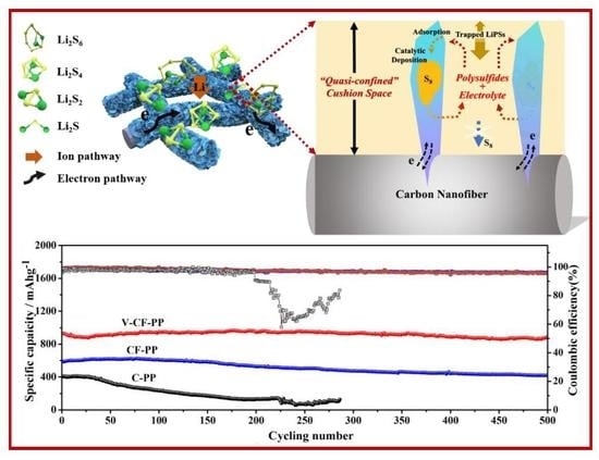
Quick capacity loss due to the polysulfide shuttle effects is a critical challenge for high-performance lithium–sulfur (Li–S) batteries. Herein, a novel 2D/1D V2O5 nanoplates anchored carbon nanofiber (V-CF) interlayer coated on standard polypropylene (PP) separator is constructed, and a stabilization mechanism derived from a quasi-confined cushion space (QCCS) that can flexibly accommodate the polysulfide utilization is demonstrated. The incorporation of the V-CF interlayer ensures stable electron and ion pathway, and significantly enhanced long-term cycling performances are obtained. A Li–S battery assembled with the V-CF membrane exhibited a high initial capacity of 1140.8 mAh·g−1 and a reversed capacitance of 1110.2 mAh·g−1 after 100 cycles at 0.2 C. A high reversible capacity of 887.2 mAh·g−1 is also maintained after 500 cycles at 1 C, reaching an ultra-low decay rate of 0.0093% per cycle. The excellent electrochemical properties, especially the long-term cycling stability, can offer a promising designer protocol for developing highly stable Li–S batteries by introducing well-designed fine architectures to the separator.

Graphical Abstract

1. Introduction

Fast development of portable electronic devices and electric vehicles calls for battery with high energy density and long-lasting cycle performance [1,2]. With the state-of-the-art Li-ion batteries approaching their theoretical limits, lithium–sulfur (Li–S) batteries have been attracting increasing attentions as one of the most promising high-energy-density rechargeable battery systems [3]. Li–S battery can offer a high theoretical capacity of 2567 Wh·kg−1 (the Gibbs energy of the Li/S reaction) [4,5,6], and sulfur is relatively low cost and abundant in nature, which are crucial for the future large-scale applications [7,8,9].
However, practical applications of Li–S batteries remain challenge hindered by several undermining issues such as the highly insulating nature of elemental sulfur (S8) (5 × 10⁻³⁰ S·cm−1 at 25 °C) [10], the large volumetric changes of sulfur during charge and discharge (≈79%) [11,12], as well as the dissolution and shuttling of the lithium polysulfide intermediates (LiPSs, Li2Sx, 4 ≤ x ≤ 8), which result in low utilization and loss of cathode active materials [13]. Massive efforts, including modification of the sulfur cathode, compositional design for the electrolyte, functionalization of the separator, and protection of the active Li anodes, have been devoted to manipulate these deficiencies [14,15,16,17,18,19], e.g., various host materials, including doped carbon and its derivatives [20], metal oxides [21], sulfides [22], and polymers [23], are applied to enhance the chemical or physical affinity with the polysulfides to entrap them within the cathode. Other compounds, like CoS2 [24], MoO3 [25], and CoP [26], can both catalyze the electrochemical conversion of the polysulfides and adsorb them, which are attractive for polysulfide immobilizing in both cathode and separator parts. Quite recently, insertion of membranes (or the so-called interlayers) between the separator and cathode has been demonstrated as a simple and promising approach to alleviate these issues [27,28]. First, the functional layer can serve as a physical barrier to intercept the migration of the soluble LiPSs to the anode side. Additionally, during the discharge–charge process, the interlayer can help reuse the soluble LiPSs, which thus works as a secondary current collector and enhances the utilization of the active materials [29]. Carbon nanotube (CNT)-based conductive porous materials are the most frequently reported interlayers that were applied in Li–S batteries [30]. However, due to the weak interactions between the nonpolar carbon matrix and the polysulfides, the enhancements from these interlayers are still deficient for practical applications [31,32]. Progressively, metal oxides, like TiO2 [33], MnO2 [34], and Fe3O4 [35], etc., have demonstrated the strong adsorption attractions with the LiPSs, by virtue of the intense electrostatic attractions between the metal−oxygen bond and the LiPSs. However, there are still gradual declines of the specific capacity after long-term cycling, especially due to the formation of inactive sulfur species inside the interlayer, which impede the ion pathway and/or increase the interfacial impedance between the electrode and the electrolyte. This influence can become worse when cells are assembled with high S loading content or cycling at a high current density. Further steps on separator interlayers are critically needed to establish stable electron and ion pathway while retaining efficient LiPSs trapping for high-performance Li–S battery.
V2O5 is a well-known layer-structured transition metal oxide that is widely applied in energy storage fields [36,37,38]. Various V2O5 architectures such as nanorod, nanofiber, nanosphere, nanoflower, nanotube, etc., have been developed for applications in Li-ion batteries [39,40,41,42]. Besides, in these years, there were several contributions of V2O5 as the sulfur cathode modification materials [43], where catalytic effect and strong adsorption with the LiPSs were observed [44,45]. Recently, investigations from Guan et al. even demonstrated that V2O5 possess a higher LiPSs adsorption content than the conventionally reported MoS2, FeS, CoS, and Ti4O7 [46]. However, as encountered by other cathode modification materials, specific energy loss (as high as 20–50%) are also accompanied by the incorporation of these inactive host materials. From another perspective, Liu et al. [47] reported that V2O5-coated carbon membrane can work as an effective interlayer that significantly suppresses the LiPSs shuttling and prompts a superior electrochemical performance. It is quite expected that V2O5 can be of much more potentials acting as an interlayer material other than the cathode modification materials in Li–S battery. However, as reported by Liu et al. [47], the semiconductive V2O5 increased the interfacial impedance after direct coating on the carbon surface, resulting in a relatively weak capacitance retention especially when cycling at a high current density. A designer tactic, with considerations of the efficient LiPSs utilization and stable electron and ion pathway building, is required, to fulfill the benefits of V2O5 as an effective interlayer modification material in Li–S battery.
In these regards, we present here a 2D/1D V2O5 nanoplates anchored CF networks as an effective separator interlayer for highly stable Li–S batteries. The CF was prepared by direct carbonization of the electrospun polyacrylonitrile (PAN) membrane, and the near-vertically aligned V2O5 nanoplates on the CF were obtained via a simple hydrothermal process. The specially aligned V2O5 nanoplates on the CF provides a quasi-confined cushion space (QCCS) that flexibly adsorbs and intercepts the soluble LiPSs. Here, an architecture-derived mechanism for building stable ion and electron transportation pathways was proposed. The corresponding Li–S battery assembled with the V-CF decorated PP interlayer exhibited a high initial capacity of 1140.8 mAh·g−1 and a stable reversed capacitance of 1110.2 mAh·g−1 after 100 cycles at 0.2 C, and a high capacity retention of 95.4% after 500 cycles (with a superior low decay rate of 0.0093% per cycle) at 1 C was also demonstrated. These achievements, especially the high retention of the capacity for long-term cycling, are quite high among the emerging high-performance Li–S batteries, which may provide a great potential for construction of highly stable batteries.

2. Experimental

2.1. Raw Chemicals

All chemicals were commercially available and used as received. Polyacrylonitrile (PAN) (Mw = 150,000) and polyvinyl pyrrolidone (PVP) were purchased from Sigma-Aldrich Co., Ltd., Shanghai, China. N, N-Dimethylformamide (DMF) was purchased from Sinopharm Chemical Reagent Co., Ltd., Shanghai, China.

2.2. Preparation of CFs

The carbon fibers were synthesized by electrospinning. Typically, a precursor solution was prepared by dissolving 0.4 g PAN in 5 mL DMF. Then, the above solution was electrospun onto the target rotating collector (aluminum foil, located 10–20 cm from the syringe needle) under a fixed voltage of 16 kV. After that, the as-obtained PAN fibers were peeled off from the collector and placed in a drying oven at 60 °C to remove the residual DMF. Finally, the PAN nanofibers were peroxidized by annealing in air at 280 °C for 1 h, and carbonized at 900 °C for 2 h under flowing N2 atmosphere.

2.3. Preparation of V2O5 Nanoplates Decorated CF

The V2O5 was deposited onto the CF by a hydrothermal method [48,49]. Briefly, 0.2 mL of vanadium (V) oxytriisopropoxide was added into 50 mL isopropanol under stirring. Subsequently, the above-prepared solution (in which Φ-19 mm CFs were immersed) was transferred to a Teflon-lined stainless-steel autoclave, sealed, and kept at 200 °C for 12 h. The as-obtained membrane was taken out, rinsed in ethanol and dried under vacuum at 60 °C overnight, which was finally converted into V-CF by annealing at 280 °C for 1 h in air. The schematic diagram for the synthesis of V-CF is shown in Figure 1.

2.4. Battery Fabrication and Electrochemical Measurements

The cathodes were prepared by mixing the sulfur powder with the grounded carbon fibers as reported in ref [50], which were annealed at 200 °C for 0.5 h under vacuum in a tube furnace. A viscous slurry was prepared by mixing 80 wt.% active materials, 10 wt.% conductive carbon black, and 10 wt.% poly (vinylidene fluoride) (PVDF) in N-methyl-l-2-pyrrolidone (NMP) dispersant. The slurry was casted on an aluminum foil and dried in vacuum at 60 °C for overnight. The electrolyte consisted of 1 mol·L−1 bis(trifluoromethane) sulfonimide lithium salt (LiTFSI) which was dissolved in a mixture of 1,3-dioxolane (DOL) and dimethoxyethane (DME) (1:1 by volume) with 1 wt.% LiNO3. The Li–S batteries were assembled into 2032-type coin cells in an argon-filled glove box (O2 and H2O < 0.1 ppm) with lithium foil as the counter electrode. PP, CF interlayer modified PP (CF-PP), and V-CF interlayer modified PP (V-CF-PP) were applied as the separators for the corresponding cells.

2.5. Saturated Adsorption Content Tests

The content of V2O5 in V-CF was firstly calculated by measuring the weight loss of the oven-dried V-CF samples before and after removing V2O5 in nitric acid solution. For the saturated adsorption content measurement, about 2 mg V-CF sample was added into the sample bottle and stirred with 10 mL electrolyte; then, diluted Li2S6 solution (5 mmol·L−1 in electrolyte) was added slowly, with a 30 min stirring for each one to two drops. The solution evolved quickly from colorless to light yellow after addition of the deep yellow-colored Li2S6 solution, and gradually changed back to colorless because of the V2O5 adsorption. A saturated adsorption state can be obtained when the color of the solution cannot change back after a certain amount of Li2S6 addition, where the saturated adsorption content of the V-CF can be calculated.

2.6. Electrochemical Characterization

The above-fabricated Li–S batteries were cycled between 1.7 and 2.8 V at different current rates on a battery analyzer (Land CT 2001A, Landian, Wuhan, China) at room temperature. The cyclic voltammetry (CV) was tested on an electrochemical workstation (PGSTAT302N, Metrohm, Switzerland) at a scan rate of 0.1 mV·s−1 between 1.7 and 2.8 V. The specific charge and discharge capacities were calculated based on the mass of the elemental sulfur. The electrochemical impedance spectra (EIS) of the working electrodes were recorded on the electrochemical workstation in a two-electrode configuration with frequency ranging from 10−2 to 105 Hz.
Symmetric batteries were also assembled to investigate the catalytic properties, by placing two of the V-CF (or CF) electrodes into a standard 2032-type coin cell with Celgard 2400 membrane as the separator and 80.0 μL Li2S6 as the active material. The CV measurements of the symmetric batteries were operated on an electrochemical workstation at a scan rate of 50 mV·s−1 between −0.8 and 0.8 V.

2.7. Characterization

The morphologies and structure of the CF and V-CF were characterized by scanning electron microscopy (SEM) (Auriga FIB, Zeiss, Germany) and transmission electron microscope (TEM) (Tecnai G220, Hillsboro, OR, USA). The X-ray photoelectron spectroscopy (XPS) spectra was recorded on a PHI Quantera SXM (ULVAC-PHI, Kanagawa, Japan) system with Al/K anode (photon energy = 1486.6 eV) mono X-ray source. Powder X-ray diffraction (XRD) pattern was collected on an X-ray diffractometer (DX-2700BH, Dandong Haoyuan, Liaoning, China) using Cu Kα as the radiation source. Raman spectroscopy was measured by a Confotec MR520 instrument (Graben, Germany) with an excitation wavelength of 532 nm. Thermogravimetric (TG) analysis was performed under nitrogen flow using a thermal analyzer apparatus (STA449F3, NETZSCH, Germany) with heating rate of 10 °C·min−1 from room temperature to 800 °C. Nitrogen adsorption–desorption isotherms were recorded on an ASAP 2460 (Micromeritics Shanghai, China) apparatus at temperature of 77 K. The specific surface area and the pore structure were measured by the nitrogen sorption using a physisorption analyzer (JW-BK112, Beijing, China). The zeta potential was conducted by a Zeta potentiometer (JS94H, Shanghai, China).

3. Results and Discussion

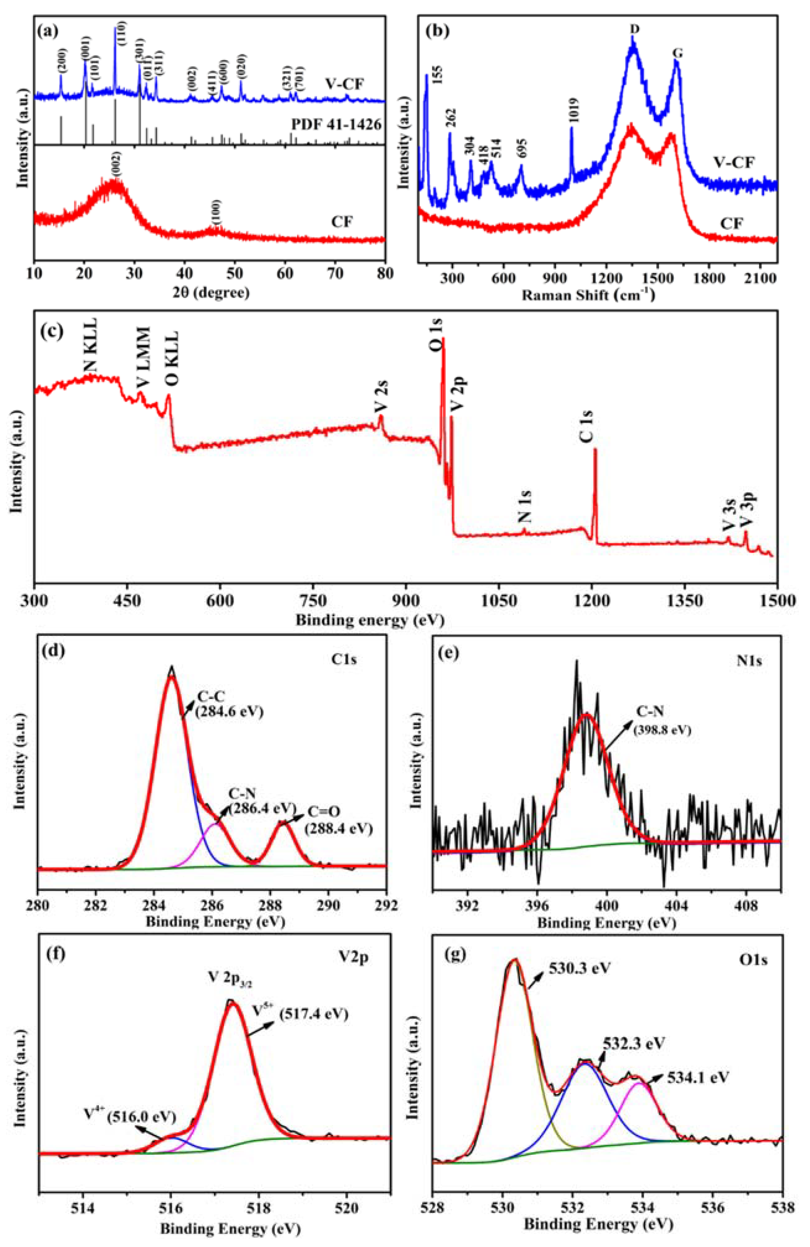
The XRD patterns and Raman spectra were collected to investigate the structure and composition of the CF and the V-CF samples (Figure 2). The standard diffraction pattern for the orthorhombic V2O5 (JCPDS Card No.: 41-1426, space group of Pmmn (59), a = 11.5 Å, b = 3.6 Å, and c = 4.4 Å) was also given as reference [51]. According to the XRD results, there were two broad peaks centered at around 25.0° and 43.2° for the CF, which can be indexed to the (002) and (100) diffractions of crystalline carbon [52,53]. For the V-CF, all the recorded XRD peaks can be assigned to the orthorhombic V2O5, without detections of any other vanadium oxides within the accuracy of measurements. Raman spectra further showed the existence of two broad modes centered at 1365 and 1595 cm−1 for the CF sample, which can be assigned to the D and G bands for carbon, respectively [54]. For the V-CF, Raman modes centered at 155, 262, 304, 418, 514, 695, and 1019 cm−1, were observed, which can be assigned to the orthorhombic phase V2O5 [55,56]. All these measurements indicated the formation of orthorhombic V2O5 and carbon in the V-CF. Moreover, X-ray photoelectron spectroscopy (XPS) was performed to investigate the chemical state of the V-CF (Figure 2c–f). Wide-range survey XPS spectrum suggested the existence of carbon, vanadium, oxygen, and nitrogen signals in the V-CF. The fitted pattern for the C1s spectrum indicated the existence of three different profiles of carbon with binding energies of 284.6, 286.4, and 288.4 eV, corresponding to the chemical bonds of C-C [57], C-N [58], and C=O [59], respectively. For the N1s spectrum, a binding energy of 398.8 eV, corresponding to the pyridinic-type N in carbon layer [60], was found, indicating the formation of N-doped carbon structure in the V-CF. Moreover, the fitted curves for the V2p spectrum (Figure 2e) indicated that there were two kinds of vanadium valence states with binding energies of 517.4 eV and 516.0 eV, respectively, which can be assigned to the dominant pentavalent vanadium bonds in V2O5 and small amount of V4+ defect in the sample [61,62,63,64]. For the O 1s spectrum (Figure 2g), three individual peaks, centered at 530.3, 532.3, and 534.1 eV, were found from the fitted XPS curves, which can be attributed to the binding energies of V-O-V in V2O5 [65], V-OH [66], and C-O [67], respectively. The latter two signals are probably components from the surface contaminating groups for V2O5 and carbon fibers.
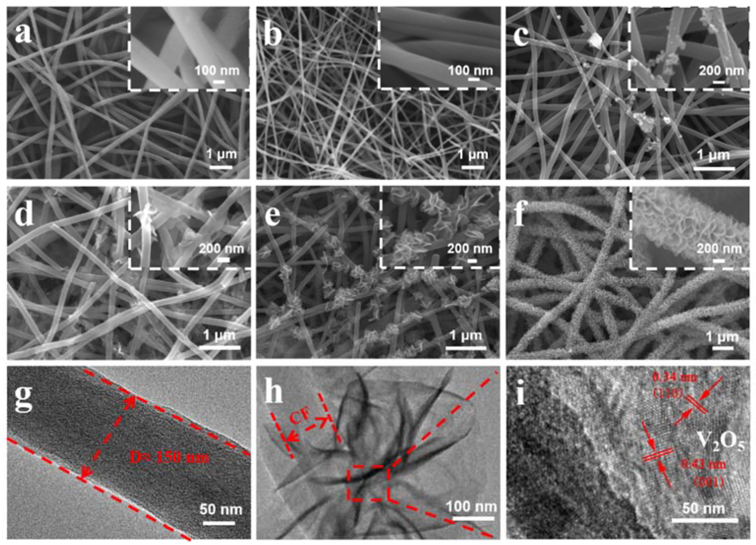
The morphologies and structure for the electrospun PAN, the carbonized PAN fibers (sample CF), and the V2O5 anchored carbon fibers (sample of V-CF) were characterized by SEM and TEM (Figure 3). The pristine electrospun PAN displayed quite porous structures with cross-linked thin fibers (diameter of 150–250 nm) (Figure 3a). After carbonization at 900 °C for 2 h, the main porous structures were retained, although the fiber diameter was shrunk slightly to be around 100–200 nm (Figure 3b). For the V-CF sample, after deposition of V2O5, a significant morphology change, especially on surfaces of the carbon fiber, was observed. A gradual evolution from small dots, to quasi-isolated nanoplates, and further, to uniformly assembled nanoplate arrays on the fibers, can be clearly recognized, with a prolonged hydrothermal treating time (Figure 3c–f). TEM (Figure 3g,h) and HRTEM (Figure 3i) further showed that these nanoplates can be assigned to orthorhombic V2O5, which were near-vertically grown on surfaces of the CF. This structure is quite different from the structure as reported in the study of Liu et al. [47], where uniform coating of V2O5 on the CF was obtained. However, this may derive from a varied hydrothermal condition and/or the different structures of carbon fiber applied. As per literatures, vanadium (V) oxytriisopropoxide can hydrolyze into vanadium oxytrihydroxide, which further nucleate and precipitate to form sheet-like V2O5·H2O (a reaction scheme is shown in Figure 1). The existence of surface functional groups or defects, such as the carbonyl group and the pyridinic-type N in carbon as confirmed in the XPS, can serve as effective nucleation centers for the growth of V2O5·H2O, [51] which can help induce the growth of sheet-like V2O5 on surfaces of the CF. Similar growth model of near-vertically aligned V2O5 nanoplates on carbon substrate were also reported from a similar hydrothermal condition, [68] which further supported our results for the growth of the 2D/1D V2O5 nanoplates on the CF structures for the V-CF. Moreover, it is worth noting that this special 2D/1D structure is expected to afford more promising benefits than the reported uniform thin V2O5 coating on the carbon fiber, which will be discussed in the following parts.
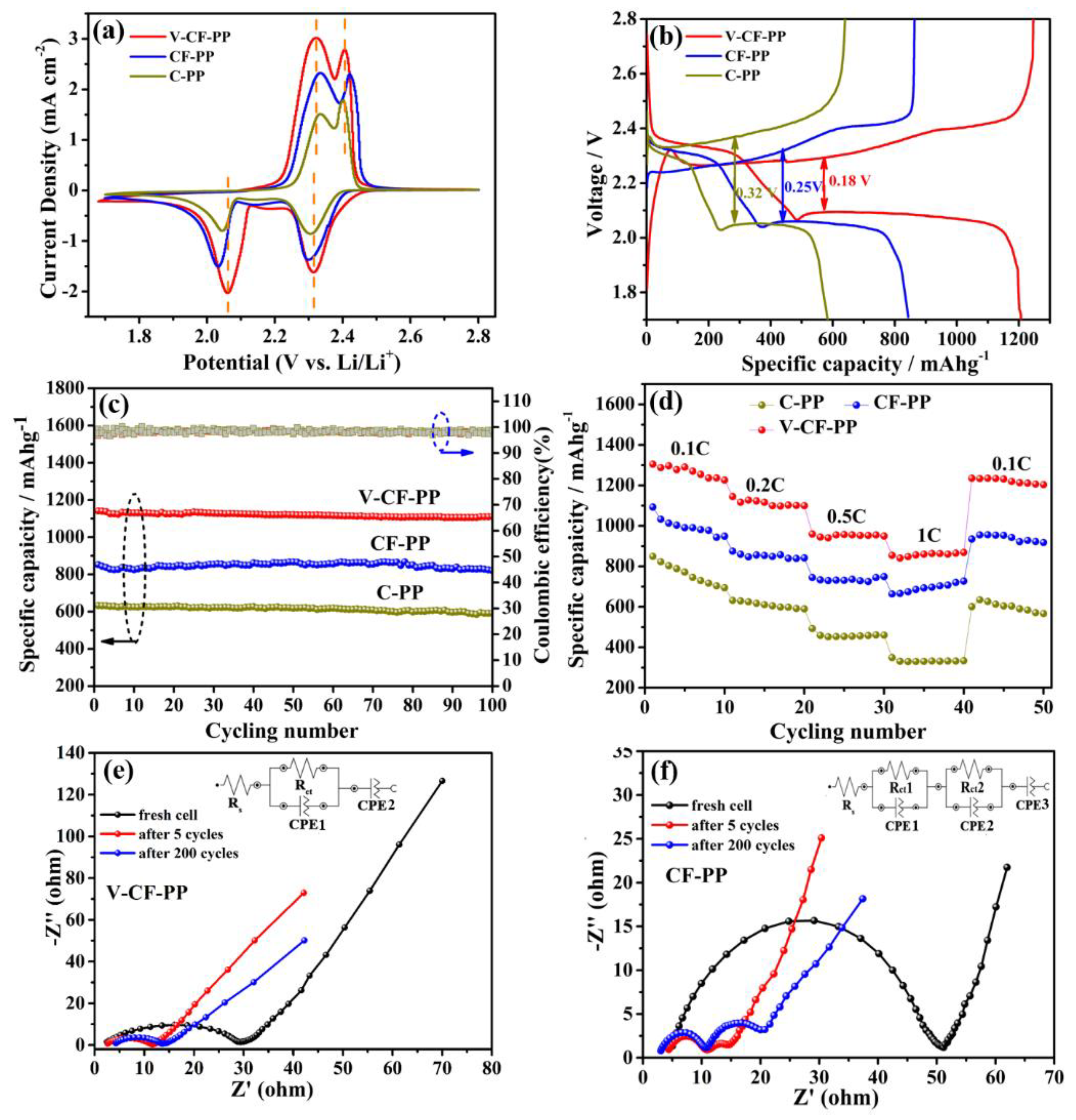
The electrochemical performances for lithium–sulfur batteries assembled with PP, CF modified PP, and V-CF modified PP as the separators, are shown in Figure 4. In the cyclic voltammetry (CV) curves (Figure 4a), two pairs of distinct redox peaks, indicating the reactions among sulfur (S8), long-chain lithium polysulfides (Li2Sx, 3 ≤ x ≤ 8), and the insoluble short-chain Li2S2/Li2S [69,70,71], were observed. Interestingly, at the high sulfur loading content of about 78.2 wt.% (see the TG result, Figure 5b) applied in our investigation, the V-CF-PP cell still showed a quite low polarization, with a voltage gap of only about 0.18 V. The recorded peak current for the V-CF-modified battery was also the highest among the three samples, indicating a significantly increased polysulfide redox kinetics. Figure 4c shows the cycling performance of the three Li–S batteries after charging/discharging for over 100 cycles at 0.2 C. In a detail, the C-PP cell showed an initial capacity of 632.3 mAh·g−1, which further decreased to be around 590.5 mAh·g−1 after 100 cycles; for batteries assembled with the V-CF-PP and CF-PP separators, high initial capacities of 1140.8 and 852.2 mAh·g−1, and excellent residual capacity of 1110.2 and 820.6 mAh·g−1 (corresponding to a loss of only 0.31 and 0.32 mAh·g−1 for each cycle) after 100 cycles, were delivered. These values, especially for the V2O5 deposited sample of V-CF-PP, were quite noteworthy among the reports for Li–S batteries. Rate performance, measured from 0.1 to 1 C (Figure 4d), also clearly showed the advantages of the V-CF-PP separator over the CF-PP or C-PP counterparts. In details, the specific discharge capacities of the V-CF-PP cell were 1268.2, 1112.9, 952.3, and 858.2 mAh·g−1, respectively, at current densities of 0.1, 0.2, 0.5, and 1 C. The corresponding capacity of the CF-PP and C-PP cells were only 997.6, 851.8, 735.6, and 693.8 mAh·g−1 and 762.6, 610.0, 460.2, and 333.2 mAh·g−1, respectively. When switched back to 0.1 C again, the V-CF-PP cells recovered about 96.2% of its initial capacity, indicating the stable and highly reversible properties of battery obtained by the V-CF separators.
Electrochemical impedance spectroscopy (EIS) analysis was also performed to investigate the charge-transferring properties for the CF-PP and the V-CF-PP, taken for the fresh cell, fully charged cell after 5 cycles, and after 200 cycles, respectively. We can see from the EIS plots that the impedance of the V-CF-PP and the CF-PP cells decreased after the first five cycles, due to the utilization of the conductive network after the redistribution of the active materials in interlayers and cathode induced by the shuttle phenomenon [72]. For the CF-PP cell, additional semicircle locating at the high frequency region (around 10–20 Ω) appeared in the Nyquist plot, which can be assigned to the formation of additional resistive phase (e.g., irreversible precipitates of solid Li2S and Li2S2) on the CF networks during cycling [73,74]. After long-term cycling for 200 times, the impedance for this part increased unwillingly, indicating an adverse accumulation of resistive phases that may block interfacial charge transferring. Correspondingly, for the V-CF-PP cell, a single charge-transfer resistance (around 2–10 Ω) was observed after 5 activation cycles, which still retained after 200 cycles of charging/discharging, indicating that the charge transfer across the electrode–electrolyte interfaces for the V-CF interlayer were quite stable. The inset images showed the equivalent circuits of the two samples, which were composed of the solution resistance (Rs), the charge-transfer resistance (Rct), and the double-layer capacitance (CPE). After long-term cycling for CF-PP cell, additional impedances, corresponding to Rct2 and CPE2, were introduced.
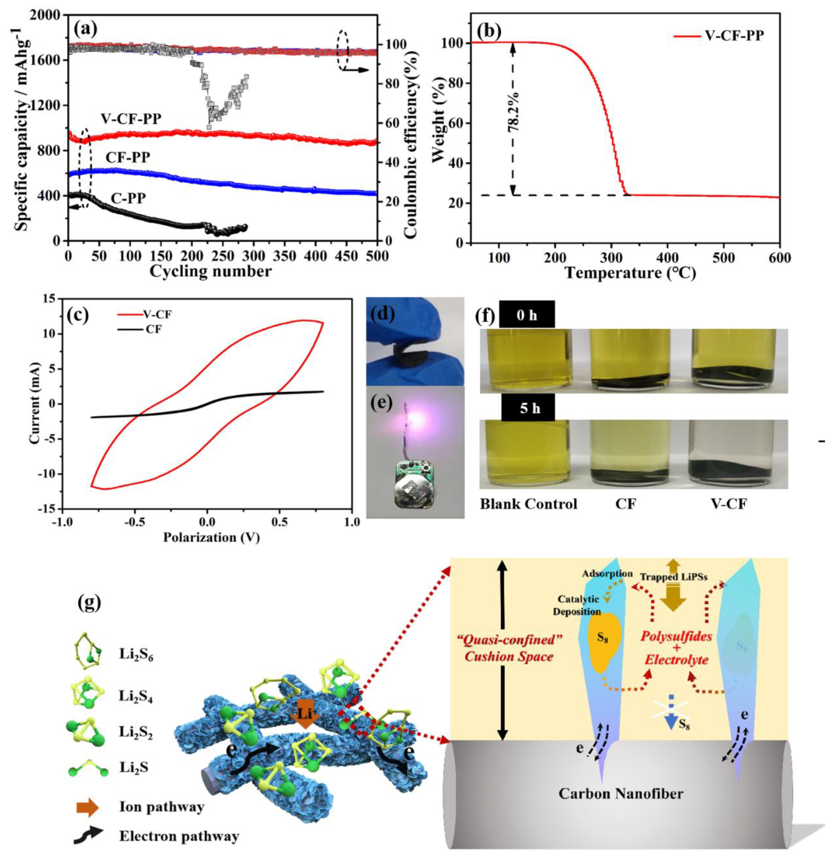
Long-term cycling at a higher charging and discharging rate of 1 C was performed to investigate the cycling stability for the three batteries (sulfur area loading amount of about 1.6 mg·cm−2) (Figure 5a). We can see from Figure 5a that the V-CF-PP cell delivered an initial capacity of 930.4 mAh·g−1 and a reversible capacity of 887.2 mAh·g−1 after 500 cycles (capacity retention rate of 95.4%), which are much better than the CF-PP and the C-PP cells. A purple LED powered by the V-CF-PP cell was also used (in Figure 5e), showing the practical potentials as portable power supply for LED lighting. The calculated decay rate was about 0.0093% per cycle for the V-CF-PP cell, which was an ultra-low value compared with literature-reported volumes, especially for different interlayers-modified lithium–sulfur batteries, e.g., 0.09% per cycle for mesoporous TiN (400 cycles at 1 C) [74], 0.083% per cycle for MoS2 nanosheets (600 cycles at 0.5 C) [75], and 0.07% per cycle for MTO-CNTs (500 cycles at 0.5 C) [76]. This high-capacity retention ability, especially the long-term stability at high charge–discharge rate, is expected to be originated from the special structures of 2D/1D V2O5 nanoplates on CF networks, which can serve as an effective quasi-confined cushion space (QCCS) that prompt the construction of stable electron/ion transportation pathway while maintaining excellent LiPSs interceptions. In addition, the V-CF membrane can be folded nearly in half (Figure 5d), demonstrating a good flexibility and mechanical toughness.
The schematic diagram for the V-CF interlayer-modified cell, Figure 5g, shows that there are several benefits for the specially aligned V2O5 2D structures on the conductive CF networks. First, the interconnected carbon fiber networks can provide effective electron conductivity that is helpful for high current density and fast redox kinetics. Second, as V2O5 is one of the high-adsorption-content materials for the LiPSs, [77] the vertically aligned V2O5 nanoplates on CF can further allow more adsorption sites to endorse LiPSs stabilization. The adsorption experiment in Figure 5f shows that, after 5 h immersion in the Li2S6 solution, the bottle containing V-CF appears almost transparent, while the others still show certain yellowish color. For the saturated adsorption test as described in the experimental section, a high saturated adsorption content of 35.2 μmol·cm−2 was obtained for the V-CF sample, which is much higher than the reported results of 22.3 μmol·cm−2 for V2O5 powders [78]. Third, catalytic-related contributions from the V2O5 should also be considered to improve the stability. Figure 5c shows the catalytic experiments conducted on symmetrical cells assembled with the CF and the V-CF electrodes, respectively. A significantly enhanced redox current for the V-CF symmetric cell than the bare CF control cell can be observed under a polarization from −0.8 to 0.8 V, which implied a higher catalytic property of V2O5 toward the LiPSs redox. In this case, a direct deposition of the solid-state sulfur species (e.g., S8 and Li2S) on V2O5 nanoplates, instead of forming them on the conductive carbon fibers, is expected, which can suppress the increasement of impedance during cycling.
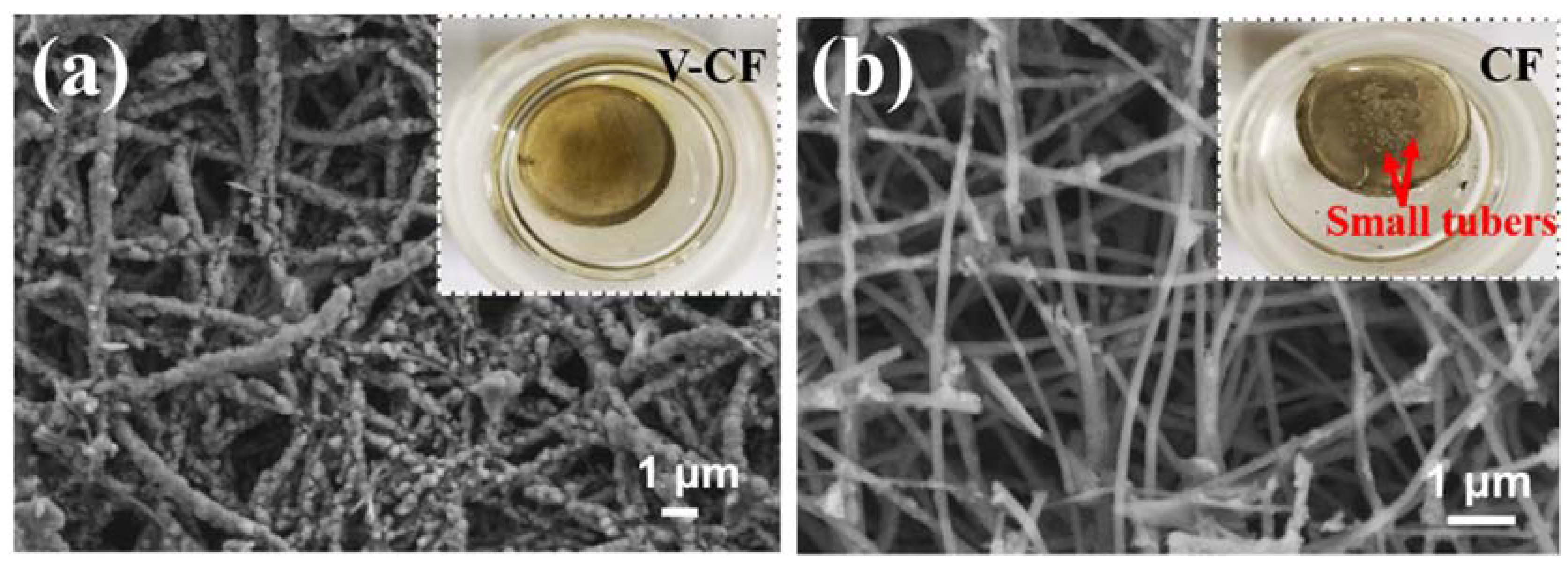
Moreover, after the formation of the soluble long-chained LiPSs from the first discharging cycle and their shuttling between the anode and the cathode in the electrolyte, more and more LiPSs will be adsorbed and stored into the QCCS on the surfaces of carbon fiber (Figure 5g). Because of the catalytic redox-related deposition and the large saturated adsorption content of the vertically aligned V2O5 nanoplates, most of the LiPSs compounds will be trapped inside the QCCS, which is especially favorable for building stable ion transportation pathways in Li–S batteries. SEM images for the detached interlayers from the V-CF and the CF cells after 100 cycles discharge and charge at 1 C were further employed to investigate their morphology evolution after long-term cycling. These results are shown in Figure 6. Figure 6 shows large amounts of sulfur species (most possibly in the form of S8 at the fully charge state) around the fibers in the V-CF interlayer, demonstrating the successful adsorption and storage of most LiPSs in the proposed QCCS; besides, a great many large pores can still be detected, indicating the preservation of abundant ion pathways after long cycle periods. While for the CF interlayer, only quite small amounts of sulfur species can be found on the carbon fibers due to their weak interactions with the LiPSs. Moreover, the insert in Figure 6 also shows the severe anode corrosions with many visible small tubers on lithium foil surface for the CF cell, which can be originated from the diffusion of soluble polysulfides that react with the lithium metal. In vivid contrast, the lithium anode in the V-CF cell exhibited a relatively uniform and smooth surface after cycling. All these investigations indicated the advantages of the architecture-derived enhancement on the electrochemical stability, by introducing near-vertically aligned V2O5 nanoplates on carbon fiber surfaces to form efficient interlayer for high-performance Li–S batteries.

4. Conclusions

In summary, a novel near-vertically aligned V2O5 nanoplates anchored carbon nanofiber interlayer was elaborately designed and synthesized, which showed significantly enhanced stability of electrochemical redox for Li–S batteries. Using the special V-CF composite structure, an effective “quasi-confined cushion space” that can flexibly accommodate the utilization of LiPSs and prompt the construction of stable electron/ion transportation pathway was demonstrated. For the Li–S battery assembled with the V-CF interlayer, a high initial capacity of 1140.8 mAh·g−1 and a stable reversed capacitance of 1110.2 mAh·g−1 after 100 cycles at 0.2 C were obtained. Additionally, a high reversible capacity of 887.2 mAh·g−1 and an ultra-low decay rate of 0.0093% per cycle after 500 cycles at 1 C were also kept, showing great potentials on improvements of the high rate and long cycling stability. The investigations may provide a novel structural-related protocol to address the power loss challenge for Li–S batteries.

Author Contributions

Z.Z. and Y.G. designed the experiment. G.W., H.J., and D.X. performed the main experiments. K.G., J.X., and B.M. performed the electrochemical measurements. Z.Z., Y.G., and L.K. designed the framework of the manuscript. G.W., D.X., Z.Z., H.J., and D.C. wrote the paper. L.Z., S.Y., Y.W., and Y.Z. provided some guidance for the experiment, and all authors participated in the discussion of the paper. All authors have read and agreed to the published version of the manuscript.

Funding

This study was supported in part by funding from the National Natural Science Foundation of China (NSFC, Contract Nos. 51502268, 51325203, and 51574205), the Excellent Young Teacher Development Foundation of Zhengzhou University (Contract No. 1421320050), and the Key Science and Technology Research Projects of Henan Provincial Education Department (Contract No. 14B430023).

Conflicts of Interest

The authors declare no conflicts of interest.

References

  1. Anasori, B.; Lukatskaya, M.R.; Gogotsi, Y. 2D metal carbides and nitrides (MXenes) for energy storage. Nat. Rev. Mater. 2017, 2, 16098. [Google Scholar] [CrossRef]
  2. Dong, C.; Gao, W.; Jin, B.; Jiang, Q. Advances in Cathode Materials for High-Performance Lithium-Sulfur Batteries. IScience 2018, 6, 151–198. [Google Scholar] [CrossRef] [PubMed] [Green Version]
  3. Benveniste, G.; Rallo, H.; Canals Casals, L.; Merino, A.; Amante, B. Comparison of the state of Lithium-Sulphur and lithium-ion batteries applied to electromobility. J. Environ. Manag. 2018, 226, 1–12. [Google Scholar] [CrossRef] [PubMed] [Green Version]
  4. Ding, B.; Yuan, C.; Shen, L.; Xu, G.; Nie, P.; Zhang, X. Encapsulating Sulfur into Hierarchically Ordered Porous Carbon as a High-Performance Cathode for Lithium–Sulfur Batteries. Chem. Eur. J. 2013, 19, 1013–1019. [Google Scholar] [CrossRef] [PubMed]
  5. Zhou, G.; Paek, E.; Hwang, G.S.; Manthiram, A. High-Performance Lithium-Sulfur Batteries with a Self-Supported, 3D Li2S-Doped Graphene Aerogel Cathodes. Adv. Energy Mater. 2016, 6, 1501355. [Google Scholar] [CrossRef]
  6. Zhou, G.; Yin, L.C.; Wang, D.W.; Li, L.; Pei, S.; Gentle, I.R.; Li, F.; Cheng, H.M. Fibrous Hybrid of Graphene and Sulfur Nanocrystals for High-Performance Lithium–Sulfur Batteries. ACS Nano 2013, 7, 5367–5375. [Google Scholar] [CrossRef]
  7. Zhou, M.G.; Lu, L.; Ma, C.Q.; Wang, S.G.; Shi, Y.; Koratkar, N.; Ren, W.C.; Li, F.; Cheng, H. A graphene foam electrode with high sulfur loading for flexible and high energy Li-S batteries. Nano Energy 2015, 11, 356–365. [Google Scholar] [CrossRef]
  8. Zhang, Z.W.; Peng, H.J.; Zhao, M.; Huang, J.Q. Heterogeneous/Homogeneous Mediators for High-Energy-Density Lithium–Sulfur Batteries: Progress and Prospects. Adv. Funct. Mater. 2018, 28, 1707536. [Google Scholar] [CrossRef]
  9. Zheng, G.; Yang, Y.; Cha, J.J.; Hong, S.S.; Cui, Y. Hollow Carbon Nanofiber-Encapsulated Sulfur Cathodes for High Specific Capacity Rechargeable Lithium Batteries. Nano Lett. 2011, 11, 4462–4467. [Google Scholar] [CrossRef]
  10. Zhang, J.; Yang, C.P.; Yin, Y.X.; Wan, L.J.; Guo, Y.G. Sulfur Encapsulated in Graphitic Carbon Nanocages for High-Rate and Long-Cycle Lithium–Sulfur Batteries. Adv. Mater. 2016, 28, 9539–9544. [Google Scholar] [CrossRef]
  11. Manthiram, A.; Fu, Y.; Chung, S.H.; Zu, C.; Su, Y.S. Rechargeable Lithium–Sulfur Batteries. Chem. Rev. 2014, 114, 11751–11787. [Google Scholar] [CrossRef] [PubMed]
  12. Manthiram, A.; Fu, Y.; Su, Y.S. Challenges and Prospects of Lithium–Sulfur Batteries. Acc. Chem. Res. 2013, 46, 1125–1134. [Google Scholar] [CrossRef]
  13. Li, Z.; Yuan, L.; Yi, Z.; Sun, Y.; Liu, Y.; Jiang, Y.; Shen, Y.; Xin, Y.; Zhang, Z.; Huang, Y. Insight into the Electrode Mechanism in Lithium-Sulfur Batteries with Ordered Microporous Carbon Confined Sulfur as the Cathode. Adv. Energy Mater. 2014, 4, 1301473. [Google Scholar] [CrossRef]
  14. Borchardt, L.; Oschatz, M.; Kaskel, S. Carbon Materials for Lithium Sulfur Batteries-Ten Critical Questions. Chem. Eur. J. 2016, 22, 7324–7351. [Google Scholar] [CrossRef] [PubMed]
  15. Qu, C.; Chen, Y.; Yang, X.; Zhang, H.; Li, X.; Zhang, H. LiNO3-free electrolyte for Li-S battery: A solvent of choice with low Ksp of polysulfide and low dendrite of lithium. Nano Energy 2017, 39, 262–272. [Google Scholar] [CrossRef]
  16. Tan, L.; Li, X.; Wang, Z.; Guo, H.; Wang, J. Lightweight Reduced Graphene Oxide@MoS2 Interlayer as Polysulfide Barrier for High-Performance Lithium–Sulfur Batteries. ACS Appl. Mater. Interfaces 2018, 10, 3707–3713. [Google Scholar] [CrossRef]
  17. Tang, H.; Yao, S.; Xue, S.; Liu, M.; Chen, L.; Jing, M.; Shen, X.; Li, T.; Xiao, K.; Qin, S. In-situ synthesis of carbon@Ti4O7 non-woven fabric as a multi-functional interlayer for excellent lithium-sulfur battery. Electrochim. Acta 2018, 263, 158–167. [Google Scholar] [CrossRef]
  18. Xin, S.; Gu, L.; Zhao, N.H.; Yin, Y.X.; Zhou, L.J.; Guo, Y.G.; Wan, L.J. Smaller Sulfur Molecules Promise Better Lithium–Sulfur Batteries. J. Am. Chem. Soc. 2012, 134, 18510–18513. [Google Scholar] [CrossRef]
  19. Yu, M.; Ma, J.; Song, H.; Wang, A.; Tian, F.; Wang, Y.; Qiu, H.; Wang, R. Atomic layer deposited TiO2 on a nitrogen-doped graphene/sulfur electrode for high performance lithium–sulfur batteries. Energy Environ. Sci. 2016, 9, 1495–1503. [Google Scholar] [CrossRef]
  20. Hou, T.Z.; Chen, X.; Peng, H.J.; Huang, J.Q.; Li, B.Q.; Zhang, Q.; Li, B. Design Principles for Heteroatom-Doped Nanocarbon to Achieve Strong Anchoring of Polysulfides for Lithium–Sulfur Batteries. Small 2016, 12, 3283–3291. [Google Scholar] [CrossRef]
  21. Ji, X.; Evers, S.; Black, R.; Nazar, L.F. Stabilizing lithium–sulphur cathodes using polysulphide reservoirs. Nat. Commun. 2011, 2, 325. [Google Scholar] [CrossRef] [PubMed] [Green Version]
  22. Zhang, K.L.; Chen, F.F.; Pan, H.P.; Wang, L.; Wang, D.; Jiang, Y.; Wang, L.B.; Qian, Y.T. Study on the effect of transition metal sulfide in lithium–sulfur battery. Inorg. Chem. Front. 2019, 6, 477–481. [Google Scholar] [CrossRef]
  23. Qian, W.; Gao, Q.; Zhang, H.; Tian, W.; Li, Z.; Tan, Y.L. Crosslinked Polypyrrole Grafted Reduced Graphene Oxide-Sulfur Nanocomposite Cathode for High Performance Li-S Battery. Electrochim. Acta 2017, 235, 32–41. [Google Scholar] [CrossRef]
  24. Hong, X.H.; Li, S.L.; Tang, X.N.; Sun, Z.H.; Li, F. Self-supporting porous CoS2/rGO sulfur host prepared by bottom-up assembly for lithium-sulfur batteries. J. Alloys Compd. 2018, 749, 586–593. [Google Scholar] [CrossRef]
  25. Luo, L.Y.; Qin, X.Y.; Wu, J.X.; Liang, G.M.; Li, Q.; Liu, M.; Kang, F.Y.; Chen, G.H.; Li, B.H. An interwoven MoO3@CNT scaffold interlayer for high-performance lithium–sulfur batteries. J. Mater. Chem. A 2018, 6, 8612–8619. [Google Scholar] [CrossRef]
  26. Wang, Z.S.; Shen, J.D.; Liu, J.; Xu, X.J.; Liu, Z.B.; Hu, R.Z.; Yang, L.C.; Feng, Y.Z.; Liu, J.; Shi, Z.C.; et al. Self-Supported and Flexible Sulfur Cathode Enabled via Synergistic Confinement for High-Energy-Density Lithium–Sulfur Batteries. Adv. Mater. 2019, 31, 1902228. [Google Scholar] [CrossRef]
  27. Bai, S.; Liu, X.; Zhu, K.; Wu, S.; Zhou, H. Metal–organic framework-based separator for lithium–sulfur batteries. Nat. Energy 2016, 1, 16094. [Google Scholar] [CrossRef]
  28. Guo, Y.; Zhang, Y.; Xiang, M.; Wu, H.; Liu, H.; Dou, S. Interwoven V2O5 nanowire/graphene nanoscroll hybrid assembled as efficient polysulfide-trapping-conversion interlayer for long-life lithium–sulfur batteries. J. Mater. Chem. A 2018, 6, 19358–19370. [Google Scholar] [CrossRef]
  29. Jeong, Y.C.; Kim, J.H.; Nam, S.; Park, C.R.; Yang, S.J. Rational Design of Nanostructured Functional Interlayer/Separator for Advanced Li–S Batteries. Adv. Funct. Mater. 2018, 28, 1707411. [Google Scholar] [CrossRef]
  30. Su, Y.S.; Manthiram, A. Lithium–sulphur batteries with a microporous carbon paper as a bifunctional interlayer. Nat. Commun. 2012, 3, 1166. [Google Scholar] [CrossRef] [Green Version]
  31. Schuster, J.; He, G.; Mandlmeier, B.; Yim, T.; Lee, K.T.; Bein, T.; Nazar, L.F. Spherical Ordered Mesoporous Carbon Nanoparticles with High Porosity for Lithium–Sulfur Batteries. Angew. Chem. Int. Ed. 2012, 51, 3591–3595. [Google Scholar] [CrossRef] [PubMed]
  32. Song, J.; Xu, T.; Gordin, M.L.; Zhu, P.; Lv, D.; Jiang, Y.B.; Chen, Y.; Duan, Y.; Wang, D. Nitrogen-Doped Mesoporous Carbon Promoted Chemical Adsorption of Sulfur and Fabrication of High-Areal-Capacity Sulfur Cathode with Exceptional Cycling Stability for Lithium-Sulfur Batteries. Adv. Funct. Mater. 2014, 24, 1243–1250. [Google Scholar] [CrossRef]
  33. Xiao, Z.; Yang, Z.; Wang, L.; Nie, H.; Zhong, M.E.; Lai, Q.; Xu, X.; Zhang, L.; Huang, S. A Lightweight TiO2/Graphene Interlayer, Applied as a Highly Effective Polysulfide Absorbent for Fast, Long-Life Lithium–Sulfur Batteries. Adv. Mater. 2015, 27, 2891–2898. [Google Scholar] [CrossRef] [PubMed]
  34. Tan, S.; Yang, Z.; Yuan, H.; Zhang, J.; Yang, Y.; Liu, H. MnO2-decorated graphene aerogel with dual-polymer interpenetrating network as an efficient hybrid host for Li-S batteries. J. Alloys Compd. 2019, 791, 483–489. [Google Scholar] [CrossRef]
  35. Liu, Y.; Qin, X.; Zhang, S.; Liang, G.; Kang, F.; Chen, G.; Li, B. Fe3O4-Decorated Porous Graphene Interlayer for High-Performance Lithium–Sulfur Batteries. ACS Appl. Mater. Interfaces 2018, 10, 26264–26273. [Google Scholar] [CrossRef]
  36. An, Q.; Zhang, P.; Xiong, F.; Wei, Q.; Sheng, J.; Wang, Q.; Mai, L. Three-dimensional porous V2O5 hierarchical octahedrons with adjustable pore architectures for long-life lithium batteries. Nano Res. 2015, 8, 481–490. [Google Scholar] [CrossRef]
  37. Shao, J.; Li, X.; Wan, Z.; Zhang, L.; Ding, Y.; Zhang, L.; Qu, Q.; Zheng, H. Low-Cost Synthesis of Hierarchical V2O5 Microspheres as High-Performance Cathode for Lithium-Ion Batteries. ACS Appl. Mater. Interfaces 2013, 5, 7671–7675. [Google Scholar] [CrossRef]
  38. Song, H.; Liu, C.; Zhang, C.; Cao, G. Self-doped V4+–V2O5 nanoflake for 2 Li-ion intercalations with enhanced rate and cycling performance. Nano Energy 2016, 22, 1–10. [Google Scholar] [CrossRef]
  39. Chou, S.L.; Wang, J.Z.; Sun, J.Z.; Wexler, D.; Forsyth, M.; Liu, H.K.; MacFarlane, D.R.; Dou, S.X. High Capacity, Safety, and Enhanced Cyclability of Lithium Metal Battery Using a V2O5 Nanomaterial Cathode and Room Temperature Ionic Liquid Electrolyte. Chem. Mater. 2008, 20, 7044–7051. [Google Scholar] [CrossRef]
  40. Ng, S.H.; Patey, T.J.; Büchel, R.; Krumeich, F.; Wang, J.Z.; Liu, H.K.; Pratsinis, S.E.; Novák, P. Flame spray-pyrolyzed vanadium oxide nanoparticles for lithium battery cathodes. Phys. Chem. Chem. Phys. 2009, 11, 3748–3755. [Google Scholar] [CrossRef] [Green Version]
  41. Ragupathy, P.; Shivakumara, S.; Vasan, H.N.; Munichandraiah, N. Preparation of Nanostrip V2O5 by the Polyol Method and Its Electrochemical Characterization as Cathode Material for Rechargeable Lithium Batteries. J. Phys. Chem. C 2008, 112, 16700–16707. [Google Scholar] [CrossRef]
  42. Sun, B.; Huang, K.; Qi, X.; Wei, X.; Zhong, J. Rational Construction of a Functionalized V2O5 Nanosphere/MWCNT Layer-by-Layer Nanoarchitecture as Cathode for Enhanced Performance of Lithium-Ion Batteries. Adv. Funct. Mater. 2015, 25, 5633–5639. [Google Scholar] [CrossRef]
  43. Kim, M.S.; Shin, E.S.; Kim, J.S.; Cho, W.I.; Oh, S.H. The effect of V2O5/C additive on the suppression of polysulfide dissolution in Li-sulfur batteries. J. Electroceram. 2014, 33, 142–148. [Google Scholar] [CrossRef]
  44. Liang, X.; Kwok, C.Y.; Lodi-Marzano, F.; Pang, Q.; Cuisinier, M.; Huang, H.; Hart, C.J.; Houtarde, D.; Kaup, K.; Sommer, H.; et al. Tuning Transition Metal Oxide–Sulfur Interactions for Long Life Lithium Sulfur Batteries: The “Goldilocks” Principle. Adv. Energy Mater. 2016, 6, 1501636. [Google Scholar] [CrossRef]
  45. Zhang, Q.; Wang, Y.; She, Z.W.; Fu, Z.; Zhang, R.; Cui, Y. Understanding the Anchoring Effect of Two-Dimensional Layered Materials for Lithium–Sulfur Batteries. Nano Lett. 2015, 15, 3780–3786. [Google Scholar] [CrossRef]
  46. Guan, B.; Zhang, Y.; Fan, L.; Wu, X.; Wang, M.; Qiu, Y.; Zhang, N.; Sun, K. Blocking Polysulfide with Co2B@CNT via “Synergetic Adsorptive Effect” toward Ultrahigh-Rate Capability and Robust Lithium–Sulfur Battery. ACS Nano 2019, 13, 6742–6750. [Google Scholar] [CrossRef]
  47. Liu, M.; Li, Q.; Qin, X.; Liang, G.; Han, W.; Zhou, D.; He, Y.B.; Li, B.; Kang, F. Suppressing Self-Discharge and Shuttle Effect of Lithium–Sulfur Batteries with V2O5-Decorated Carbon Nanofiber Interlayer. Small 2017, 13, 1602539. [Google Scholar] [CrossRef]
  48. Saravanakumar, B.; Purushothaman, K.K.; Muralidharan, G. V2O5/functionalized MWCNT hybrid nanocomposite: The fabrication and its enhanced supercapacitive performance. RSC Adv. 2014, 4, 37437–37445. [Google Scholar] [CrossRef]
  49. Wu, L.; Zhang, Y.; Li, B.; Wang, P.; Fan, L.; Zhang, N.; Sun, K. N doped carbon coated V2O5 nanobelt arrays growing on carbon cloth toward enhanced performance cathodes for lithium ion batteries. RSC Adv. 2018, 8, 6540–6543. [Google Scholar] [CrossRef] [Green Version]
  50. Wu, Y.; Gao, M.; Li, X.; Liu, Y.; Pan, H. Preparation of mesohollow and microporous carbon nanofiber and its application in cathode material for lithium–sulfur batteries. J. Alloys Compd. 2014, 608, 220–228. [Google Scholar] [CrossRef]
  51. Cheng, J.; Wang, B.; Xin, H.L.; Yang, G.; Cai, H.; Nie, F.; Huang, H. Self-assembled V2O5 nanosheets/reduced graphene oxide hierarchical nanocomposite as a high-performance cathode material for lithium ion batteries. J. Mater. Chem. A 2013, 1, 10814–10820. [Google Scholar] [CrossRef]
  52. Li, W.; Chen, Z.; Li, J.; Chen, X.; Xuan, H.; Wang, X. Preparation of PAN/phenolic-based carbon/carbon composites with flexible towpreg carbon fiber. Mater. Sci. Eng. A 2008, 485, 481–486. [Google Scholar] [CrossRef]
  53. Xia, D.; Quan, J.; Wu, G.; Liu, X.; Zhang, Z.; Ji, H.; Chen, D.; Zhang, L.; Wang, Y.; Yi, S.; et al. Linear-Polyethyleneimine-Templated Synthesis of N-Doped Carbon Nanonet Flakes for High-performance Supercapacitor Electrodes. Nanomaterials 2019, 9, 1225. [Google Scholar] [CrossRef] [PubMed] [Green Version]
  54. Minamisawa, T.; Oshida, K.; Kobayashi, N.; Ando, A.; Misawa, D.; Itaya, T.; Moriyama, M.; Osawa, K.; Hata, T.; Sugiyama, Y.; et al. Development of Electrode Materials of Lithium-Ion Battery Utilizing Nanospaces. C J. Carbon Res. 2018, 4, 23. [Google Scholar] [CrossRef] [Green Version]
  55. Carter, R.; Oakes, L.; Muralidharan, N.; Cohn, A.P.; Douglas, A.; Pint, C.L. Polysulfide Anchoring Mechanism Revealed by Atomic Layer Deposition of V2O5 and Sulfur-Filled Carbon Nanotubes for Lithium–Sulfur Batteries. ACS Appl. Mater. Interfaces 2017, 9, 7185–7192. [Google Scholar] [CrossRef]
  56. Ghosh, A.; Ra, E.J.; Jin, M.; Jeong, H.K.; Kim, T.H.; Biswas, C.; Lee, Y.H. High Pseudocapacitance from Ultrathin V2O5 Films Electrodeposited on Self-Standing Carbon-Nanofiber Paper. Adv. Funct. Mater. 2011, 21, 2541–2547. [Google Scholar] [CrossRef]
  57. Wang, Y.X.; Li, Y.J.; Yang, H.; Xu, Z.L. Super-wetting, photoactive TiO2 coating on amino-silane modified PAN nanofiber membranes for highly efficient oil-water emulsion separation application. J. Membr. Sci. 2019, 580, 40–48. [Google Scholar] [CrossRef]
  58. Kalybekkyzy, S.; Mentbayeva, A.; Kahraman, M.; Zhang, Y.; Bakenov, Z. Flexible S/DpAN/KB nanofiber composite as binder-free cathodes for Li-S batteries. J. Electrochem. Soc. 2019, 166, A5396–A5402. [Google Scholar] [CrossRef]
  59. Shi, Y.; Yang, D.; Li, Y.; Qu, J.; Yu, Z.Z. Fabrication of PAN@TiO2/Ag nanofibrous membrane with high visible light response and satisfactory recyclability for dye photocatalytic degradation. Appl. Surf. Sci. 2017, 426, 622–629. [Google Scholar] [CrossRef]
  60. Zhu, H.; Du, M.; Zhang, M.; Zou, M.; Yang, T.; Fu, Y.; Yao, J. The design and construction of 3D rose-petal-shaped MoS2 hierarchical nanostructures with structure-sensitive properties. J. Mater. Chem. A 2014, 2, 7680–7685. [Google Scholar] [CrossRef]
  61. Yao, Y.J.; Zhao, Q.; Wei, W.; Chen, Z.; Zhu, Y.; Zhang, P.; Zhang, Z.T.; Gao, Y.F. WO3 quantum-dots electrochromism. Nano Energy 2020, 68, 104350. [Google Scholar] [CrossRef]
  62. Zhou, Y.; Ramanathan, S. Heteroepitaxial VO2 thin films on GaN: Structure and metal-insulator transition characteristics. J. Appl. Phys. 2012, 112, 4621–4628. [Google Scholar] [CrossRef]
  63. Zhang, Z.; Feng, Y.; Gao, Y.F.; Chen, D.L.; Shao, G.S. Large Scale Synthesis of Nanopyramidal-Like VO2 Films by an Oxygen-Assisted Etching Growth Method with Significantly Enhanced Field Emission Properties. Nanomaterials 2019, 9, 549. [Google Scholar] [CrossRef] [PubMed] [Green Version]
  64. Zhou, J.D.; Gao, Y.F.; Zhang, Z.T.; Luo, H.J.; Cao, C.X.; Chen, Z.; Dai, L.; Liu, X.L. VO2 thermochromic smart window for energy savings and generation. Sci. Rep. 2013, 3, 3029. [Google Scholar] [CrossRef] [PubMed]
  65. Li, Z.L.; Zhu, Q.Y.; Huang, S.N.; Jiang, S.S.; Lu, S.; Chen, W.; Zakharova, G.S. Interpenetrating Network of V2O5 Nanosheets/Carbon Nanotubes Nanocomposite for Fast Lithium Storage. RSC Adv. 2014, 4, 46624–46630. [Google Scholar] [CrossRef]
  66. Sathiya, M.; Prakash, A.S.; Ramesha, K.; Tarascon, J.M.; Shukla, A.K. V2O5-Anchored Carbon Nanotubes for Enhanced Electrochemical Energy Storage. J. Am. Chem. Soc. 2011, 133, 16291. [Google Scholar] [CrossRef]
  67. Ren, Q.Y.; Qin, N.; Liu, B.; Yao, Y.; Zhao, X.; Deng, Z.; Li, Y.; Dong, Y.C.; Qian, D.; Su, B.L.; et al. An Oxygen-Deficient Vanadium Oxide@N-doped Carbon Heterostructure for Sodium-Ion Batteries: Insights into the Charge Storage Mechanism and Enhanced Reaction Kinetics. J. Mater. Chem. A 2020, 8, 3450. [Google Scholar] [CrossRef]
  68. Yu, R.; Zhang, C.; Meng, Q.; Chen, Z.; Liu, H.; Guo, Z. Facile Synthesis of Hierarchical Networks Composed of Highly Interconnected V2O5 Nanosheets Assembled on Carbon Nanotubes and Their Superior Lithium Storage Properties. ACS Appl. Mater. Interfaces 2013, 5, 12394–12399. [Google Scholar] [CrossRef] [Green Version]
  69. Li, Z.; He, Q.; Xu, X.; Zhao, Y.; Liu, X.; Zhou, C.; Ai, D.; Xia, L.; Mai, L. A 3D Nitrogen-Doped Graphene/TiN Nanowires Composite as a Strong Polysulfide Anchor for Lithium–Sulfur Batteries with Enhanced Rate Performance and High Areal Capacity. Adv. Mater. 2018, 30, 1804089. [Google Scholar] [CrossRef]
  70. Li, Z.; Yuan, L.; Yi, Z.; Liu, Y.; Xin, Y.; Zhang, Z.; Huang, Y. A dual coaxial nanocable sulfur composite for high-rate lithium–sulfur batteries. Nanoscale 2014, 6, 1653–1660. [Google Scholar] [CrossRef] [Green Version]
  71. Papandrea, B.; Xu, X.; Xu, Y.; Chen, C.Y.; Lin, Z.; Wang, G.; Luo, Y.; Liu, M.; Huang, Y.; Mai, L.; et al. Three-dimensional graphene framework with ultra-high sulfur content for a robust lithium–sulfur battery. Nano Res. 2016, 9, 240–248. [Google Scholar] [CrossRef]
  72. Peng, H.J.; Wang, D.W.; Huang, J.Q.; Cheng, X.B.; Yuan, Z.; Wei, F.; Zhang, Q. Janus Separator of Polypropylene-Supported Cellular Graphene Framework for Sulfur Cathodes with High Utilization in Lithium–Sulfur Batteries. Adv. Sci. 2016, 3, 1500268. [Google Scholar] [CrossRef] [PubMed]
  73. Li, Z.; Jiang, Q.; Ma, Z.; Liu, Q.; Wu, Z.; Wang, S. Oxygen plasma modified separator for lithium sulfur battery. RSC Adv. 2015, 5, 79473–79478. [Google Scholar] [CrossRef]
  74. Qi, B.; Zhao, X.S.; Wang, S.G.; Chen, K.; Wei, Y.J.; Chen, G.; Gao, Y.; Zhang, D.; Sun, Z.H.; Li, F. Mesoporous TiN microspheres as an efficient polysulfide barrier for lithium-sulfur batteries. J. Mater. Chem. A 2018, 6, 14359–14366. [Google Scholar] [CrossRef]
  75. Ghazi, Z.A.; He, X.; Khattak, A.M.; Khan, N.A.; Liang, B.; Iqbal, A.; Wang, J.X.; Sin, H.S.; Li, L.S.; Tang, Z.Y. MoS2/Celgard Separator as Efficient Polysulfide Barrier for Long-Life Lithium-Sulfur Batteries. Adv Mater. 2017, 29, 1606817. [Google Scholar] [CrossRef]
  76. Li, N.; Chen, Z.X.; Chen, F.; Hu, G.J.; Wang, S.G.; Sun, Z.H.; Sun, X.D.; Li, F. From interlayer to lightweight capping layer: Rational design of mesoporous TiO2 threaded with CNTs for advanced Li-S batteries. Carbon 2019, 143, 523–530. [Google Scholar] [CrossRef]
  77. Liu, F.; Xiao, Q.F.; Wu, H.B.; Sun, F.; Liu, X.Y.; Li, Y.; Le, Z.Y.; Shen, L.; Wang, G.; Cai, M.; et al. Regenerative Polysulfide-Scavenging Layers Enabling Lithium–Sulfur Batteries with High Energy Density and Prolonged Cycling Life. ACS Nano 2017, 11, 2697–2705. [Google Scholar] [CrossRef]
  78. Wu, D.S.; Shi, F.; Zhou, G.; Zu, C.; Liu, C.; Liu, K.; Liu, Y.; Wang, J.; Peng, Y.; Cui, Y. Quantitative investigation of polysulfide adsorption capability of candidate materials for Li-S batteries. Energy Storage Mater. 2018, 13, 241–246. [Google Scholar] [CrossRef]
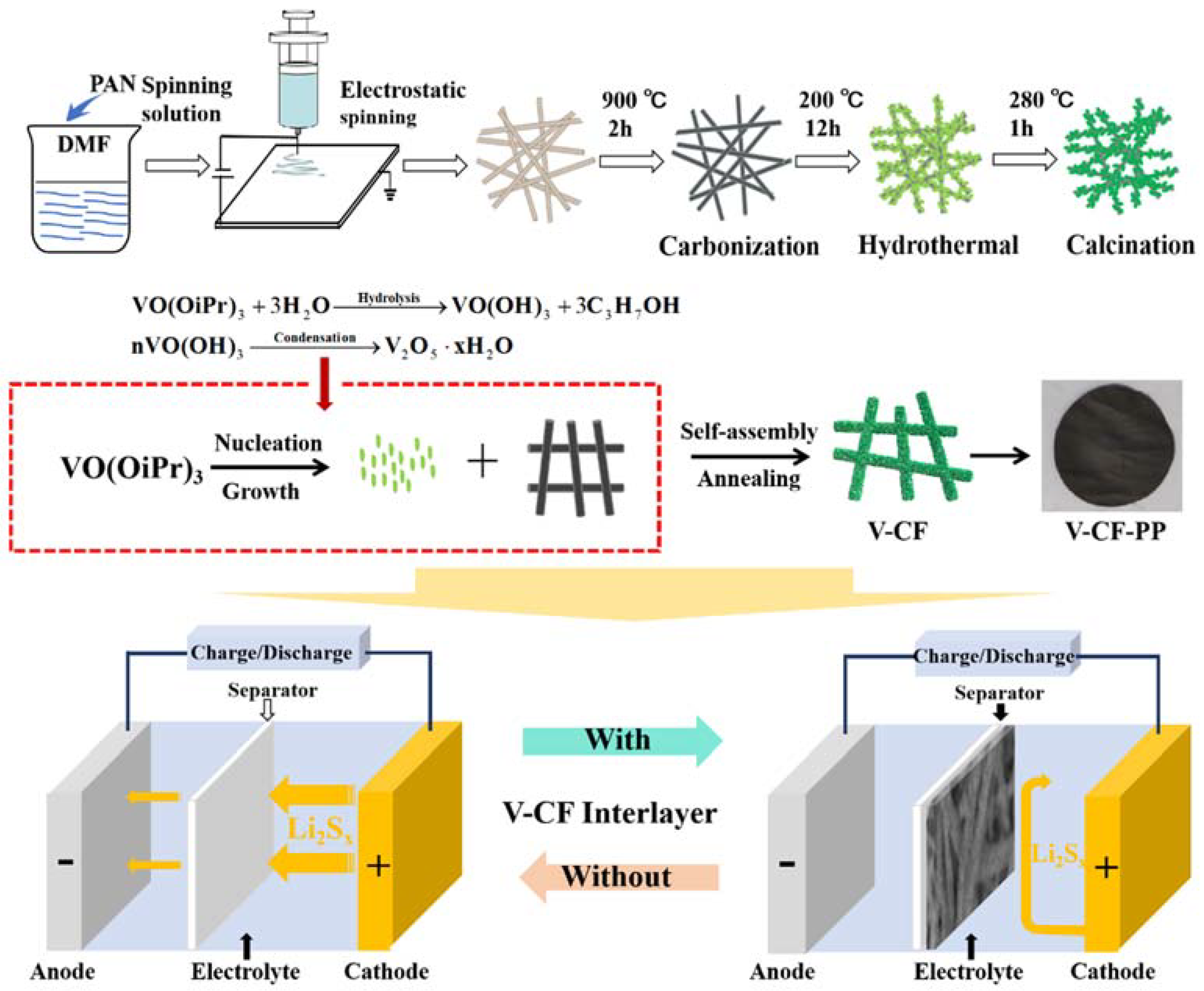
Figure 1. Schematic diagram for the synthesis of 2D/1D V2O5 nanoplates anchored carbon nanofiber (V-CF) composite interlayer. A photograph of the V-CF interlayer coated on polypropylene (PP) separator is also shown. The bottom two figures show the schematic configurations of the Li−S cells with (right figure) and without (left figure) the V-CF separator interlayer.
Nanomaterials 10 00705 g001
Figure 2. XRD patterns (a) and Raman spectra (b) of the carbon nanofiber (CF) and the V-CF. XPS wide-range survey spectrum (c) and the high-resolution XPS spectra of C 1s (d), V 2p (e), N 1s (f), and O 1s (g) for the sample of V-CF.
Nanomaterials 10 00705 g002
Figure 3. SEM images of the precursor polyacrylonitrile (PAN) fibers before (a) and after (b) carbonization. Figure (c)–(f) shows the SEM images for the CF membrane hydrothermally treated at 200 °C for 1, 4, 8, and 12 h, respectively. (The inset of each figure shows the corresponding high magnification images). (g) shows the TEM image for CF sample, and (h) and (i) are the TEM and HRTEM images, respectively, for the V-CF.
Nanomaterials 10 00705 g003
Figure 4. Electrochemical characterizations for the assembled batteries with PP, CF modified PP, and V-CF modified PP as the separators. (a) The second cycle cyclic voltammetry (CV) curves measured at a scan rate of 0.1 mV·s−1. (b) The charge/discharge profiles measured at a current rate of 0.2 C. (c) The capacity and coulombic efficiencies versus the cycle numbers measured at a current rate of 0.2 C. (d) The rate performance for different cells measured at 0.1, 0.2, 0.5, and 1 C, respectively. (e) and (f) are the electrochemical impedance spectroscopy (EIS) plots for the CF-PP and the V-CF-PP cells, respectively, measured at different cycles. (The inset of figure shows the equivalent circuit diagram of the CF-PP and V-CF-PP after 200 cycles.).
Nanomaterials 10 00705 g004
Figure 5. (a) Long-term cycling performance at 1 C for different batteries, (b) thermogravimetric (TG) analysis of the sulfur loadings in CF/S cathodes, (c) CV of symmetric cells using the CF and the V-CF membranes as the corresponding symmetric electrodes, (d) the flexibility test of the V-CF interlayer, (e) V-CF-PP battery lighting the diode, (f) photographs show the adsorption of Li2S6 in 1 M LiTFSI of 1,3-dioxolane (DOL)/dimethoxyethane (DME) electrolyte solution, and (g) the illustration for the cycling stability derived from a quasi-confined cushion space in the V-CF interlayer.
Nanomaterials 10 00705 g005
Figure 6. SEM of the V-CF (a) and the CF (b) interlayers after 100 cycles. Insert in each figure shows the photographs of the corresponding lithium electrode after 100 cycles at 1 C. The metallic lithium electrodes for both samples are immediately immersed into a mixture of DOL and DME for photograph observation.
Nanomaterials 10 00705 g006