Review

Yolk–Shell Nanostructures: Syntheses and Applications for Lithium-Ion Battery Anodes

Dongnam Regional Division, Korea Institute of Industrial Technology, Busan 46938, Korea
Nanomaterials 2020, 10(4), 675; https://doi.org/10.3390/nano10040675
Submission received: 6 March 2020 / Revised: 25 March 2020 / Accepted: 2 April 2020 / Published: 3 April 2020
(This article belongs to the Special Issue Novel Nanomaterials for Applications in Energy and Catalysis)

Abstract

:
Yolk–shell nanostructures have attracted tremendous research interest due to their physicochemical properties and unique morphological features stemming from a movable core within a hollow shell. The structural potential for tuning inner space is the focal point of the yolk–shell nanostructures in a way that they can solve the long-lasted problem such as volume expansion and deterioration of lithium-ion battery electrodes. This review gives a comprehensive overview of the design, synthesis, and battery anode applications of yolk–shell nanostructures. The synthetic strategies for yolk–shell nanostructures consist of two categories: templating and self-templating methods. While the templating approach is straightforward in a way that the inner void is formed by removing the sacrificial layer, the self-templating methods cover various different strategies including galvanic replacement, Kirkendall effect, Ostwald ripening, partial removal of core, core injection, core contraction, and surface-protected etching. The battery anode applications of yolk–shell nanostructures are discussed by dividing into alloying and conversion types with details on the synthetic strategies. A successful design of yolk–shell nanostructures battery anodes achieved the improved reversible capacity compared to their bare morphologies (e.g., no capacity retention in 300 cycles for Si@C yolk–shell vs. capacity fading in 10 cycles for Si@C core–shell). This review ends with a summary and concluding remark yolk–shell nanostructures.

1. Introduction

Energy storage from renewable energy production to electrical energy upgrades the status of lithium-ion batteries to a more significant position due to its large capacity, long lifespan, and high energy density [1]. Among the configuration of rechargeable batteries, the anode is an important part in lithium/sodium-ion batteries in terms of the following requirements: 1) high specific surface area for higher lithium/sodium ion insertion channels, 2) low volume change during charge/discharge for good cycling stability and safety, 3) large pore size and short path for high rate capability, 4) low internal resistance for fast charging, 5) low intercalation potential for Li or Na, 6) price competitiveness, and 7) environmentally-friendliness [2,3,4]. Since the commercial use of graphite as anode material in LIB, its low gravimetric capacity (graphite, 372 mAh/g) provoked the exponentially-increasing R&D needs for high capacity anode materials to meet the requirement of high energy density lithium-ion batteries for electrical vehicles, smart grid systems, and aerospace applications. An urgency to replace the conventional graphite anodes focused research efforts into lithium metal with higher energy density. Even though lithium metal has one of the highest capacities and the lowest potential, safety issues keep the use of lithium as anode material in LIB due to dendrite formation on lithium metal leading to short-circuit. Thus, alternative candidates have been emerging as new anode materials to tackle the safety problem. Based on the way of Li-ion storage, anode materials are classified into alloying anodes (Si, Sn, Ge, Al, SnO2), intercalating anodes (carbon, TiO2, LTO), and conversion reaction anodes (transition metal oxides, chalcogenides, phosphides, nitrides).
Compared to bulk silicon anode, nanoscale silicon materials have been demonstrated as an effective strategy since nanostructured Si can accommodate elevated mechanical stress leading to prolonged cycling stability. Nevertheless, such nanostructured Si anodes still suffer from short cycle life due to the loss of active material and increased cell impedance at high mass loading [5,6]. Other alloy-based anode materials, such as Sn and Ge, have long been considered as alternatives due to their high specific capacities and lower operating potentials than graphite. In addition, tin has low electrical resistivity (1.1 × 10⁻⁷ Ω·m). Tin and germanium are also prone to severe capacity degradation and short cycle life, caused by their large volume changes during lithiation/delithiation, subsequent pulverization, the formation of SEI, inhibition of Li+/electron transport, and delamination from current collector [7,8]. Metal oxides are also a promising family of anode materials since they have a safer lithiation potential that eliminates the problematic lithium dendrite formation during charging. However, the low electrical conductivity of metal oxides demands the conductive material in anode structures. Nanostructured metal oxides and their composites with various carbon materials have been used to improve their capacity retention by suppressing phase segregation, volumetric expansion, and ionic/electronic transport [9]. There have been recent research efforts to develop other anode materials including metal chalcogenides, phosphides, and nitrides. Like other transitional metal oxides, these metal compound anodes are based on the conversion reaction. Although these metal compounds have higher operating potential than graphite, they are still attractive candidates due to higher theoretical capacities [2,10,11,12,13,14].
Unlike the intercalating-type anodes with ignorable volume expansion, the chemical reaction between the anode with lithium ions accompanies serious volume change leading to an increase of internal resistance and rapid capacity decay. Due to the large volume change during charging/discharging in the anode, there needs to protect active material from fracture or dendrite formation. A number of structures have also been investigated in order to boost the capacity of lithium/sodium-ion batteries [15,16]. As one of the successful ways, researchers have paid attention on designing yolk–shell nanostructure to place active anode materials in hollow protecting layers [17,18,19,20]. Various research has already been done on the yolk–shell nanostructures for applications of drug delivery, sensor, and catalyst [21,22,23,24]. Different from core–shell structure in dense contact, yolk–shell nanostructures create movable space inside the protecting shell, which enables anode to expand without fragmentation or dendrite formation during a chemical reaction. Thus, yolk–shell nanostructures are beneficial for improving electrochemical performance owing to various merits including buffering space, large surface area, and short diffusion path.
In this review, we will provide a recent progress of battery anode materials based on yolk–shell nanostructures. For the starter, we give a general explanation on the development of how to build up yolk–shell nanostructures through templating and self-templating approaches. Then, we move on to discuss various yolk–shell nanostructures for application in lithium-ion battery anodes. Lastly, the concluding remark follows in the conclusion and outlook.

2. Building Yolk–Shell Nanostructure

Yolk–shell nanostructures indicate a class of hybrid materials consisting of a hollow shell encircling movable cores with the void. The hollow nanostructures containing different nanoparticles inside possess unique morphological features, which bring low density, large surface area, and great loading capacity. In addition, the yolk–shell nanostructures can create hybrid materials with complex functions for specific purposes by integrating various functional components into this system. Thus, a lot of attention has been paid to this promising structure since it has great potential for diverse applications in catalysis, nanoreactors, drug delivery, and energy storage [25,26,27,28,29,30]. The existence of the void inside allows the exposure of the inner materials with a protective effect of the shell, which is advantageous in the preservation of the core materials. The void space in the yolk–shell nanostructures can serve as a storage space for functional cargoes and as a reaction room for chemical reactions. Compared to the conventional core–shell structures, the yolk–shell nanostructures offer additional availability for the tuning of materials. As is depicted in the Scheme 1, the yolk–shell morphologies can be achieved by straightforwardly templating methods as well as self-templating syntheses without additional templates for the formation of the cavity.

2.1. Templating Methods

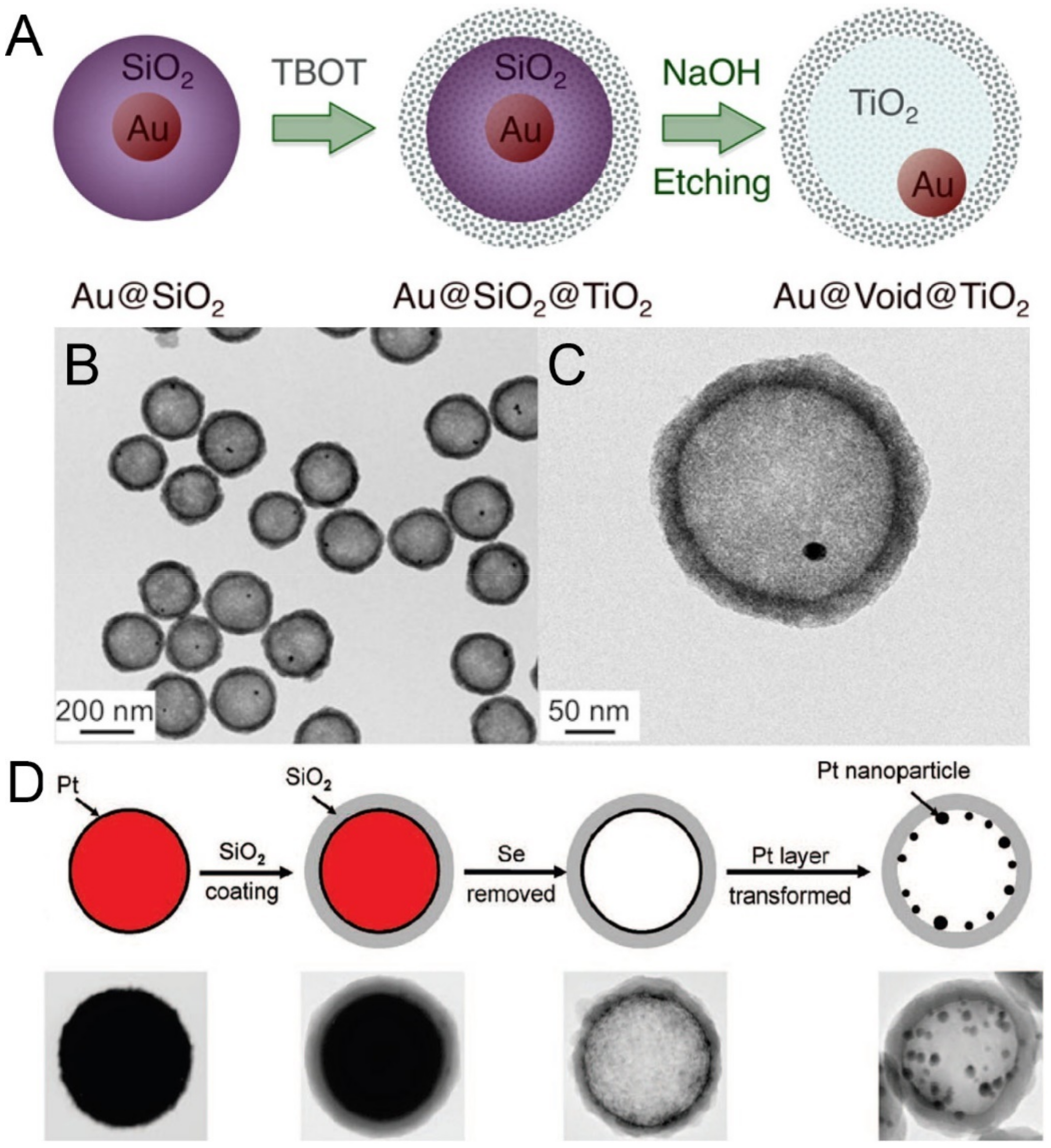
Templating method is the most common approach for building up yolk–shell nanostructures because it is conceptually straightforward in a way that templates can be removed leaving the cavity inside the shell. Templating synthesis is classified into hard-templating and soft-templating based on the kind of template materials, i.e., rigid or soft. Generally, templating approaches follow the steps below: formation of the core, template coating, coating of the outer layer, and removal of the sacrificial template. In some cases, the surface modification is necessary for the coating of the outer layer to confer suitable surface properties. The removal of the template can be done through chemical etching, solvent dissolution, and calcination to obtain the cavity inside the hollow shell. Figure 1A shows the synthetic scheme of yolk–shell nanostructured Au@TiO2 morphology for the cryogenic oxidation reaction catalyst of carbon monoxide [31]. Gold nanoparticles acting as the yolk were first coated with silica to form Au@SiO2 core–shell nanostructure through a sol–gel process. Then, an outer titania shell was deposited on the surface of silica using tetrabutyl titanate (TBOT) to generate Au@SiO2@TiO2 double-shell nanostructure. Finally, the silica was etched away by using an alkaline solution to create the void with the Au@TiO2 yolk–shell nanostructure. The resultant image of Au@TiO2 yolk–shell nanostructures is displayed in the TEM images of Figure 1B,C. The use of Au nanoparticles in catalyst has one limitation, which they are easy to sinter due to the size effect. This leads to the severe degradation of catalytic activity. Thus, the authors adopted the yolk–shell architecture as an appropriate nanoreactor for the catalytic reaction since the titania shell can isolate the gold nanoparticles from clustering and guarantee the transfer of gases in and out of the inner space for sufficient access to gold surfaces. Typical materials for templating are silica, carbon, metal, metal oxides, and oligomers [32,33]. Silica is one of the most frequently used hard templates for the fabrication of yolk–shell nanostructures due to its easy removal with alkali or hydrogen fluoride treatment. For example, Shi and co-workers reported that Au@mSiO2 and ellipsoidal Fe2O3@mSiO2 yolk–shell nanostructures by using sodium carbonate and ammonia solution as the etching agent [34]. Carbon has also been used as a hard template due to its easy removal through calcination. Spindle Fe2O3@mSiO2 yolk–shell nanostructures were reported by using carbon as the sacrificial template [23]. In general, the firstly-coated shell act as a sacrificial template to generate voids inside the hollow shells after the removal process. However, the innermost core material can also behave as the removal template for the formation of desired materials inside hollow shells. Figure 1D exhibits the schematic procedure of fabricating platinum nanoparticle-decorated hollow silica shell [35]. The platinum layer was coated on the surface of amorphous selenium colloids through chemical reduction in alcohol. Then, the Stöber process produces the silica coating on the surface of Pt shell to finally form Se@Pt@SiO2 double-shelled structures. The innermost core was removed by dissolving in appropriate solvent like alcohol and hydrazine. During the removal process, the Pt layer go through transformation into Pt nanoparticles depending on the material flux. While the slow dissolution of Se core tends to preserve the thin Pt layer, the high flux of the core induces the rearrangement of the Pt clusters into nanoparticles ranging from a few to tens of nanometers by adjusting the temperature and the solubility of the Se core in solvents.

2.2. Self-Templating Methods

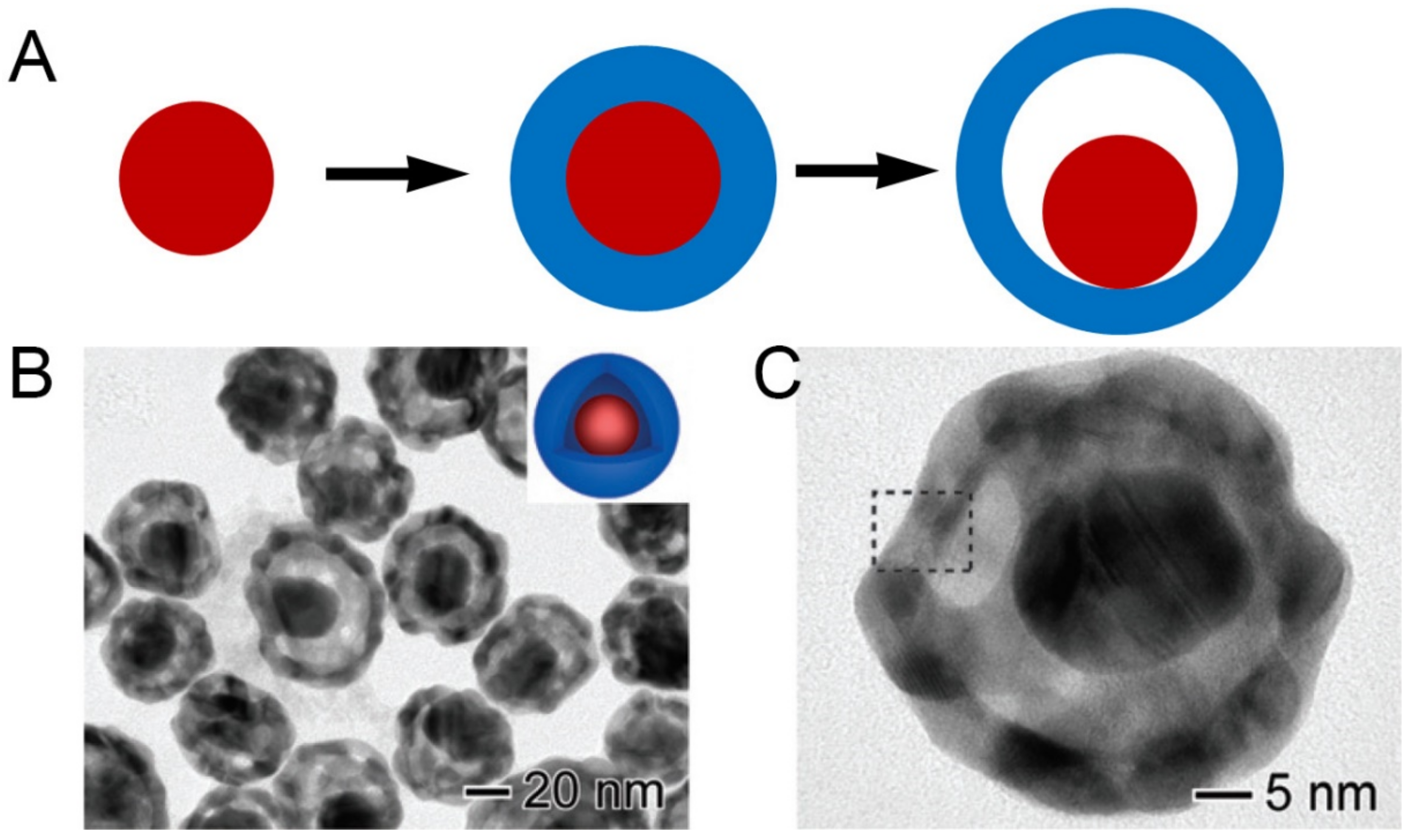
Unlike the conventional templating methods, direct syntheses of yolk–shell nanostructures have also been developed by self-templating approaches. The self-templating methods can contain the following categories: galvanic replacement, Kirkendall effect, Ostwald ripening, partial removal of the core, core injection, core contraction, and surface-protected etching. The galvanic replacement reaction happens at the interface of metals with the different electrical potential, in which one metal serves as a reducing agent and the other metal serves as an oxidizing agent, respectively. As a result, the metal with low reduction potential tends to oxidize by reducing the other metal ion into a reduced form. Generally, the core metal is coated with other metal which has higher reduction potential. Upon addition of the metal ions, the core metal tends to dissolve in the solution while the metal ions are reduced and plated on the surface of the core metal. Xia and co-workers reported the synthesis of Au/Ag@Au/Ag yolk–shell nanostructures based on the reduction potential difference between Au and Ag [36]. Figure 2 shows the illustration of the process for fabricating Au@Au/Ag yolk–shell nanostructure starting from Au@Ag core–shell through the galvanic replacement reaction [37]. During the reaction, the Ag shell is transformed into Au/Ag alloy by creating the hollow void between the core and the shell. The Kirkendall effect is also an efficient way to prepare yolk–shell nanostructures since the motion of the interface between two materials occurs due to different diffusion rates of atoms or ions. Alivisatos and co-workers reported that Au@iron oxide yolk–shell nanoparticles can be synthesized through the Kirkendall effect [38]. This process starts with the deposition of an iron shell on an Au core, followed by the oxidation of the iron shell into a hollow iron oxide shell as well as void formation inside. Ostwald ripening is also a well-known reaction that involves the dissolution of small crystals and the redeposition of the dissolved species on the surfaces of larger crystals. Recently, Caruso and co-workers demonstrated that titania@ammonium titanate yolk–shell nanostructures can be synthesized by the self-templating approach based on the Ostwald ripening mechanism [39]. A little more straightforward self-templating method is the partial removal of the core from core–shell structures. Core–shell structures with a core material being able to etched or dissolved can create void space inside the shell of the core–shell morphology. For example, Paik and co-workers reported the synthesis of Fe3O4@C yolk–shell nanocubes through the partial removal approach [40]. Fe2O3 nanocubes were coated with a PDA layer to form Fe2O3@PDA core–shell nanocubes, followed by annealing at 500 °C to transform into Fe2O3@C core–shell structures. Then, the Fe2O3 core was partially etched to create a cavity inside by using hydrochloric acid. Yi Cui and co-workers have demonstrated the synthesis of sulphur@TiO2 yolk–shell nanostructures through a partial dissolution of sulfur core in toluene [41]. The sulphur particles were coated with TiO2 through hydrolysis of titanium diisopropoxide bis(acetylacetonate) in solution to form sulphur@TiO2 core–shell structures. The following partial dissolution of sulfur in toluene creates an empty space between the sulfur core and the TiO2 shell, resulting in the yolk–shell shape. The internal void space can accommodate the volume expansion of sulphur by preserving the sulfur core from cracking and fracture inside the shell.
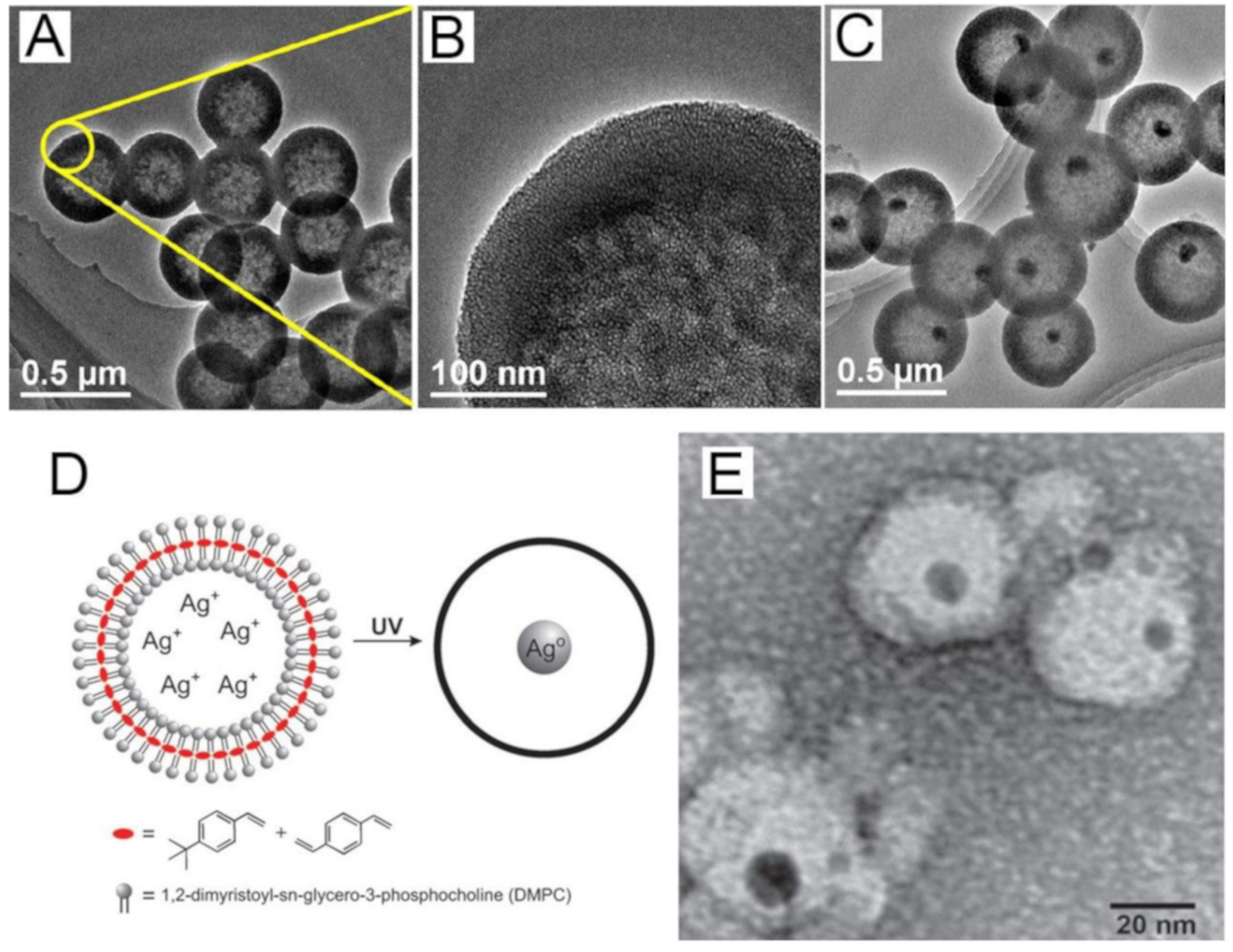
Yolk-shell morphology can also be synthesized through injecting the core material in a hollow shell from outside of the shell via transport along the pores. In this approach, the hollow shell act as the nanoreactors to confine and control the synthesis of the core, leading to the core–shell morphology with cavity [42]. Chen and co-workers have demonstrated the upconverting luminescent yolk–shell nanostructures by incorporating lanthanide-doped upconversion nanoparticles into hollow mesoporous silica [43]. Firstly, hollow mesoporous silica shell was prepared by a selective etching approach with an aid of a cationic surfactant. Then, the lanthanide-doped upconversion nanoparticles were synthesized within the hollow silica by loading precursor and calcination process to generate the core material inside. Lianjun Wang and co-workers have also demonstrated the yolk–shell nanostructure through an impregnation into a pre-formed hollow mesoporous silica nanosphere (Figure 3A,B) [44]. Fe@SiO2 yolk–shell nanospheres were synthesized by a sequential two-solvents impregnation-reduction method. Figure 3C shows the TEM image of the Fe@SiO2 yolk–shell nanosphere after the impregnation-reduction reaction. Lipid vesicles are also great nanoreactors for the synthesis of yolk–shell nanostructures through loading the core precursor in a hollow shell. Pinkhassik and co-workers reported the yolk–shell nanostructured Ag@polymer by using liposomes as the nanoreactors (Figure 3D,E) [45]. Liposomes with monomers and a photoinitiator in the bilayer and silver ions in the aqueous core were prepared by hydrating a mixture of lipids and monomers with a silver nitrate solution. The polymerization begins at the application of UV light and Ag nanoparticles starts to form with the aid of a photoinitiator. Finally, Ag@polymer yolk–shell nanostructure can be obtained. Likewise, Au@polymer yolk–shell nanostructures were also reported by loading reductant in a hollow nanocapsules [46]. Core contraction has also been studied as another promising strategy for synthesizing yolk–shell nanostructures. For example, the SnO2 yolk–shell particles were synthesized by spray pyrolysis at high temperature. The carbonization of sucrose within the precursor droplets changed into C–SnO2, followed by coating of SnO2 layer to form C–SnO2@SnO2 core–shell structures. Then, the combustion process induced the contraction of the C–SnO2 core to create void in the SnO2 shell. Other than the above methods, there have been other approaches to synthesize yolk–shell nanostructures such as surface-protected etching, fluid leakage, and hot-water-induced dissolution and reassembly [47,48,49].

3. Yolk–Shell Nanostructured Anodes

For the next-generation Li rechargeable batteries, the most ideal anode material for lithium rechargeable batteries is lithium meal in terms of the lowest anode potential (−3.04 V vs. SHE), high specific capacity (3860 mAh/g), lightweight (0.53 g/cm3), and no demand for Cu current collector [50]. The uncontrolled dendrite formation in Li metal anodes has become a hurdle against the practical employment [51]. The sharp Li dendrite can grow through the separator during the cycle, thus leading to an internal short circuit. Recent research to tackle this problem relies on solid electrolyte interphase stabilization/modification by adding additives or conducting scaffold to form stable SEI [52,53]. The safety issue is still not fully resolved for mass production in industries. As an alternative, lithium alloy-based materials have been investigated due to their higher theoretical capacities (4200 mAh/g for Si, 1,623 mAh/g for Ge, 994 mAh/g for Sn, and 2,235 mAh/g for Al) and low operating potentials (~0.5 V vs. Li/Li+ for Si) than graphite leading to greater energy and power densities [54]. However, alloy-based anodes experience catastrophic capacity fading because of the large volume change upon electrochemical cycling (e.g., ΔVSi = ~400% for full lithiation), which, in turn, may cause electrode pulverization and loss of contact with the current collector.
Despite the second highest abundance of silicon in nature and, thus, viable mass production, graphite anodes still dominate the marketplace due to major challenges preventing its widespread use. First of all, alloy anodes, including Si, undergo significant volume change, which leads to pulverization of the initial particle morphology and loss of electrical contact. Secondly, the low electrochemical potential of alloy-type anodes provokes thick SEI film due to the reductive decomposition of the organic electrolyte [55]. In addition, the SEI rupture from volume change and particle fracture during cycling and an electrolyte is continually consumed by exposing the electrode surface to the electrolyte. This excessive growth of SEI lows Coulombic efficiency by enhancing resistance to ionic and electronic transport. The stabilization of the SEI layer was obtained by surface coating with metal oxide and carbon [56,57,58]. However, those surface coatings cannot withstand the large volume changes of Si during discharge/charge cycles. Keeping the advantage of the surface coating, a new approach has recently been tried to give spatial room for active material to maintain its initial morphology despite the volume change by creating yolk–shell nanostructures [17,18,19]. Conversion-based anode materials also experience the large volume change during Li or Na insertion/extraction process leading to fast capacity fading. Transition metal oxides and sulfides have been prepared as yolk–shell nanostructures to provide stable SEI formation and increased electronic conductivity, especially when they are covered with carbonaceous materials. In this section, we will discuss the recent development of metals, metal oxides, and metal sulfides based on yolk–shell nanostructures for Li or Na rechargeable batteries. Table 1 shows various lithium/sodium rechargeable anode materials based on yolk–shell nanostructures.

3.1. Alloy-Type Materials

Alloying/de-alloying anode materials in LiBs and NIBs are attractive for their very high capacities. However, the large volume change upon electrochemical cycling is detrimental to commercializing them, so that several strategies have been developed: designing nanostructures and fabrication of composites with lithium material [110]. To alleviate the fast capacity fading due to electrode pulverization, capping materials, such as conductive carbon or porous metal oxides, can be exploited as a buffer layer to endure the large volume exchange during cycling. Core–shell and yolk–shell nanostructures are the examples in a way to provide the robust wall and surround the active electrode part. In terms of guaranteeing spacious room for nanostructured anode materials to keep their morphologies, yolk–shell nanostructures are advantageous compared to core–shell, which is necessary for alloy-type anode materials due to their very large volume change.

3.1.1. Silicon

Nanostructured Si anodes such as nanoparticles, nanowires, and nanotubes can relieve the huge morphological change and shorten the diffusion path of lithium ions. Nevertheless, pure Si nanomaterials tend to aggregate during lithiation/delithiation, leading to aggravation of electronic transport [111]. Hybridization of the nanostructured Si with electrochemically inactive matrix is an alternative to pure Si nanostructures. The inactive materials can stabilize Si nanomaterials and prevent the aggregation by alleviating the mechanical stress from huge volume change [112]. Unlike core–shell structured anodes, novel yolk–shell nanostructures have, recently, been on the focus of battery anode materials because the active core (yolk) can expand upon lithiation without breaking the shell and stabilize the SEI layer [18]. Especially, encapsulating Si nanoparticles with carbon has been the main idea of fabricating yolk–shell nanostructured Si anode due to its elastic nature and electronic conductivity. Many preparation methods include chemical etching (acid or base) the unnecessary silica or calcium carbonate layer after carbonization to create a void in the yolk–shell nanostructure [17,18,19,60,61,62,63,65].
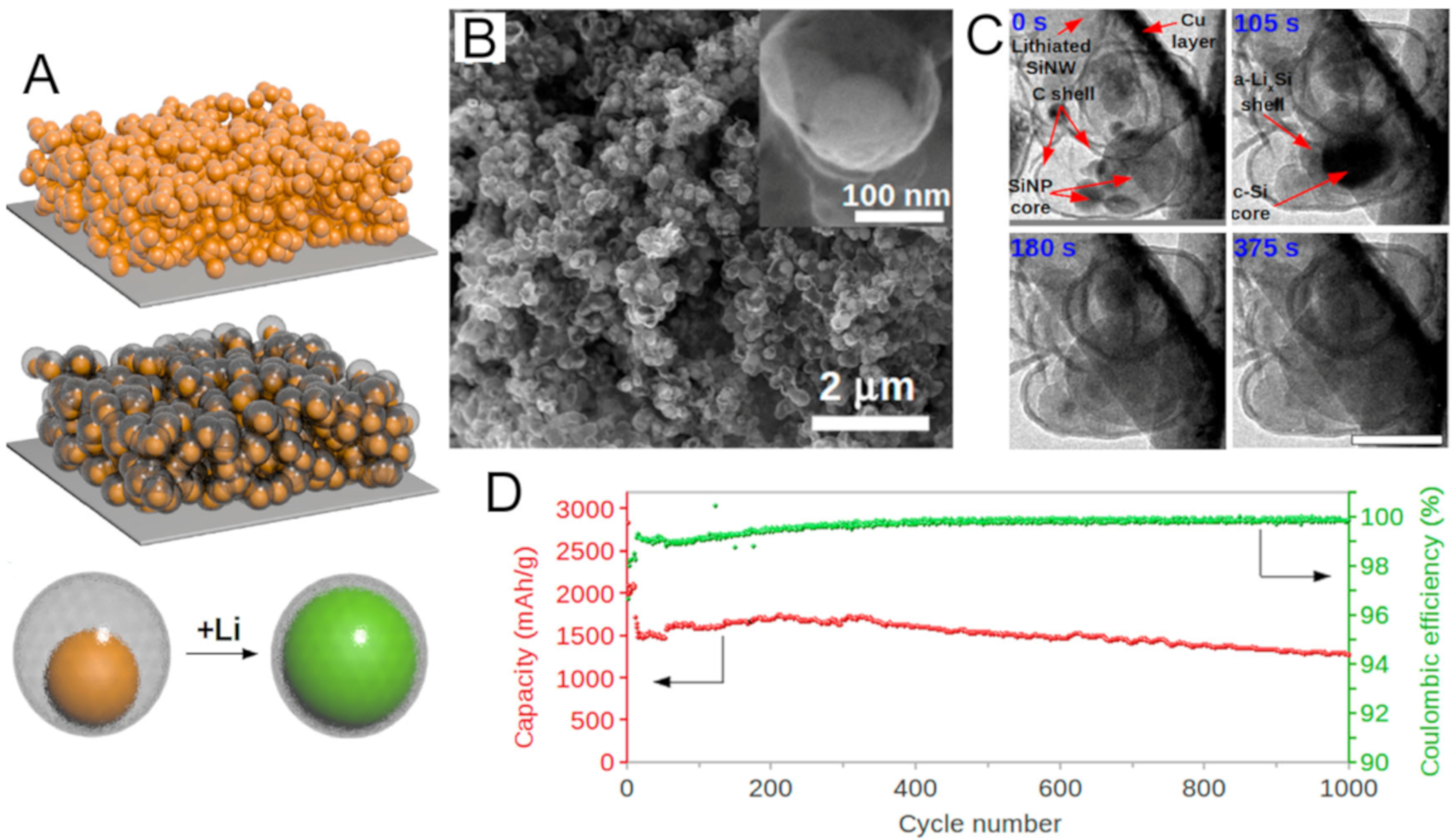
Cui and co-workers have, successfully, designed a Si@C yolk–shell nanostructure and demonstrated prolonged cycle life by characterizing the in-situ Si nanoparticle expansion during electrochemical lithiation [18]. A successful design for Si anode requires the following prerequisite: nanostructuring of silicon, stable SEI, well-controlled pore, and up-scaled fabrication. Figure 4A shows a comparative scheme between a conventional slurry Si nanoparticle electrode and Si@C yolk–shell electrode. The expansion of Si nanoparticles disrupts the microstructure of the electrode during lithiation in the case of the conventional slurry electrode. The void in the yolk–shell nanostructure allows Si to expand without rupturing the carbon coating layer, which enables a stable and thin SEI layer formation on the outer surface of the carbon. Furthermore, the volume change of the Si does not break the outer shell. The Si@C yolk–shell nanostructure was fabricated by coating, conformally, Si with SiO2 sacrificial layer and then polydopamine, followed by carbonization with nitrogen doping and selective removal of SiO2 layer in acidic solution (Figure 4B). This completely sealed structure was monitored with in-situ TEM to demonstrate that the Si@C yolk–shell provides excellent electrochemical cycling performance to alleviate the severe volume change of Si during lithiation/delithiation (Figure 4C). Pristine Si nanoparticles (0 s) are visible within the outer C shell. The volume expansion of Si nanoparticles is seen in 105 s to produce the partially lithiated LixSi shell/crystalline Si core in the carbon shell. Full lithiation increases the size of Si particles up to ~300 nm. Furthermore, the thickness of carbon shell increases from 5 to ~20 nm after lithiation implying that the carbon coating is also lithiated and creates a thin layer of ionic liquid electrolyte at the surface. Figure 4D shows the reversible capacity of Si@C yolk–shell electrode reached 2833 mAh/g for the initial cycle at C/10 and stabilized at ~1500 mAh/g at 1 C. No capacity retention was observed in the first 300 cycles and 74% of the capacity was achieved after 1000 cycles. In contrast, the bare Si nanoparticle and Si@C core–shell electrodes showed very fast capacity fading in the first 10 cycles. The stable SEI formation of the Si@C yolk–shell electrode was evident in the Coulombic efficiency profile.
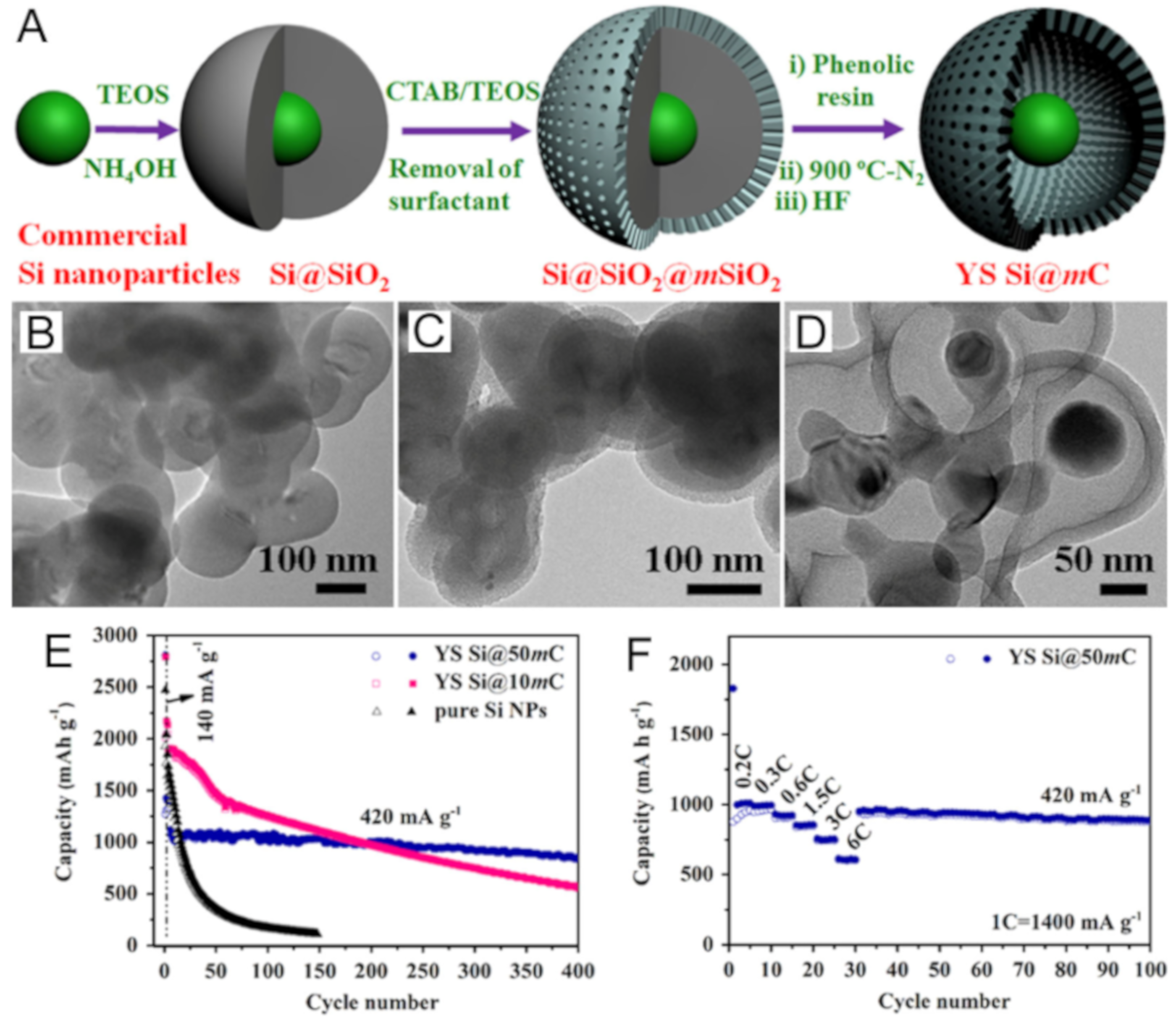
Open-ended mesoporous carbon shell was devised to facilitate the fast diffusion of Li+ ions and provide the full immersion of Si core materials in the electrolyte for higher rate capability [63]. Si@mC (mesoporous carbon) yolk–shell nanostructures are developed by Zhang and co-workers by using mesoporous SiO2 as a template, which is etched away later, to form mesoporous carbon shell containing Si nanoparticle in the core (Figure 5). For a comparative study, they prepared two types of Si@mC according to the void space inside the carbon shell (10 and 50 nm). The electrochemical cycling properties of Si@mC yolk–shell electrodes outperform the pure Si nanoparticle electrode (Figure 5E). Another notable observation is that enough space inside the carbon shell is important in terms of cycling performance and rate capacity retention. Small void is hard to afford the large volume expansion of Si, which can result in structural collapse of the carbon shell. Thus, the successful design of yolk–shell nanostructure takes into consideration the efficient volume expansion of Si core material. Other than the chemical etching method, spray pyrolysis is another approach to form yolk–shell Si nanostructures, i.e., Si@C, Si@NiO [59,64].

3.1.2. Tin and Tin Oxide

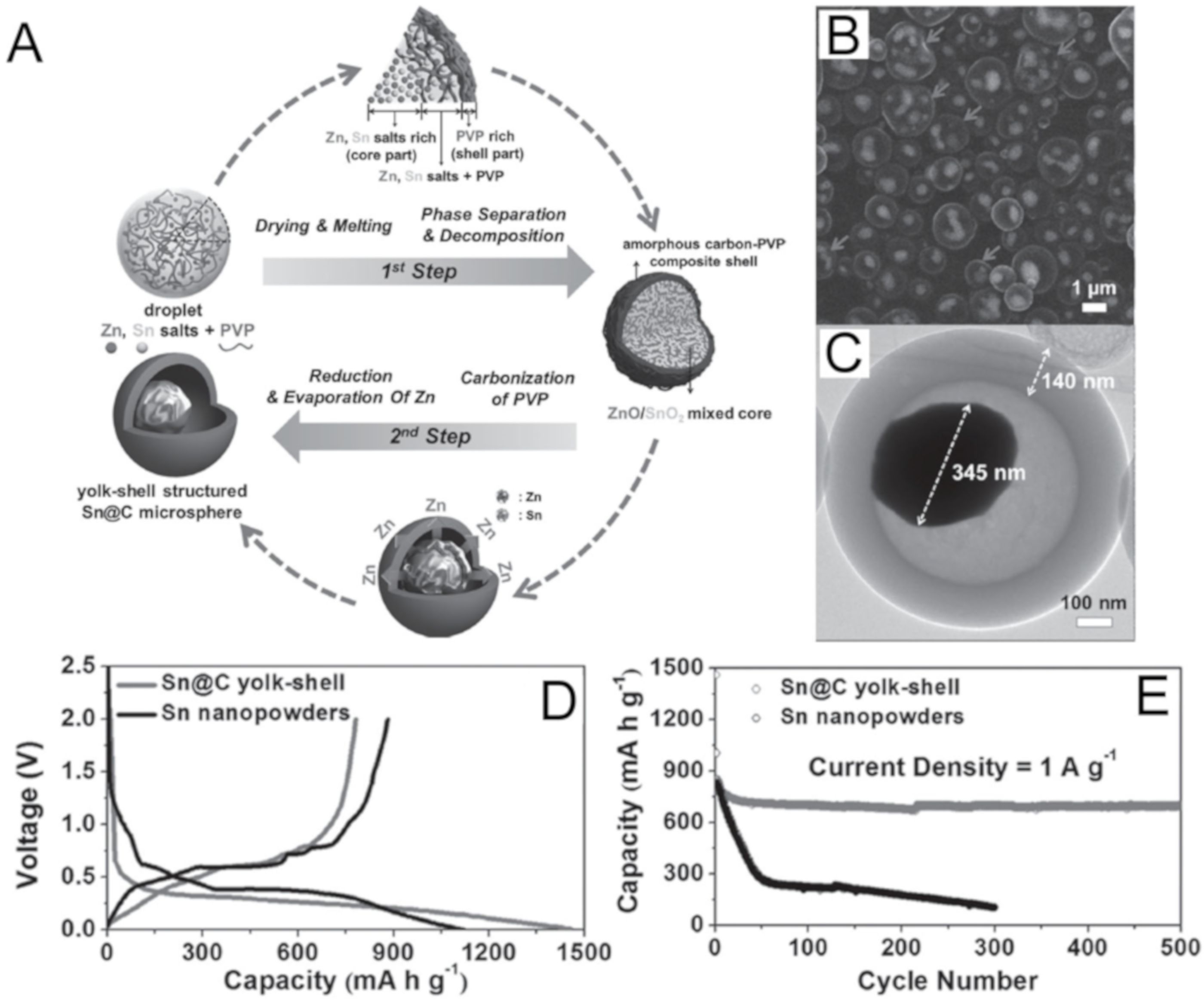
As an alloy-type anode alternative, tin is also a promising material due to its high specific capacity and low operating potential. Although tin cannot beat silicon in terms of gravimetric capacity (4200 vs. 991 mAh/g, based on the formation of Li4.4Sn, Sn + 4.4Li+ +4.4e ↔ Li4.4Sn), it has a comparable volumetric capacity of 2020 mAh/cm3 (2400 mAh/cm3 for Si) and better electrical resistivity than graphite [113]. Nevertheless, tin is prone to capacity deterioration during charging/discharging, like other alloy-type anode materials, due to huge volume change (~300%) leading to electrode pulverization, delamination from the current collector, and SEI formation. Designing pure tin anode as nanostructure has been suggested to alleviate the stress of tin from volume expansion [113]. Intrinsic volume change during lithiation/delithiation pushes the research towards using the buffer layer to keep tin nano-/micro-scale anode from pulverization by creating core-protected structure. Kang and co-workers have demonstrated that yolk–shell nanostructured Sn@C electrode showed better cycling stability than pure Sn powder [66]. Carbon-coated Sn microsphere was prepared by spray pyrolysis (Figure 6). Firstly, SnO2–ZnO@C microsphere (core–shell) was synthesized and, then, transformed to yolk–shell Sn@C microsphere by reducing SnO2 and vaporizing Zn (low vaporizing temp. of Zn, ~900 °C). H2/Ar mixture gas reduced SnO2 and ZnO and the undecomposed PVP created a carbonized shell at 1000 °C. Figure 6C shows the reduced Sn yolk covered with carbon shell. The yolk–shell Sn@C electrode showed initial discharge and charge capacities of 1458 and 781 mAh/g indicating an initial Coulombic efficiency of 54%. In comparison, the pure tin nanopowder electrode has 75% of initial Coulombic efficiency due to a large irreversible capacity from an amorphous carbon shell in yolk–shell electrode. However, the yolk–shell Sn@C electrode showed a better long-term cycling performance in Figure 6E. The capacity retention of Sn@C electrode is 83% from the second cycle to 500th cycle. The stable cycling is attributed to the void in yolk–shell nanostructure, in which Sn can maintain its morphology inside the carbon shell during lithiation/delithiation. The concept of Sn@C yolk–shell nanostructure was also demonstrated in the form of nanotube [67], integration with nanofiber [68,71], and core-sheath nanowire [69].
Tin oxide has the lowest operating voltages (0.3 and 0.5 V vs. Li/Li+, for discharge and charge) among other transition metal oxides. Tin oxide is also classified as alloy-type anode materials according to the following electrochemical processes: [114]
SnO2 + 4Li+ + 4e ↔ Sn + 2Li2O
Sn + xLi+ + xe ↔ LixSn (0 ≤ x ≤ 4.4)
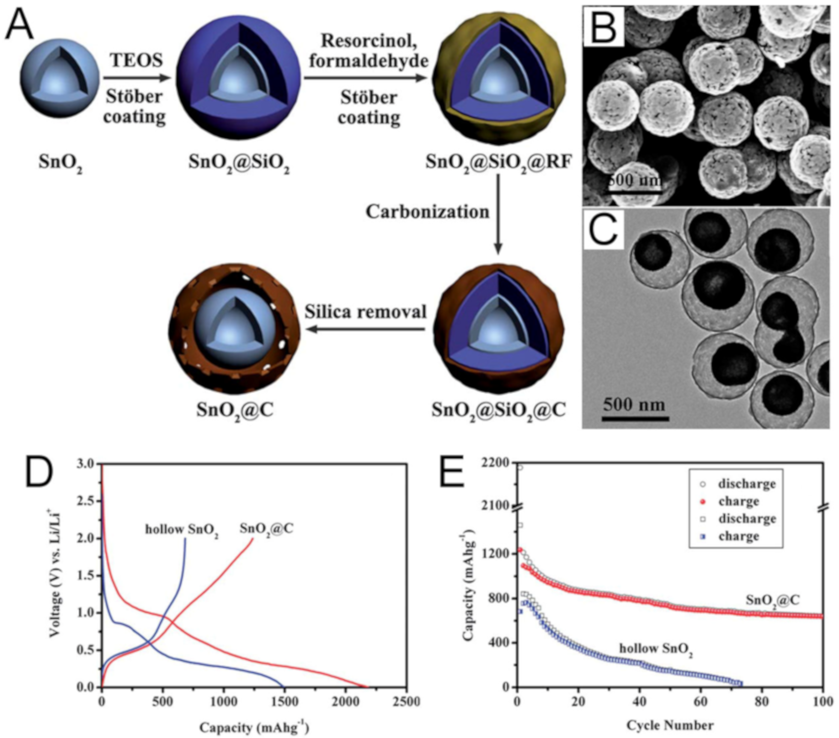
Thus, tin oxide is one of the alloy-type anode materials that has been investigated to design yolk–shell nanostructure for stable long-term cycling. Mostly, tin oxide nanoparticles were coated with a carbonaceous shell, followed by etching the template or buffer layer and carbonization at high temperatures. Well-controlled SnO2@C yolk–shell nanospheres were reported by Zhao and co-workers (Figure 7) [72]. Uniform SnO2@C nanospheres were synthesized by coating silica layer and resorcinol-formaldehyde (RF). The silica layer was etched and RF was carbonized to form hollow SnO2@C yolk–shell nanostructure (Figure 7A). Figure 7B,C shows the SEM and TEM images of hollow SnO2@C nanospheres after carbonization. The size of the void space and the thickness of the carbon shell can be controlled by controlling the precursors of silica and carbon. Due to the carbon shell, the first discharge/charge capacities of SnO2@C exhibit a larger value of 2190 and 1236 mAh/g than those of pure SnO2 electrode, respectively (Figure 7D). Despite the lower first Coulombic efficiency of SnO2@C (43%), the yolk–shell nanostructure shows the improved cycling performance with a high reversible capacity of ~950 mAh/g after 10 cycles and ~630 mAh/g after 100 cycles (Figure 7E). In contrast, the pure SnO2 electrode approaches to zero capacity after 70 cycles indicating that the carbon shell and void in yolk–shell SnO2@C facilitate the cycling stability.

3.1.3. Aluminum

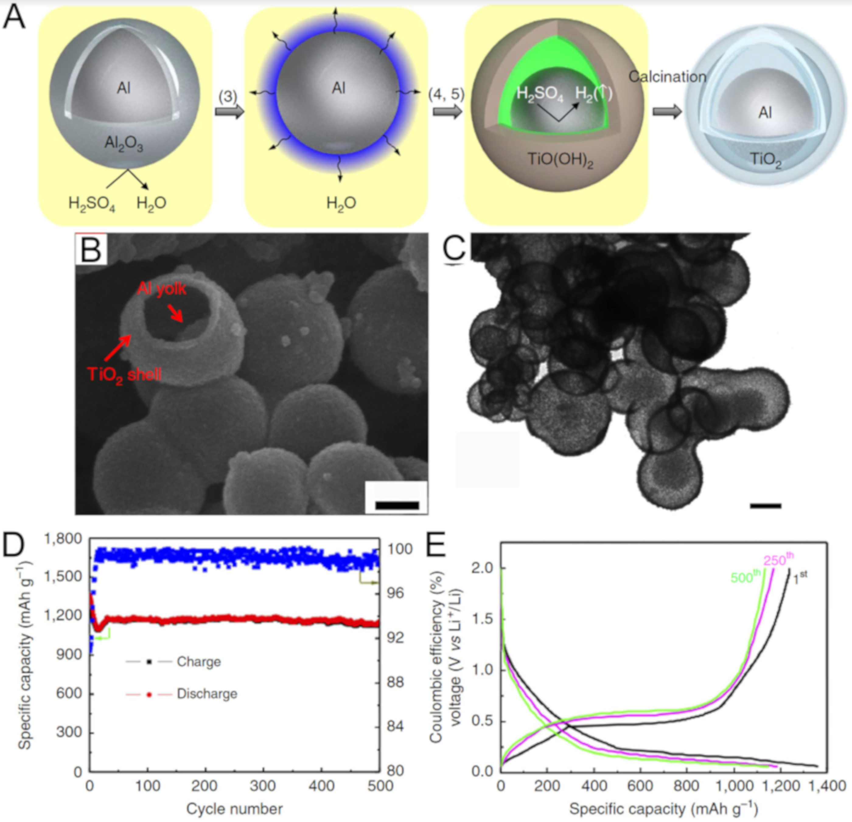
Aluminum is another attractive alloy-type anode material owing to cheap price ($2000/ton), high theoretical capacity (2235 mAh/g, based on 4Al + 9Li+ + 9e ↔ Li9Al4), and high electrical conductivity [115]. However, the practical performance is still suffering from relatively low capacity due to the electrode damage from the volume change (~100%) and pulverization. Even the hybrid structure of aluminum nanoparticles with carbon achieved only ~900 mAh/g [116]. Instead of carbon shell, inorganic and mesoporous TiO2 shell was employed as a constituent of yolk–shell Al@TiO2 anode material by Li and co-workers [77]. The yolk–shell Al@TiO2 nanospheres were synthesized through forming TiO(OH) and etching Al2O3 on the surface of aluminum particles to create a void inside the shell. TiO(OH) shell is converted to anatase TiO2 by calcination at 450 °C (Figure 8A). The resultant yolk–shell Al@TiO2 nanospheres have an aluminum core (~30 nm) and TiO2 shell (~3 nm) with a controllable void space (Figure 8B,C). The Al@TiO2 yolk–shell nanosphere electrode has a long lifecycle, which maintains ~1100 mAh/g after 500 cycles at 1 C rate with 93% of Coulombic efficiency (Figure 8D,E). Even at 10 C rate, the electrode achieved a capacity of 661 mAh/g after 500 cycles. The high rate performance is attributed to the good electrical conductivity of aluminum. Compared to silicon-carbon yolk–shell electrodes, Al@TiO2 has lower capacity at a low rate (1 C), but exhibits higher rate performance after a long cycle. The Al@TiO2 has a few times larger specific capacity than LTO and graphite.

3.2. Conversion Materials

Conversion-based anode materials follow the electrochemical reaction mechanism to form transition metal compounds such as oxides, phosphides, sulfides, selenides and nitrides with lithium or sodium. These materials involve the reduction (oxidation) of the transition metal along with the composition (decomposition) of lithium or sodium compounds (LixXy, NaxXy; X = O, P, S, Se, N). A high number of electrons in the conversion reaction of these materials can induce high reversible capacities. Nevertheless, metal oxides have some issues such as very low electrical conductivity, unstable SEI formation, and poor capacity retention due to phase segregation, volume change, and ionic/electronic transport [9]. Thus, as a buffer layer or conducting layer, yolk–shell nanostructure has been employed to improve electrochemical properties of conversion-type anode materials. Synthetic approaches can be classified into four mechanisms based on the step of void formation: spray pyrolysis, Ostwald ripening, etching, and thermal treatment.
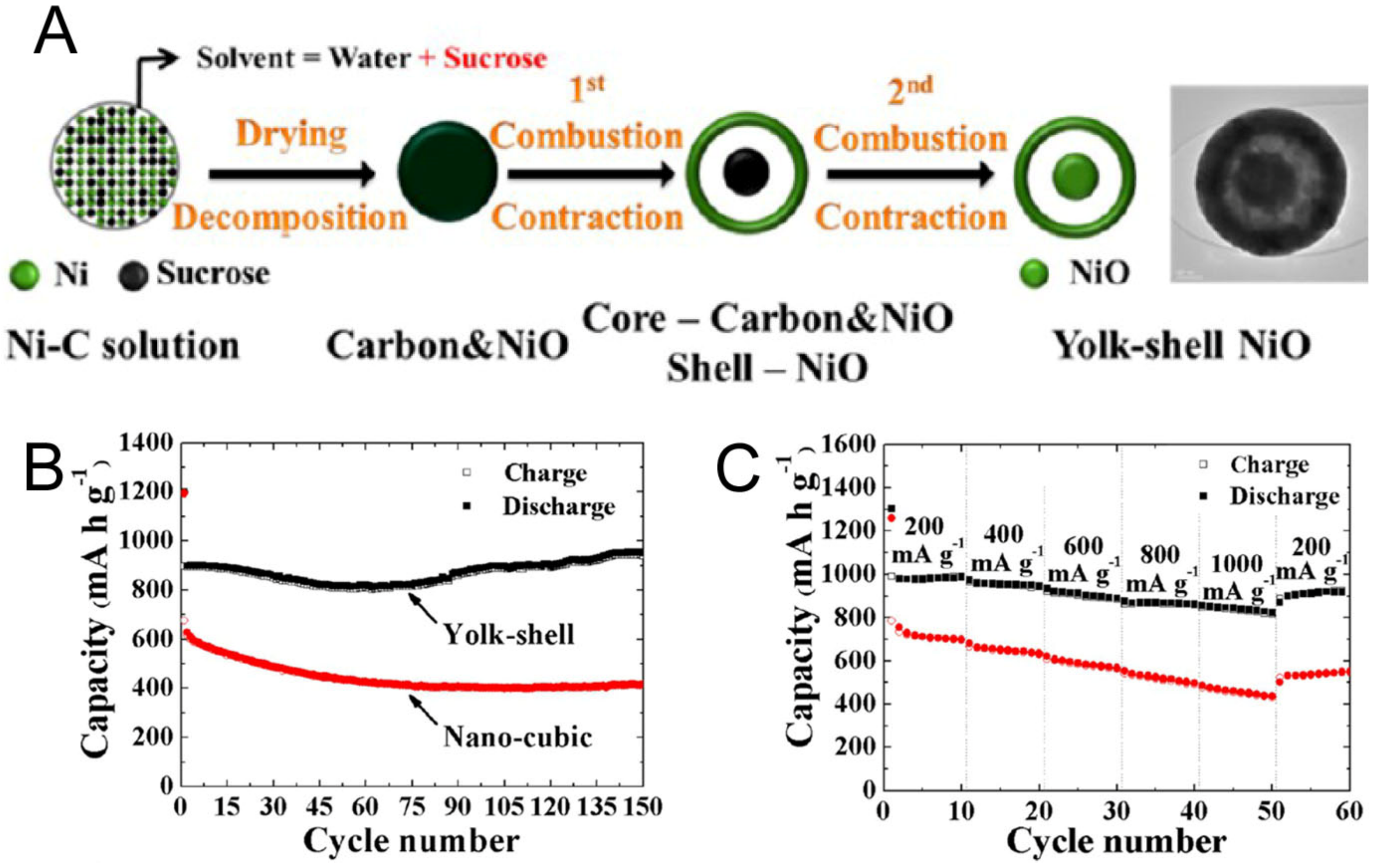
Spray pyrolysis is a continuous and rapid one-pot process for fabricating micro-/nanopowder. In addition, neither template material nor etching step is necessary compared to the templating method. Various transition metal oxides can be synthesized by spray pyrolysis with high crystallinity for a few seconds. The morphologies of the yolk–shell particles prepared by spray pyrolysis were affected by the types of spray solution and temperature. The formation of carbon-metal oxide particles was formed as an intermediate product, followed by decomposition of precursors and combustion of carbon to create yolk–shell nanostructure. Thus, most yolk–shell particles synthesized by spray pyrolysis have the same composition of shells with core materials. Figure 9 shows the formation of yolk–shell NiO@NiO nanoparticle, demonstrated by Kang and co-workers [91]. A dense carbon/NiO intermediate particle was formed from Ni-Sucrose droplet by the decomposition of nickel nitrate and the carbonization of sucrose. Further combustion of the intermediate particle produced core–shell carbon/NiO@NiO composite and, finally, yolk–shell NiO@NiO particles after carbon combustion. For a comparative study, the electrochemical measurements were performed with both the yolk–shell NiO@NiO and single-crystalline cubic NiO particles. Figure 9B shows the cycling performances of the two electrodes at 1 C. Whereas the cubic NiO electrode showed no increase in discharge capacities after 150 cycles, the yolk–shell electrode experienced capacity increase after 60 cycles. This is attributed to the formation of a gel-like film of the transition metal oxides due to small grain and size [117]. The rate performance of the yolk–shell NiO@NiO is slightly better than the pure cubic particle (Figure 9C). The simple and self-templating spray pyrolysis have been applied to fabricate various metal oxides yolk–shell nanostructure; Co3O4 [78], CoMn2O4 [79], Fe2O3 [83], NiMoO4 [92], ZnCo2O4 [97], ZnFe2O4 [98], ZnO/Mn3O4 [99], MoSe2 [102] and mixed metal oxides [118]. Furthermore, chemical transformation can produce transition metal sulfide yolk–shell nanostructure by an anion exchange. The prepared yolk–shell SnO2 particles can be converted into yolk–shell SnS particles through sulfidation [103].
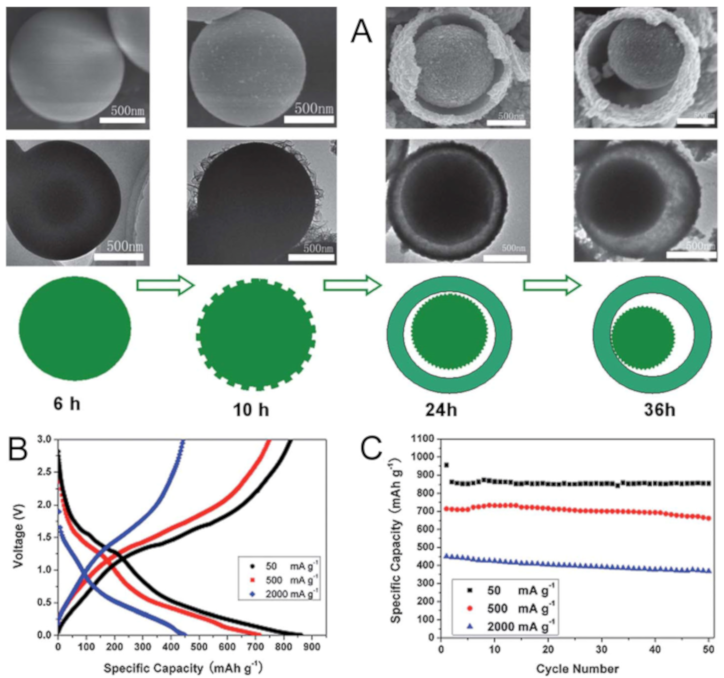
Ostwald ripening is another approach to form yolk-shell nanostructure without template material. Generally, a solid material starts to dissolve or evacuate and a shell is formed on the surface of the solid core at the expense of dissolving the core material due to the high surface energy. Figure 10A shows the sequential steps of the formation of the yolk–shell MoO2 microsphere through Ostwald ripening. From the SEM images, the smooth microsphere starts to form small nanoparticles on the surface and the growth of the shell, followed by creating void inside. The resultant yolk–shell MoO2 is crystalline with monoclinic MoO2 phase. The rate performance and cycling stability of the yolk–shell MoO2 electrode is reasonable, which has 714 and 450 mAh/g at 0.5 A/g and 2 A/g, respectively (Figure 10B,C). This enhanced electrochemical performance of the MoO2 microspheres can be originated from the better kinetics of the yolk–shell nature, which facilitates the electrolyte to transport Li ions during intercalation/deintercalation. Other anode materials structured as yolk–shell are also investigated by Ostwald ripening; TiO2 [106], V2O3 [94], ZnO [95], ZnO@ZnO/NiO [96], CoS2 [100].
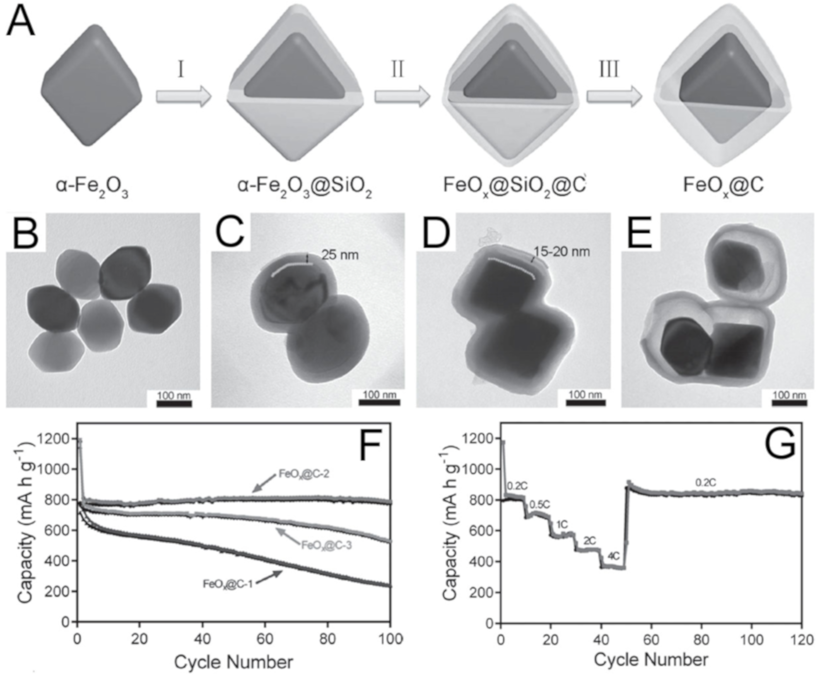
Templating approach towards yolk–shell nanostructure design is beneficial in a way that heterogeneous shell materials can be coated around the core, followed by the elimination of unwanted materials. One of the most historic methods to use template material for yolk-shell nanostructure is coating the first layer and then etching that layer after coating the second layer. Most Si@C yolk–shell nanostructures were achieved by the etching method. Likewise, metal oxides can also be produced as a yolk–shell particle through the etching method. An iron oxid@carbon yolk–shell nanostructure was designed through etching by Yu and co-workers [82]. α-Fe2O3 nanocrystals were coated with a conformal silica layer by controlled hydrolysis and condensation of TEOS to form α-Fe2O3@SiO2 (Figure 11A). Poly-dopamine was coated on the surface, followed by carbonization to obtain FeOx@SiO2@C nanoparticles. Basic solution was used to remove the sacrificial silica layer. The resultant FeOx@C yolk–shell nanoparticles have a controllable void size depending on the thickness of the silica layer (Figure 11B–E). The optimal void size of FeOx@C yolk–shell anode material was investigated by performing electrochemical tests. Figure 11F shows the cycling performance of the yolk–shell electrode indicating that FeOx@C-2 (silica layer thickness: 15~20 nm) achieved the highest and stable long-term capacity value, compared to the thinner (~9 nm) and thicker layer (~45 nm). FeOx@C-2 electrode delivers a high capacity of 820 mAh/g at 0.2 C and ~380 mAh/g at 4 C, which is comparable to the theoretical capacity of graphite (Figure 11G). FeOx@C-2 outperforms the other FeOx@C electrodes since the small void space was found to rupture the carbon shell after cycling, which is indicative of insufficient space for volume expansion. However, in the case of the thicker FeOx@C nanoparticles, volumetric capacity becomes lower. Templating methods through etching has produced other metal or metal oxide yolk–shell nanostructures; Fe2O3@C [80], Fe3O4@C [81], MnO2@C [86], Ni@graphene [89].
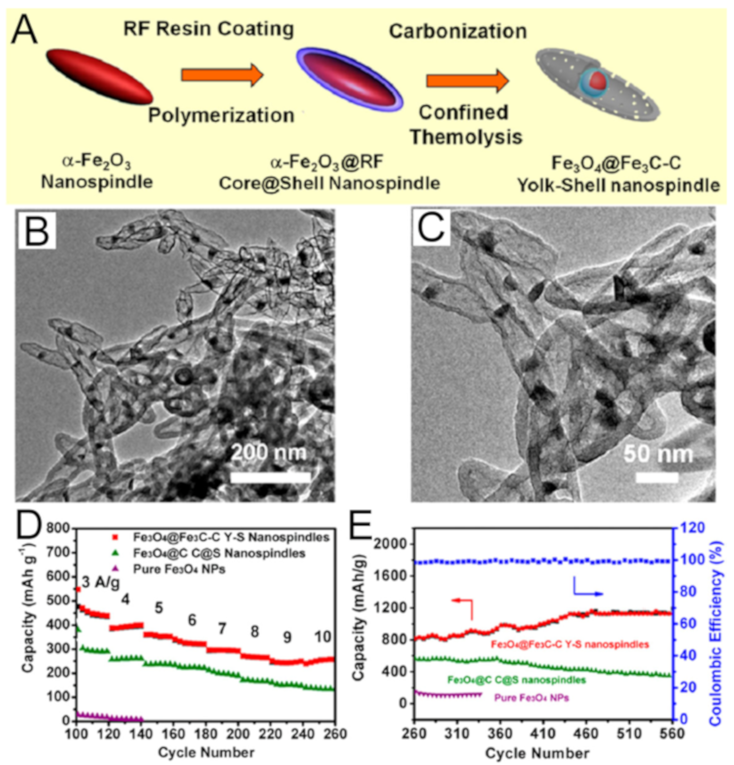
Yolk–shell nanostructures containing carbon shell can be obtained by thermal treatment to carbonize a carbonaceous shell material, followed by contraction of core materials to create a void. Fe3O4/Fe3C@C yolk–shell nanospindles were synthesized by Guo and co-workers. Firstly, uniform α-Fe2O3 nanospindle were prepared by hydrothermal reaction and coated with a conformal RF resin layer to form α-Fe2O3@RF core–shell structure (Figure 12A). Thermal treatment at 550 °C produced Fe3O4/Fe3C@C yolk–shell nanostructure by escaping the core from the carbon shell (Figure 12B,C). Interestingly, only Fe3O4@C core–shell nanospindles were obtained when RF was replaced by another carbonaceous material (glucose). The electrochemical performance of Fe3O4/Fe3C@C yolk–shell nanospindles were compared with pure Fe3O4 nanoparticle and Fe3O4@C core–shell nanospindle in Figure 12D,E. The Fe3O4/Fe3C@C yolk–shell nanospindles outperforms the other two electrodes in terms of rate capability and long-term cycling stability. The increasing capacity of Fe3O4/Fe3C@C yolk–shell nanospindles in Figure 12D can be found in metal oxide electrodes [119,120]. Metal oxide yolk–shell nanostructures synthesized by thermal treatment include Cr2O3@TiO2 [47], Fe3O4@TiO2 [84], FeOx@graphene [44], MnO2@C [85], NiO@C [88] and TiO2@C [108].

4. Conclusions and Outlook

In this review, the yolk–shell nanostructures are covered in terms of designing strategies and applications in lithium and sodium battery anode materials. Compared to the conventional core–shell structure, the hollow shell containing the movable core possesses unique morphological features bringing low density, large surface area, and great loading capacity. Typically, the building-up of yolk–shell nanostructures can be classified into templating and self-templating approaches according to the use of the sacrificial layer and the necessity of the removal process. Templating methods usually exploit rigid or soft materials as sacrificial materials such as SiO2, carbon, metal, metal oxides, oligomers, and vesicles. While the templating approaches are straightforward due to the role of an additional layer, the self-templating methods cover a wide range of synthetic strategies such as galvanic replacement, Kirkendall effect, Ostwald ripening, partial removal of core, core injection, core contraction, surface-protected etching, and so on. The yolk–shell nanostructured materials have the potential for battery anode due to their morphological features relieving volume expansion and facilitating rapid diffusion with electron transportation. These superior merits of yolk–shell nanostructured anodes were demonstrated from the many reports on the improvement of Li and Na storage performance with high specific capacity, rate capability, and stable long-term cyclability. Nevertheless, further study is needed to focus on developing advanced morphologies for more precise control over the shape and function. In addition, the environmentally-friendly etching or dissolution process should be explored because the usual dissolution solvents like hydrofluoric acid are very harmful. Since sodium ions are larger than lithium ions, it is also required to find suitable materials with appropriate morphologies for the reasonable volume expansion ratio and high specific capacity. Definitely, the yolk–shell nanostructures with tailorable inner space are promising for improving battery performance in the near future only if a commercially available process is set up.

Funding

This research was funded by Basic Science Research Program through the National Research Foundation of Korea (NRF) funded by the Ministry of Education (No. 2017R1D1A1B030274) and Korea Institute of Industrial Technology (No. EO20016).

Conflicts of Interest

The author declares no conflict of interest.

References

  1. Tang, Y.; Zhang, Y.; Li, W.; Ma, B.; Chen, X. Rational material design for ultrafast rechargeable lithium-ion batteries. Chem. Soc. Rev. 2015, 44, 5926–5940. [Google Scholar] [CrossRef] [PubMed]
  2. Goriparti, S.; Miele, E.; De Angelis, F.; Di Fabrizio, E.; Proietti Zaccaria, R.; Capiglia, C. Review on recent progress of nanostructured anode materials for Li-ion batteries. J. Power Sources 2014, 257, 421–443. [Google Scholar] [CrossRef] [Green Version]
  3. Bai, L.; Fang, F.; Zhao, Y.; Liu, Y.; Li, J.; Huang, G.; Sun, H. A sandwich structure of mesoporous anatase TiO2 sheets and reduced graphene oxide and its application as lithium-ion battery electrodes. RSC Adv. 2014, 4, 43039–43046. [Google Scholar] [CrossRef]
  4. Luo, W.; Shen, F.; Bommier, C.; Zhu, H.; Ji, X.; Hu, L. Na-Ion Battery Anodes: Materials and Electrochemistry. Acc. Chem. Res. 2016, 49, 231–240. [Google Scholar] [CrossRef]
  5. Chan, C.K.; Peng, H.; Liu, G.; McIlwrath, K.; Zhang, X.F.; Huggins, R.A.; Cui, Y. High-performance lithium battery anodes using silicon nanowires. Nat. Nanotechnol. 2008, 3, 31–35. [Google Scholar] [CrossRef]
  6. Oumellal, Y.; Delpuech, N.; Mazouzi, D.; Dupre, N.; Gaubicher, J.; Moreau, P.; Soudan, P.; Lestriez, B.; Guyomard, D. The failure mechanism of nano-sized Si-based negative electrodes for lithium ion batteries. J. Mater. Chem. 2011, 21, 6201–6208. [Google Scholar] [CrossRef]
  7. Dang, H.X.; Klavetter, K.C.; Meyerson, M.L.; Heller, A.; Mullins, C.B. Tin microparticles for a lithium ion battery anode with enhanced cycling stability and efficiency derived from Se-doping. J. Mater. Chem. A 2015, 3, 13500–13506. [Google Scholar] [CrossRef]
  8. Liu, Y.; Zhang, S.; Zhu, T. Germanium-Based Electrode Materials for Lithium-Ion Batteries. ChemElectroChem 2014, 1, 706–713. [Google Scholar] [CrossRef]
  9. Wu, H.B.; Chen, J.S.; Hng, H.H.; Wen Lou, X. Nanostructured metal oxide-based materials as advanced anodes for lithium-ion batteries. Nanoscale 2012, 4, 2526–2542. [Google Scholar] [CrossRef]
  10. Wang, X.; Chen, D.; Yang, Z.; Zhang, X.; Wang, C.; Chen, J.; Zhang, X.; Xue, M. Novel Metal Chalcogenide SnSSe as a High-Capacity Anode for Sodium-Ion Batteries. Adv. Mater. 2016, 28, 8645–8650. [Google Scholar] [CrossRef]
  11. Wang, X.; Kim, H.-M.; Xiao, Y.; Sun, Y.-K. Nanostructured metal phosphide-based materials for electrochemical energy storage. J. Mater. Chem. A 2016, 4, 14915–14931. [Google Scholar] [CrossRef]
  12. Balogun, M.-S.; Qiu, W.; Wang, W.; Fang, P.; Lu, X.; Tong, Y. Recent advances in metal nitrides as high-performance electrode materials for energy storage devices. J. Mater. Chem. A 2015, 3, 1364–1387. [Google Scholar] [CrossRef]
  13. Cho, J.S.; Lee, S.Y.; Kang, Y.C. First Introduction of NiSe2 to Anode Material for Sodium-Ion Batteries: A Hybrid of Graphene-Wrapped NiSe2/C Porous Nanofiber. Sci. Rep. 2016, 6, 23338. [Google Scholar] [CrossRef] [PubMed] [Green Version]
  14. Lai, C.-H.; Lu, M.-Y.; Chen, L.-J. Metal sulfide nanostructures: Synthesis, properties and applications in energy conversion and storage. J. Mater. Chem. 2012, 22, 19–30. [Google Scholar] [CrossRef]
  15. Zuo, X.; Zhu, J.; Müller-Buschbaum, P.; Cheng, Y.-J. Silicon based lithium-ion battery anodes: A chronicle perspective review. Nano Energy 2017, 31, 113–143. [Google Scholar] [CrossRef]
  16. Zhao, Y.; Wang, L.P.; Sougrati, M.T.; Feng, Z.; Leconte, Y.; Fisher, A.; Srinivasan, M.; Xu, Z. A Review on Design Strategies for Carbon Based Metal Oxides and Sulfides Nanocomposites for High Performance Li and Na Ion Battery Anodes. Adv. Energy Mater. 2017, 7, 1601424. [Google Scholar] [CrossRef]
  17. Xiao, X.; Zhou, W.; Kim, Y.; Ryu, I.; Gu, M.; Wang, C.; Liu, G.; Liu, Z.; Gao, H. Regulated Breathing Effect of Silicon Negative Electrode for Dramatically Enhanced Performance of Li-Ion Battery. Adv. Funct. Mater. 2015, 25, 1426–1433. [Google Scholar] [CrossRef]
  18. Liu, N.; Wu, H.; McDowell, M.T.; Yao, Y.; Wang, C.; Cui, Y. A Yolk-Shell Design for Stabilized and Scalable Li-Ion Battery Alloy Anodes. Nano Lett. 2012, 12, 3315–3321. [Google Scholar] [CrossRef] [Green Version]
  19. Zhang, L.; Rajagopalan, R.; Guo, H.; Hu, X.; Dou, S.; Liu, H. A Green and Facile Way to Prepare Granadilla-Like Silicon-Based Anode Materials for Li-Ion Batteries. Adv. Funct. Mater. 2016, 26, 440–446. [Google Scholar] [CrossRef] [Green Version]
  20. Khalifa, H.; El-Safty, S.A.; Reda, A.; Elmarakbi, A.; Metawa, H.; Shenashen, M.A. Multifaceted geometric 3D mesopolytope cathodes and its directional transport gates for superscalable LIB models. Appl. Mater. Today 2020, 19, 100590. [Google Scholar] [CrossRef]
  21. Chen, H.; Qi, B.; Moore, T.; Wang, F.; Colvin, D.C.; Sanjeewa, L.D.; Gore, J.C.; Hwu, S.-J.; Mefford, O.T.; Alexis, F.; et al. Multifunctional Yolk-in-Shell Nanoparticles for pH-triggered Drug Release and Imaging. Small 2014, 10, 3364–3370. [Google Scholar] [CrossRef] [PubMed]
  22. Li, X.; Zhou, X.; Guo, H.; Wang, C.; Liu, J.; Sun, P.; Liu, F.; Lu, G. Design of Au@ZnO Yolk–Shell Nanospheres with Enhanced Gas Sensing Properties. ACS Appl. Mater. Interfaces 2014, 6, 18661–18667. [Google Scholar] [CrossRef] [PubMed]
  23. Cui, Z.-M.; Chen, Z.; Cao, C.-Y.; Jiang, L.; Song, W.-G. A yolk–shell structured Fe2O3@mesoporous SiO2 nanoreactor for enhanced activity as a Fenton catalyst in total oxidation of dyes. Chem. Commun. 2013, 49, 2332–2334. [Google Scholar] [CrossRef] [PubMed]
  24. Park, J.H.; Kim, D.I.; Hong, S.G.; Seo, H.; Kim, J.; Moon, G.D.; Hyun, D.C. Poly(ε-caprolactone) (PCL) Hollow Nanoparticles with Surface Sealability and On-Demand Pore Generability for Easy Loading and NIR Light-Triggered Release of Drug. Pharmaceutics 2019, 11, 528. [Google Scholar] [CrossRef] [Green Version]
  25. Wu, S.; Dzubiella, J.; Kaiser, J.; Drechsler, M.; Guo, X.; Ballauff, M.; Lu, Y. Thermosensitive Au-PNIPA Yolk–Shell Nanoparticles with Tunable Selectivity for Catalysis. Angew. Chem. Int. Ed. 2012, 51, 2229–2233. [Google Scholar] [CrossRef]
  26. Yang, Y.; Liu, X.; Li, X.; Zhao, J.; Bai, S.; Liu, J.; Yang, Q. A Yolk–Shell Nanoreactor with a Basic Core and an Acidic Shell for Cascade Reactions. Angew. Chem. Int. Ed. 2012, 51, 9164–9168. [Google Scholar] [CrossRef]
  27. Yang, P.; Luo, X.; Wang, S.; Wang, F.; Tang, C.; Wang, C. Biodegradable yolk-shell microspheres for ultrasound/MR dual-modality imaging and controlled drug delivery. Colloids Surf. B: Biointerfaces 2017, 151, 333–343. [Google Scholar] [CrossRef] [Green Version]
  28. Liu, J.; Liu, Y.; Bu, W.; Bu, J.; Sun, Y.; Du, J.; Shi, J. Ultrasensitive Nanosensors Based on Upconversion Nanoparticles for Selective Hypoxia Imaging in Vivo upon Near-Infrared Excitation. J. Am. Chem. Soc. 2014, 136, 9701–9709. [Google Scholar] [CrossRef]
  29. Shenashen, M.A.; Akhtar, N.; Selim, M.M.; Morsy, W.M.; Yamaguchi, H.; Kawada, S.; Alhamid, A.A.; Ohashi, N.; Ichinose, I.; Alamoudi, A.S.; et al. Effective, Low-Cost Recovery of Toxic Arsenate Anions from Water by Using Hollow-Sphere Geode Traps. Chem. Asian J. 2017, 12, 1952–1964. [Google Scholar] [CrossRef]
  30. Soliman, A.-A.E.; Shenashen, M.A.; El-Sewify, I.M.; Taha, G.M.; El-Taher, M.A.; Yamaguchi, H.; Alamoudi, A.S.; Selim, M.M.; El-Safty, S.A. Mesoporous Organic–Inorganic Core–Shell Necklace Cages for Potentially Capturing Cd2+ Ions from Water Sources. ChemistrySelect 2017, 2, 6135–6142. [Google Scholar] [CrossRef]
  31. Lee, I.; Joo, J.B.; Yin, Y.; Zaera, F. Au@Void@TiO2 yolk–shell nanostructures as catalysts for the promotion of oxidation reactions at cryogenic temperatures. Surf. Sci. 2016, 648, 150–155. [Google Scholar] [CrossRef] [Green Version]
  32. Lin, L.-S.; Song, J.; Yang, H.-H.; Chen, X. Yolk–Shell Nanostructures: Design, Synthesis, and Biomedical Applications. Adv. Mater. 2018, 30, 1704639. [Google Scholar] [CrossRef] [PubMed]
  33. Selim, M.S.; El-Safty, S.A.; Azzam, A.M.; Shenashen, M.A.; El-Sockary, M.A.; Abo Elenien, O.M. Superhydrophobic Silicone/TiO2–SiO2 Nanorod-like Composites for Marine Fouling Release Coatings. ChemistrySelect 2019, 4, 3395–3407. [Google Scholar] [CrossRef]
  34. Chen, Y.; Chen, H.; Guo, L.; He, Q.; Chen, F.; Zhou, J.; Feng, J.; Shi, J. Hollow/Rattle-Type Mesoporous Nanostructures by a Structural Difference-Based Selective Etching Strategy. ACS Nano 2010, 4, 529–539. [Google Scholar] [CrossRef] [PubMed]
  35. Moon, G.D.; Jeong, U. Decoration of the Interior Surface of Hollow Spherical Silica Colloids with Pt Nanoparticles. Chem. Mater. 2008, 20, 3003–3007. [Google Scholar] [CrossRef]
  36. Sun, Y.; Wiley, B.; Li, Z.-Y.; Xia, Y. Synthesis and Optical Properties of Nanorattles and Multiple-Walled Nanoshells/Nanotubes Made of Metal Alloys. J. Am. Chem. Soc. 2004, 126, 9399–9406. [Google Scholar] [CrossRef] [PubMed]
  37. Da Silva, A.G.M.; Rodrigues, T.S.; Correia, V.G.; Alves, T.V.; Alves, R.S.; Ando, R.A.; Ornellas, F.R.; Wang, J.; Andrade, L.H.; Camargo, P.H.C. Plasmonic Nanorattles as Next-Generation Catalysts for Surface Plasmon Resonance-Mediated Oxidations Promoted by Activated Oxygen. Angew. Chem. Int. Ed. 2016, 55, 7111–7115. [Google Scholar] [CrossRef]
  38. Shevchenko, E.V.; Bodnarchuk, M.I.; Kovalenko, M.V.; Talapin, D.V.; Smith, R.K.; Aloni, S.; Heiss, W.; Alivisatos, A.P. Gold/Iron Oxide Core/Hollow-Shell Nanoparticles. Adv. Mater. 2008, 20, 4323–4329. [Google Scholar] [CrossRef]
  39. Cao, L.; Chen, D.; Caruso, R.A. Surface-Metastable Phase-Initiated Seeding and Ostwald Ripening: A Facile Fluorine-Free Process towards Spherical Fluffy Core/Shell, Yolk/Shell, and Hollow Anatase Nanostructures. Angew. Chem. Int. Ed. 2013, 52, 10986–10991. [Google Scholar] [CrossRef]
  40. Liu, Z.; Yu, X.-Y.; Paik, U. Etching-in-a-Box: A Novel Strategy to Synthesize Unique Yolk-Shelled Fe3O4@Carbon with an Ultralong Cycling Life for Lithium Storage. Adv. Energy Mater. 2016, 6, 1502318. [Google Scholar] [CrossRef]
  41. Wei Seh, Z.; Li, W.; Cha, J.J.; Zheng, G.; Yang, Y.; McDowell, M.T.; Hsu, P.-C.; Cui, Y. Sulphur–TiO2 yolk–shell nanoarchitecture with internal void space for long-cycle lithium–sulphur batteries. Nat. Commun. 2013, 4, 1331. [Google Scholar] [CrossRef] [PubMed] [Green Version]
  42. Ding, S.; Chen, J.S.; Qi, G.; Duan, X.; Wang, Z.; Giannelis, E.P.; Archer, L.A.; Lou, X.W. Formation of SnO2 Hollow Nanospheres inside Mesoporous Silica Nanoreactors. J. Am. Chem. Soc. 2011, 133, 21–23. [Google Scholar] [CrossRef] [PubMed]
  43. Lu, S.; Tu, D.; Li, X.; Li, R.; Chen, X. A facile “ship-in-a-bottle” approach to construct nanorattles based on upconverting lanthanide-doped fluorides. Nano Res. 2016, 9, 187–197. [Google Scholar] [CrossRef]
  44. Liu, C.; Li, J.; Qi, J.; Wang, J.; Luo, R.; Shen, J.; Sun, X.; Han, W.; Wang, L. Yolk–Shell Fe0@SiO2 Nanoparticles as Nanoreactors for Fenton-like Catalytic Reaction. ACS Appl. Mater. Interfaces 2014, 6, 13167–13173. [Google Scholar] [CrossRef] [PubMed]
  45. Shmakov, S.N.; Pinkhassik, E. Simultaneous templating of polymer nanocapsules and entrapped silver nanoparticles. Chem. Commun. 2010, 46, 7346–7348. [Google Scholar] [CrossRef]
  46. Shmakov, S.N.; Jia, Y.; Pinkhassik, E. Selectively Initiated Ship-In-A-Bottle Assembly of Yolk–Shell Nanostructures. Chem. Mater. 2014, 26, 1126–1132. [Google Scholar] [CrossRef]
  47. Zhang, J.; Wang, K.; Xu, Q.; Zhou, Y.; Cheng, F.; Guo, S. Beyond Yolk–Shell Nanoparticles: Fe3O4@Fe3C Core@Shell Nanoparticles as Yolks and Carbon Nanospindles as Shells for Efficient Lithium Ion Storage. ACS Nano 2015, 9, 3369–3376. [Google Scholar] [CrossRef]
  48. Teng, Z.; Wang, S.; Su, X.; Chen, G.; Liu, Y.; Luo, Z.; Luo, W.; Tang, Y.; Ju, H.; Zhao, D.; et al. Facile Synthesis of Yolk–Shell Structured Inorganic–Organic Hybrid Spheres with Ordered Radial Mesochannels. Adv. Mater. 2014, 26, 3741–3747. [Google Scholar] [CrossRef]
  49. Zhang, Q.; Zhang, T.; Ge, J.; Yin, Y. Permeable Silica Shell through Surface-Protected Etching. Nano Lett. 2008, 8, 2867–2871. [Google Scholar] [CrossRef]
  50. Xu, W.; Wang, J.; Ding, F.; Chen, X.; Nasybulin, E.; Zhang, Y.; Zhang, J.-G. Lithium metal anodes for rechargeable batteries. Energy Environ. Sci. 2014, 7, 513–537. [Google Scholar] [CrossRef]
  51. Kim, H.; Jeong, G.; Kim, Y.-U.; Kim, J.-H.; Park, C.-M.; Sohn, H.-J. Metallic anodes for next generation secondary batteries. Chem. Soc. Rev. 2013, 42, 9011–9034. [Google Scholar] [CrossRef] [PubMed]
  52. Mogi, R.; Inaba, M.; Jeong, S.-K.; Iriyama, Y.; Abe, T.; Ogumi, Z. Effects of Some Organic Additives on Lithium Deposition in Propylene Carbonate. J. Electrochem. Soc. 2002, 149, A1578–A1583. [Google Scholar] [CrossRef]
  53. Liang, Z.; Lin, D.; Zhao, J.; Lu, Z.; Liu, Y.; Liu, C.; Lu, Y.; Wang, H.; Yan, K.; Tao, X.; et al. Composite lithium metal anode by melt infusion of lithium into a 3D conducting scaffold with lithiophilic coating. Proc. Natl. Acad. Sci. USA 2016, 113, 2862–2867. [Google Scholar] [CrossRef] [PubMed] [Green Version]
  54. McDowell, M.T.; Lee, S.W.; Nix, W.D.; Cui, Y. 25th Anniversary Article: Understanding the Lithiation of Silicon and Other Alloying Anodes for Lithium-Ion Batteries. Adv. Mater. 2013, 25, 4966–4985. [Google Scholar] [CrossRef]
  55. Xu, K. Nonaqueous Liquid Electrolytes for Lithium-Based Rechargeable Batteries. Chem. Rev. 2004, 104, 4303–4418. [Google Scholar] [CrossRef]
  56. Xiao, X.; Lu, P.; Ahn, D. Ultrathin Multifunctional Oxide Coatings for Lithium Ion Batteries. Adv. Mater. 2011, 23, 3911–3915. [Google Scholar] [CrossRef]
  57. Meng, X.; Yang, X.-Q.; Sun, X. Emerging Applications of Atomic Layer Deposition for Lithium-Ion Battery Studies. Adv. Mater. 2012, 24, 3589–3615. [Google Scholar] [CrossRef]
  58. Khalifa, H.; El-Safty, S.A.; Reda, A.; Shenashen, M.A.; Eid, A.I. Anisotropic alignments of hierarchical Li2SiO3/TiO2 @nano-C anode//LiMnPO4@nano-C cathode architectures for full-cell lithium-ion battery. Natl. Sci. Rev. 2020. [Google Scholar] [CrossRef]
  59. Li, H.-H.; Wang, J.-W.; Wu, X.-L.; Sun, H.-Z.; Yang, F.-M.; Wang, K.; Zhang, L.-L.; Fan, C.-Y.; Zhang, J.-P. A novel approach to prepare Si/C nanocomposites with yolk-shell structures for lithium ion batteries. RSC Adv. 2014, 4, 36218–36225. [Google Scholar] [CrossRef]
  60. Pan, L.; Wang, H.; Gao, D.; Chen, S.; Tan, L.; Li, L. Facile synthesis of yolk-shell structured Si-C nanocomposites as anodes for lithium-ion batteries. Chem. Commun. 2014, 50, 5878–5880. [Google Scholar] [CrossRef] [Green Version]
  61. Su, L.; Xie, J.; Xu, Y.; Wang, L.; Wang, Y.; Ren, M. Preparation and lithium storage performance of yolk-shell Si@void@C nanocomposites. Phys. Chem. Chem. Phys. 2015, 17, 17562–17565. [Google Scholar] [CrossRef] [PubMed]
  62. Ru, Y.; Evans, D.G.; Zhu, H.; Yang, W. Facile fabrication of yolk-shell structured porous Si-C microspheres as effective anode materials for Li-ion batteries. RSC Adv. 2014, 4, 71–75. [Google Scholar] [CrossRef]
  63. Yang, J.; Wang, Y.-X.; Chou, S.-L.; Zhang, R.; Xu, Y.; Fan, J.; Zhang, W.-X.; Kun Liu, H.; Zhao, D.; Xue Dou, S. Yolk-shell silicon-mesoporous carbon anode with compact solid electrolyte interphase film for superior lithium-ion batteries. Nano Energy 2015, 18, 133–142. [Google Scholar] [CrossRef] [Green Version]
  64. Zhong, L.; Kwok, T.; Mangolini, L. Spray pyrolysis of yolk–shell particles and their use for anodes in lithium-ion batteries. Electrochem. Commun. 2015, 53, 1–5. [Google Scholar] [CrossRef]
  65. Yang, L.Y.; Li, H.Z.; Liu, J.; Sun, Z.Q.; Tang, S.S.; Lei, M. Dual yolk-shell structure of carbon and silica-coated silicon for high-performance lithium-ion batteries. Sci. Rep. 2015, 5, 10908. [Google Scholar] [CrossRef] [Green Version]
  66. Hong, Y.J.; Kang, Y.C. General Formation of Tin Nanoparticles Encapsulated in Hollow Carbon Spheres for Enhanced Lithium Storage Capability. Small 2015, 11, 2157–2163. [Google Scholar] [CrossRef]
  67. Chen, P.; Wu, F.; Wang, Y. Four-Layer Tin–Carbon Nanotube Yolk–Shell Materials for High-Performance Lithium-Ion Batteries. ChemSusChem 2014, 7, 1407–1414. [Google Scholar] [CrossRef]
  68. Ni, W.; Cheng, J.; Shi, L.; Li, X.; Wang, B.; Guan, Q.; Huang, L.; Gu, G.; Li, H. Integration of Sn/C yolk-shell nanostructures into free-standing conductive networks as hierarchical composite 3D electrodes and the Li-ion insertion/extraction properties in a gel-type lithium-ion battery thereof. J. Mater. Chem. A 2014, 2, 19122–19130. [Google Scholar] [CrossRef]
  69. Ni, W.; Wang, Y.; Xu, R. Formation of Sn@C Yolk–Shell Nanospheres and Core–Sheath Nanowires for Highly Reversible Lithium Storage. Part. Part. Syst. Charact. 2013, 30, 873–880. [Google Scholar] [CrossRef]
  70. Zhang, W.-M.; Hu, J.-S.; Guo, Y.-G.; Zheng, S.-F.; Zhong, L.-S.; Song, W.-G.; Wan, L.-J. Tin-Nanoparticles Encapsulated in Elastic Hollow Carbon Spheres for High-Performance Anode Material in Lithium-Ion Batteries. Adv. Mater. 2008, 20, 1160–1165. [Google Scholar] [CrossRef]
  71. Yu, Y.; Gu, L.; Wang, C.; Dhanabalan, A.; van Aken, P.A.; Maier, J. Encapsulation of Sn@carbon Nanoparticles in Bamboo-like Hollow Carbon Nanofibers as an Anode Material in Lithium-Based Batteries. Angew. Chem. Int. Ed. 2009, 48, 6485–6489. [Google Scholar] [CrossRef]
  72. Wang, J.; Li, W.; Wang, F.; Xia, Y.; Asiri, A.M.; Zhao, D. Controllable synthesis of SnO2@C yolk-shell nanospheres as a high-performance anode material for lithium ion batteries. Nanoscale 2014, 6, 3217–3222. [Google Scholar] [CrossRef] [PubMed]
  73. Li, J.; Wu, P.; Ye, Y.; Wang, H.; Zhou, Y.; Tang, Y.; Lu, T. Designed synthesis of SnO2@C yolk-shell spheres for high-performance lithium storage. CrystEngComm 2014, 16, 517–521. [Google Scholar] [CrossRef]
  74. Song, H.; Li, N.; Cui, H.; Wen, X.; Wei, X.; Wang, C. Significantly improved high-rate Li-ion batteries anode by encapsulating tin dioxide nanocrystals into mesotunnels. CrystEngComm 2013, 15, 8537–8543. [Google Scholar] [CrossRef]
  75. Guo, H.; Mao, R.; Tian, D.; Wang, W.; Zhao, D.; Yang, X.; Wang, S. Morphology-controlled synthesis of SnO2/C hollow core-shell nanoparticle aggregates with improved lithium storage. J. Mater. Chem. A 2013, 1, 3652–3658. [Google Scholar] [CrossRef]
  76. Hong, Y.J.; Son, M.Y.; Kang, Y.C. One-Pot Facile Synthesis of Double-Shelled SnO2 Yolk-Shell-Structured Powders by Continuous Process as Anode Materials for Li-ion Batteries. Adv. Mater. 2013, 25, 2279–2283. [Google Scholar] [CrossRef] [PubMed]
  77. Li, S.; Niu, J.; Zhao, Y.C.; So, K.P.; Wang, C.; Wang, C.A.; Li, J. High-rate aluminium yolk-shell nanoparticle anode for Li-ion battery with long cycle life and ultrahigh capacity. Nat. Commun. 2015, 6, 7872. [Google Scholar] [CrossRef] [Green Version]
  78. Son, M.Y.; Hong, Y.J.; Kang, Y.C. Superior electrochemical properties of Co3O4 yolk-shell powders with a filled core and multishells prepared by a one-pot spray pyrolysis. Chem. Commun. 2013, 49, 5678–5680. [Google Scholar] [CrossRef]
  79. Kim, M.H.; Hong, Y.J.; Kang, Y.C. Electrochemical properties of yolk-shell and hollow CoMn2O4 powders directly prepared by continuous spray pyrolysis as negative electrode materials for lithium ion batteries. RSC Adv. 2013, 3, 13110–13114. [Google Scholar] [CrossRef]
  80. Zhao, Y.; Feng, Z.; Xu, Z.J. Yolk-shell Fe2O3@C composites anchored on MWNTs with enhanced lithium and sodium storage. Nanoscale 2015, 7, 9520–9525. [Google Scholar] [CrossRef]
  81. Zhao, Y.; Li, J.; Wu, C.; Ding, Y.; Guan, L. A Yolk–Shell Fe3O4@C Composite as an Anode Material for High-Rate Lithium Batteries. ChemPlusChem 2012, 77, 748–751. [Google Scholar] [CrossRef]
  82. Zhang, H.; Zhou, L.; Noonan, O.; Martin, D.J.; Whittaker, A.K.; Yu, C. Tailoring the Void Size of Iron Oxide@Carbon Yolk–Shell Structure for Optimized Lithium Storage. Adv. Funct. Mater. 2014, 24, 4337–4342. [Google Scholar] [CrossRef]
  83. Son, M.Y.; Hong, Y.J.; Lee, J.-K.; Chan Kang, Y. One-pot synthesis of Fe2O3 yolk-shell particles with two, three, and four shells for application as an anode material in lithium-ion batteries. Nanoscale 2013, 5, 11592–11597. [Google Scholar] [CrossRef] [PubMed]
  84. Lim, J.; Um, J.H.; Ahn, J.; Yu, S.-H.; Sung, Y.-E.; Lee, J.-K. Soft Template Strategy to Synthesize Iron Oxide–Titania Yolk–Shell Nanoparticles as High-Performance Anode Materials for Lithium-Ion Battery Applications. Chem. Eur. J. 2015, 21, 7954–7961. [Google Scholar] [CrossRef]
  85. Wang, S.; Xiao, C.; Xing, Y.; Xu, H.; Zhang, S. Formation of a stable carbon framework in a MnO yolk-shell sphere to achieve exceptional performance for a Li-ion battery anode. J. Mater. Chem. A 2015, 3, 15591–15597. [Google Scholar] [CrossRef]
  86. Cai, Z.; Xu, L.; Yan, M.; Han, C.; He, L.; Hercule, K.M.; Niu, C.; Yuan, Z.; Xu, W.; Qu, L.; et al. Manganese Oxide/Carbon Yolk–Shell Nanorod Anodes for High Capacity Lithium Batteries. Nano Lett. 2015, 15, 738–744. [Google Scholar] [CrossRef]
  87. Zhang, X.; Song, X.; Gao, S.; Xu, Y.; Cheng, X.; Zhao, H.; Huo, L. Facile synthesis of yolk-shell MoO2 microspheres with excellent electrochemical performance as a Li-ion battery anode. J. Mater. Chem. A 2013, 1, 6858–6864. [Google Scholar] [CrossRef]
  88. Liu, L.; Guo, H.; Liu, J.; Qian, F.; Zhang, C.; Li, T.; Chen, W.; Yang, X.; Guo, Y. Self-assembled hierarchical yolk-shell structured NiO@C from metal-organic frameworks with outstanding performance for lithium storage. Chem. Commun. 2014, 50, 9485–9488. [Google Scholar] [CrossRef] [Green Version]
  89. Song, H.; Cui, H.; Wang, C. Abnormal Cyclibility in Ni@Graphene Core–Shell and Yolk–Shell Nanostructures for Lithium Ion Battery Anodes. ACS Appl. Mater. Interfaces 2014, 6, 13765–13769. [Google Scholar] [CrossRef]
  90. Kong, S.; Dai, R.; Li, H.; Sun, W.; Wang, Y. Microwave Hydrothermal Synthesis of Ni-based Metal–Organic Frameworks and Their Derived Yolk–Shell NiO for Li-Ion Storage and Supported Ammonia Borane for Hydrogen Desorption. ACS Sustain. Chem. Eng. 2015, 3, 1830–1838. [Google Scholar] [CrossRef]
  91. Choi, S.H.; Kang, Y.C. Ultrafast Synthesis of Yolk-Shell and Cubic NiO Nanopowders and Application in Lithium Ion Batteries. ACS Appl. Mater. Interfaces 2014, 6, 2312–2316. [Google Scholar] [CrossRef]
  92. Ahn, J.H.; Park, G.D.; Kang, Y.C.; Lee, J.-H. Phase-pure β-NiMoO4 yolk-shell spheres for high-performance anode materials in lithium-ion batteries. Electrochim. Acta 2015, 174, 102–110. [Google Scholar] [CrossRef]
  93. Yu, L.; Guan, B.; Xiao, W.; Lou, X.W. Formation of Yolk-Shelled Ni–Co Mixed Oxide Nanoprisms with Enhanced Electrochemical Performance for Hybrid Supercapacitors and Lithium Ion Batteries. Adv. Energy Mater. 2015, 5, 1500981. [Google Scholar] [CrossRef]
  94. Jiang, L.; Qu, Y.; Ren, Z.; Yu, P.; Zhao, D.; Zhou, W.; Wang, L.; Fu, H. In Situ Carbon-Coated Yolk–Shell V2O3 Microspheres for Lithium-Ion Batteries. ACS Appl. Mater. Interfaces 2015, 7, 1595–1601. [Google Scholar] [CrossRef]
  95. Xie, Q.; Zhang, X.; Wu, X.; Wu, H.; Liu, X.; Yue, G.; Yang, Y.; Peng, D.-L. Yolk-shell ZnO-C microspheres with enhanced electrochemical performance as anode material for lithium ion batteries. Electrochim. Acta 2014, 125, 659–665. [Google Scholar] [CrossRef]
  96. Xie, Q.; Ma, Y.; Zeng, D.; Wang, L.; Yue, G.; Peng, D.-L. Facile fabrication of various zinc-nickel citrate microspheres and their transformation to ZnO-NiO hybrid microspheres with excellent lithium storage properties. Sci. Rep. 2015, 5, 8351. [Google Scholar] [CrossRef]
  97. Choi, S.H.; Kang, Y.C. Yolk–Shell, Hollow, and Single-Crystalline ZnCo2O4 Powders: Preparation Using a Simple One-Pot Process and Application in Lithium-Ion Batteries. ChemSusChem 2013, 6, 2111–2116. [Google Scholar] [CrossRef]
  98. Won, J.M.; Choi, S.H.; Hong, Y.J.; Ko, Y.N.; Kang, Y.C. Electrochemical properties of yolk-shell structured ZnFe2O4 powders prepared by a simple spray drying process as anode material for lithium-ion battery. Sci. Rep. 2014, 4, 5857. [Google Scholar] [CrossRef] [Green Version]
  99. Choi, S.H.; Kang, Y.C. Using Simple Spray Pyrolysis to Prepare Yolk–Shell-Structured ZnO–Mn3O4 Systems with the Optimum Composition for Superior Electrochemical Properties. Chem. Asia. J. 2014, 20, 3014–3018. [Google Scholar]
  100. Qiu, W.; Jiao, J.; Xia, J.; Zhong, H.; Chen, L. A Self-Standing and Flexible Electrode of Yolk–Shell CoS2 Spheres Encapsulated with Nitrogen-Doped Graphene for High-Performance Lithium-Ion Batteries. Chem. Eur. J. 2015, 21, 4359–4367. [Google Scholar] [CrossRef]
  101. Ko, Y.N.; Choi, S.H.; Park, S.B.; Kang, Y.C. Preparation of Yolk-Shell and Filled Co9S8 Microspheres and Comparison of their Electrochemical Properties. Chem. Asian J. 2014, 9, 572–576. [Google Scholar] [CrossRef]
  102. Ko, Y.N.; Choi, S.H.; Park, S.B.; Kang, Y.C. Hierarchical MoSe2 yolk-shell microspheres with superior Na-ion storage properties. Nanoscale 2014, 6, 10511–10515. [Google Scholar] [CrossRef]
  103. Choi, S.H.; Kang, Y.C. Synthesis for Yolk-shell-structured Metal Sulfide Powders with Excellent Electrochemical Performances for Lithium-ion Batteries. Small 2014, 10, 474–478. [Google Scholar] [CrossRef]
  104. Won, J.M.; Lee, J.-H.; Kang, Y.C. Electrochemical Properties of Yolk–Shell-Structured Zn–Fe–S Multicomponent Sulfide Materials with a 1:2 Zn/Fe Molar Ratio. Chem. Eur. J. 2015, 21, 1429–1433. [Google Scholar] [CrossRef]
  105. Jin, J.; Huang, S.-Z.; Li, Y.; Tian, H.; Wang, H.-E.; Yu, Y.; Chen, L.-H.; Hasan, T.; Su, B.-L. Hierarchical nanosheet-constructed yolk-shell TiO2 porous microspheres for lithium batteries with high capacity, superior rate and long cycle capability. Nanoscale 2015, 7, 12979–12989. [Google Scholar] [CrossRef]
  106. Wang, X.; Wang, Y.; Yang, L.; Wang, K.; Lou, X.; Cai, B. Template-free synthesis of homogeneous yolk–shell TiO2 hierarchical microspheres for high performance lithium ion batteries. J. Power Sources 2014, 262, 72–78. [Google Scholar] [CrossRef]
  107. Zhang, Y.; Wang, C.; Hou, H.; Zou, G.; Ji, X. Nitrogen Doped/Carbon Tuning Yolk-Like TiO2 and Its Remarkable Impact on Sodium Storage Performances. Adv. Energy Mater. 2016, 7, 1600173. [Google Scholar] [CrossRef]
  108. Ding, S.; Wang, Y.; Hong, Z.; Lü, X.; Wan, D.; Huang, F. Biomolecule-Assisted Route to Prepare Titania Mesoporous Hollow Structures. Chem. Eur. J. 2011, 17, 11535–11541. [Google Scholar] [CrossRef]
  109. Yang, K.M.; Ko, Y.N.; Yun, J.-Y.; Kang, Y.C. Preparation of Li4Ti5O12 Yolk–Shell Powders by Spray Pyrolysis and their Electrochemical Properties. Chem. Asian J. 2014, 9, 443–446. [Google Scholar] [CrossRef]
  110. Kasavajjula, U.; Wang, C.; Appleby, A.J. Nano- and bulk-silicon-based insertion anodes for lithium-ion secondary cells. J. Power Sources 2007, 163, 1003–1039. [Google Scholar] [CrossRef]
  111. Wu, X.-L.; Guo, Y.-G.; Wan, L.-J. Rational Design of Anode Materials Based on Group IVA Elements (Si, Ge, and Sn) for Lithium-Ion Batteries. Chem. Asian J. 2013, 8, 1948–1958. [Google Scholar] [CrossRef] [PubMed]
  112. Wang, J.; Yu, Y.; Gu, L.; Wang, C.; Tang, K.; Maier, J. Highly reversible lithium storage in Si (core)-hollow carbon nanofibers (sheath) nanocomposites. Nanoscale 2013, 5, 2647–2650. [Google Scholar] [CrossRef]
  113. Liu, L.; Xie, F.; Lyu, J.; Zhao, T.; Li, T.; Choi, B.G. Tin-based anode materials with well-designed architectures for next-generation lithium-ion batteries. J. Power Sources 2016, 321, 11–35. [Google Scholar] [CrossRef]
  114. Courtney, I.A.; Dahn, J.R. Electrochemical and In Situ X-Ray Diffraction Studies of the Reaction of Lithium with Tin Oxide Composites. J. Electrochem. Soc. 1997, 144, 2045–2052. [Google Scholar] [CrossRef]
  115. Gay, E.C.; Vissers, D.R.; Martino, F.J.; Anderson, K.E. Performance Characteristics of Solid Lithium-Aluminum Alloy Electrodes. J. Electrochem. Soc. 1976, 123, 1591–1596. [Google Scholar] [CrossRef]
  116. Park, J.H.; Hudaya, C.; Kim, A.Y.; Rhee, D.K.; Yeo, S.J.; Choi, W.; Yoo, P.J.; Lee, J.K. Al-C hybrid nanoclustered anodes for lithium ion batteries with high electrical capacity and cyclic stability. Chem. Commun. 2014, 50, 2837–2840. [Google Scholar] [CrossRef]
  117. Do, J.-S.; Weng, C.-H. Preparation and characterization of CoO used as anodic material of lithium battery. J. Power Sources 2005, 146, 482–486. [Google Scholar] [CrossRef]
  118. Choi, S.H.; Lee, J.-K.; Kang, Y.C. Controllable synthesis of yolk-shell-structured metal oxides with seven to ten components for finding materials with superior lithium storage properties. Nanoscale 2014, 6, 12421–12425. [Google Scholar] [CrossRef]
  119. He, C.; Wu, S.; Zhao, N.; Shi, C.; Liu, E.; Li, J. Carbon-Encapsulated Fe3O4 Nanoparticles as a High-Rate Lithium Ion Battery Anode Material. ACS Nano 2013, 7, 4459–4469. [Google Scholar] [CrossRef]
  120. Luo, J.; Liu, J.; Zeng, Z.; Ng, C.F.; Ma, L.; Zhang, H.; Lin, J.; Shen, Z.; Fan, H.J. Three-Dimensional Graphene Foam Supported Fe3O4 Lithium Battery Anodes with Long Cycle Life and High Rate Capability. Nano Lett. 2013, 13, 6136–6143. [Google Scholar] [CrossRef]
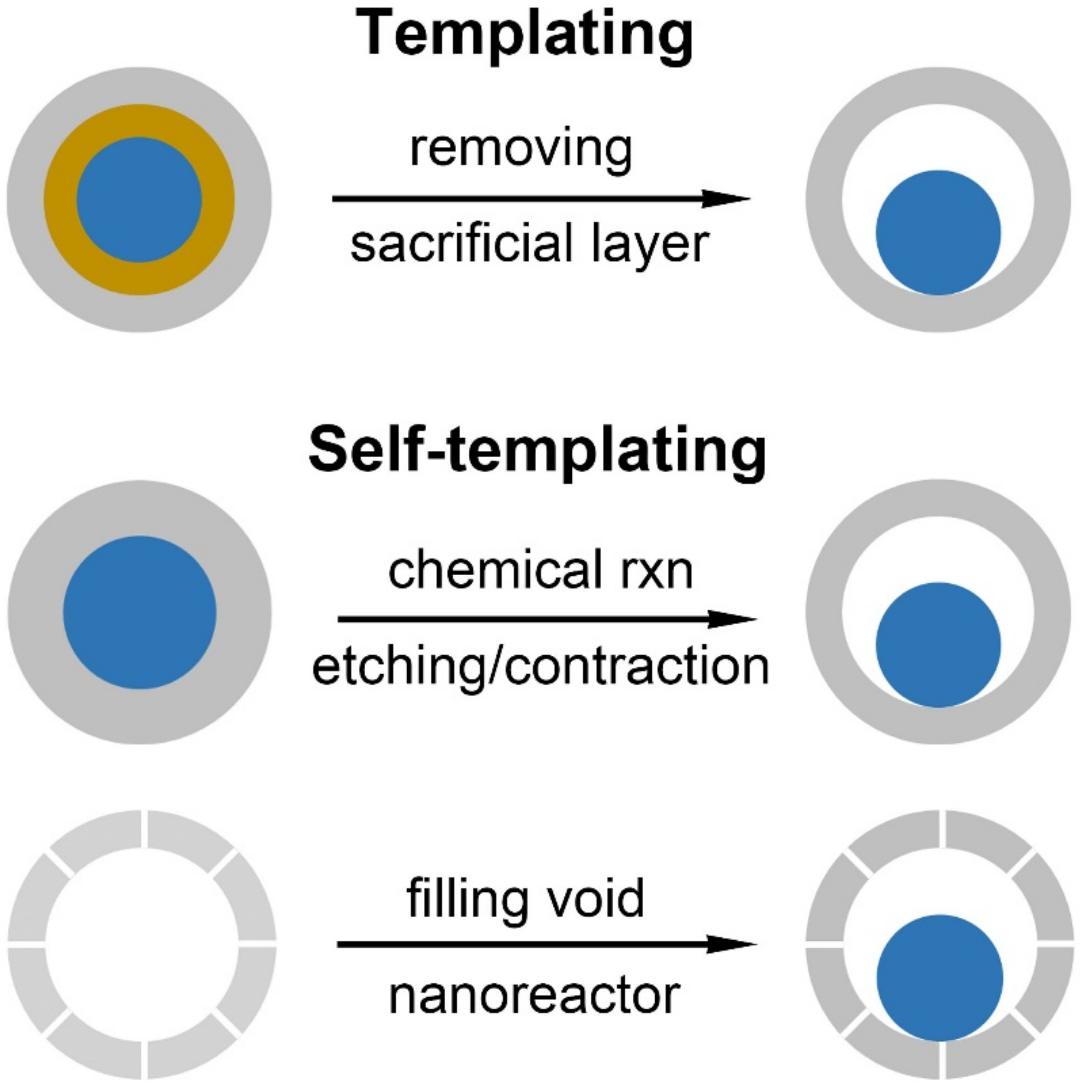
Scheme 1. Synthetic strategies towards yolk–shell nanostructures categorizing into the templating and the self-templating approaches.
Nanomaterials 10 00675 sch001
Figure 1. Templating approaches for yolk–shell nanostructures. (A) Synthetic scheme of Au@TiO2 yolk–shell nanostructure by using SiO2 as a sacrificial layer. (B,C) TEM images of the Au@TiO2 yolk–shell after etching the SiO2 layer. Reproduced with permission from [31]. Copyright Elsevier Ltd, 2016. (D) Decoration of interior surfaces in the SiO2 hollow shell by exploiting amorphous Se colloids as a template. Reproduced with permission from [35]. Copyright American Chemical Society, 2008.
Nanomaterials 10 00675 g001
Figure 2. Self-templating syntheses for yolk–shell nanostructures. (A) Scheme illustrating the procedure for the Au core and Au/Ag alloy shell through the galvanic replacement reaction. (B,C) TEM images of Au@Au/Ag yolk–shell nanostructure. Reproduced with permission from [37]. Copyright Wiley-VCH, 2016.
Nanomaterials 10 00675 g002
Figure 3. Self-templating syntheses for yolk–shell nanostructures. (AC) TEM images of the hollow mesoporous silica (HMS) containing Fe nanoparticle prepared by a sequential two solvents impregnation-reduction reaction. Reproduced with permission from [44]. Copyright American Chemical Society, 2014. (D) Preparation of polymer nanocapsules loaded with Ag nanoparticles through a free-radical photoinitiator. (E) TEM image of nanocapsules containing the Ag yolk particles. Reproduced with permission from [45]. Copyright The Royal Society of Chemistry, 2010.
Nanomaterials 10 00675 g003
Figure 4. Si@C yolk–shell nanostructure. (A) Comparison of a conventional slurry coated silicon nanoparticle and Si@C yolk–shell electrodes. SEI on the surface of the Si nanoparticles is not stable, leading to failure of the battery in a conventional slurry electrode. The yolk–shell nanostructure creates enough space and allows the Si to expand without rupturing the shell layer. (B) SEM image of Si@C yolk–shell nanostructure. (C) Serial in situ TEM images showing the expansion of the Si yolk part. The scale bar is 200 nm. (D) Delithiation capacity and Coulomb efficiency of the first 1000 galvanostatic cycles between 0.01−1 V at 1 C rate. Reproduced with permission from [18]. Copyright American Chemical Society, 2012.
Nanomaterials 10 00675 g004
Figure 5. (A) Schematic process for the formation of the mesoporous carbon-coated silicon yolk–shell nanostructure. TEM images of (B) Si@SiO2 core–shell nanoparticles, (C) Si@SiO2@mSiO2 core–shell nanoparticles, and (D) Si@mC yolk–shell nanostructure. (mSiO2: mesoporous SiO2, mC: mesoporous carbon) (E) Charge–discharge cycling performance of Si nanoparticle and carbon-coated yolk–shell nanostructure electrodes. (F) Rate performance of yolk–shell nanostructure electrode. Reproduced with permission from [63]. Copyright Elsevier Ltd, 2015.
Nanomaterials 10 00675 g005
Figure 6. (A) Schematic illustration of the formation mechanism of yolk–shell Sn@C nanostructure (in the middle). SEM (B) and TEM (C) image of the yolk–shell Sn@C spheres by eliminating Zn component. (D) Initial charge and discharge profiles of tin powder and Sn@C yolk–shell electrodes. (E) Cycling performance of the two electrodes. Reproduced with permission from [66]. Copyright Wiley-VCH, 2015.
Nanomaterials 10 00675 g006
Figure 7. (A) The formation process of the SnO2@C yolk–shell nanostructure. SEM (B) and TEM (C) images of the SnO2@C yolk–shell nanostructures. Initial charge–discharge curves (D) and cycling performance (E) of the SnO2@C yolk–shell nanostructure and hollow SnO2 particle electrodes. Reproduced with permission from [72]. Copyright The Royal Society of Chemistry, 2014.
Nanomaterials 10 00675 g007
Figure 8. (A) Synthetic step of Al@TiO2 yolk–shell nanospheres. SEM (B) and TEM (C) images of yolk–shell Al@TiO2 nanostructures. (D) Cycling performance and Coulombic efficiency at 1 C rate. Scale bars are 20 nm (B) and 10 nm (C). (E) Charge–discharge profile of the first, 250th, and 500th cycling. Reproduced with permission from [77]. Copyright Springer Nature Publishers Ltd, 2015.
Nanomaterials 10 00675 g008
Figure 9. (A) Schematic diagram of the yolk–shell NiO nanosphere by spray pyrolysis. Cycling performance (B) and rate performance (C) of the yolk–shell and single crystalline cubic NiO nanopowder electrodes in the voltage range of 0.001−3 V. Reproduced with permission from [91]. Copyright American Chemical Society, 2014.
Nanomaterials 10 00675 g009
Figure 10. (A) Schematic illustration of the formation process of yolk–shell MoO2 spheres by Ostwald ripening and the corresponding SEM and TEM images. (B) Charge–discharge voltage profiles of the yolk–shelled MoO2 electrode at different current densities. (C) Cycling performance. Reproduced with permission from [87]. Copyright The Royal Society of Chemistry, 2013.
Nanomaterials 10 00675 g010
Figure 11. (A) Schematic illustration showing the formation of FeOx@C yolk–shell nanostructure. (BE) TEM images corresponding to each step in (A): α-Fe2O3α-Fe2O3@SiO2 → FeOx@SiO2@C → FeOx@C. (F) Cycling capacity of FeOx@C yolk–shell nanostructures at 0.2 C. (G) Rate performance of FeOx@C-2. Reproduced with permission from [82]. Copyright Wiley-VCH, 2014.
Nanomaterials 10 00675 g011
Figure 12. (A) Scheme showing the formation of Fe3O4@Fe3C-C yolk–shell nanostructure. (B,C) TEM images of Fe3O4@Fe3C–C. (D) Capacity retention of the yolk–shell electrode, Fe3O4@C core–shell electrode, and pure Fe3O4 nanoparticle electrode. (E) Cycling performance of the three electrodes and Coulombic efficiency of the yolk–shell electrode. Reproduced with permission from [47]. Copyright American Chemical Society, 2015.
Nanomaterials 10 00675 g012
Table 1. Summary of various Li/Na rechargeable anode materials constructed as yolk–shell nanostructures. (Pyrolysis: spray pyrolysis, Thermal: thermal treatment, Ripening: Ostwald ripening, LTO: Li4Ti5O12).
YolkShellFabricationPros/Cons
Alloy/de-alloy materials
SiC [17,18,19,59,60,61,62,63], NiO [64], SiO2@C [65]Etching [17,18,19,60,61,62,63,65], Pyrolysis [59,64]high capacity and energy density, good safety/poor cycling
SnC [66,67,68,69,70,71]Thermal [67,68,69,70,71], Pyrolysis [66]
SnO, SnO2C [72,73,74,75], SnO2 [76]Etching [72,73], Thermal [74,75,76]
AlTiO2 [77]Etching [77]
Conversion materials
Co3O4, CoMn2O4Co3O4 [78], CoMn2O4 [79]Pyrolysis [78,79]high capacity, high energy, environmentally-compatibility/low coulombic efficiency, poor cycling, unstable SEI formation, large potential hysteresis
Cr2O3TiO2 [47]Thermal [47]
Fe2O3, Fe3O4, FeOxC [47,80,81,82], grapheme [44], Fe2O3 [83], TiO2 [84]Etching [80,81,82], Pyrolysis [83], Thermal [44,47,84]
MnO, MnO2C [85,86]Thermal [85], Etching [86]
MoO2MoO2 [87]Ripening [87]
Ni, NiO, NiMoO4, NiCO2O4C [88], graphene [89], NiO [90,91], NiMoO4 [92], NiCO2O4 [93]Etching [89], Pyrolysis [91,92], Thermal [88,90,93]
V2O3V2O3@C [94]Ripening [94]
ZnO, ZnCo2O4, ZnFe2O4, ZnO–Mn3O4C [95], ZnO–NiO [96], ZnCo2O4 [97], ZnFe2O4 [98], ZnO/Mn3O4 [99]Pyrolysis [97,98,99], Ripening [95,96]
CoS2, Co9S8CoS2 [100], Co9S8 [101]Ripening [100], Pyrolysis [101]
MoSe2MoSe2 [102]Pyrolysis [102]
SnSSnS [103]Pyrolysis [103]
Zn–Fe–SZn–Fe–S [104]Pyrolysis [104]
Insertion/de-insertion materials
TiO2, Li4Ti5O12TiO2 [105,106,107], TiO2–C [108], Li4Ti5O12 [109]Ripening [105,106,107], Pyrolysis [109]extreme safety/low capacity