Transparent Platinum Counter Electrode Prepared by Polyol Reduction for Bifacial, Dye-Sensitized Solar Cells


Abstract
1. Introduction
2. Materials and Methods
2.1. Fabrication of Pt Counter Electrodes
2.2. Characterization
2.3. Device Fabrication and Characterization
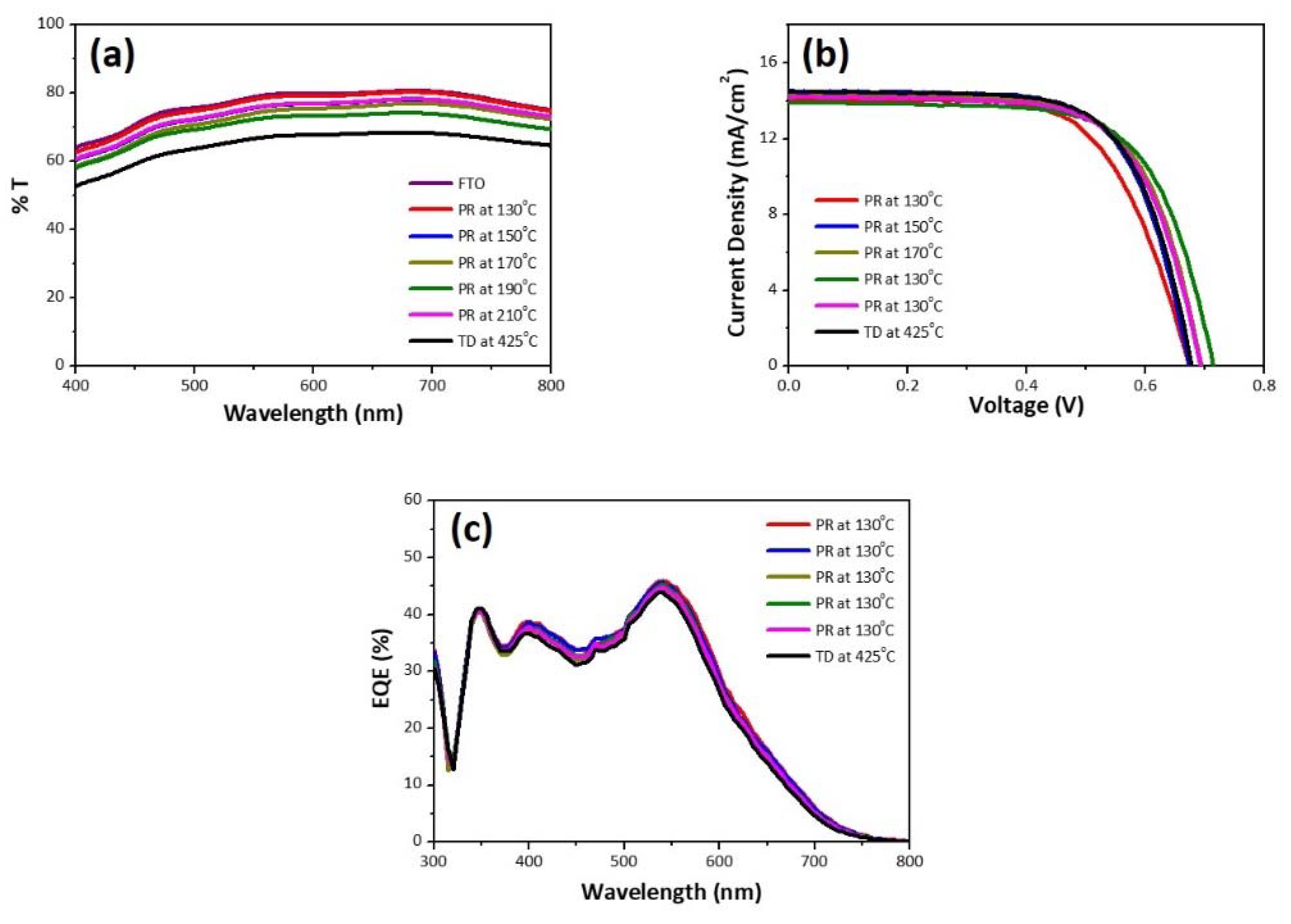
3. Results
4. Conclusions
Author Contributions
Funding
Acknowledgments
Conflicts of Interest
References
- Fakharuddin, A.; Jose, R.; Brown, T.M.; Fabregat-Santiago, F.; Bisquert, J. A perspective on the production of dye-sensitized solar modules. Energ. Environ. Sci. 2014, 7, 3952–3981. [Google Scholar] [CrossRef]
- Wu, W.; Wang, J.; Zheng, Z.; Hu, Y.; Jin, J.; Zhang, Q.; Hua, J. A strategy to design novel structure photochromic sensitizers for dye-sensitized solar cells. Sci. Rep. 2015, 5, 8592. [Google Scholar] [CrossRef] [PubMed]
- Freitag, M.; Teuscher, J.; Saygili, Y.; Zhang, X.; Giordano, F.; Liska, P.; Hua, J.; Zakeeruddin, S.M.; Moser, J.E.; Grätzel, M.; et al. Dye-sensitized solar cells for efficient power generation under ambient lightning. Nat. Photonics 2017, 11, 372–378. [Google Scholar] [CrossRef]
- Yuan, H.; Wang, W.; Xu, D.; Xu, Q.; Xie, J.; Chen, X.; Zhang, T.; Xiong, C.; He, Y.; Zhang, Y.; et al. Outdoor testing and ageing of dye-sensitized solar cells for building integrated photovoltaics. Solar Energy 2018, 165, 233–239. [Google Scholar] [CrossRef]
- Li, P.; Tang, Q. Highly transparent metal selenide counter electrodes for bifacial dye-sensitized solar cells. J. Power Sources 2016, 317, 43–48. [Google Scholar] [CrossRef]
- Kang, J.S.; Kim, J.; Kim, J.-Y.; Lee, M.J.; Kang, J.; Son, Y.J.; Jeong, J.; Park, S.H.; Ko, M.J.; Sung, Y.-E. Highly efficient bifacial dye-sensitized solar cells employing polymeric counter electrodes. ACS Appl. Mater. Interfaces 2018, 10, 8611–8620. [Google Scholar] [CrossRef]
- Bu, C.; Liu, Y.; Yu, Z.; You, S.; Huang, N.; Liang, L.; Zhao, X.-Z. Highly transparent carbon counter electrode prepared via an in situ carbonization method for bifacial dye-sensitized solar cells. ACS Appl. Mater. Interfaces 2013, 5, 7432–7438. [Google Scholar] [CrossRef]
- Zhang, Y.; Zhao, Y.; Duan, J.; Tang, Q. S-doped CQDs tailored transparent counter electrodes for high-efficiency bifacial dye-sensitized solar cells. Electrochim. Acta. 2018, 216, 588–595. [Google Scholar] [CrossRef]
- Hu, Z.; Xia, K.; Zhang, J.; Hu, Z.; Zhu, Y. Highly transparent ultrathin metal sulfide films as efficient counter electrodes for bifacial dye-sensitized solar cells. Electrochim. Acta 2015, 170, 39–47. [Google Scholar] [CrossRef]
- Bu, C.; Tai, Q.; Liu, Y.; Guo, S.; Zhao, X. A transparent and stable polypyrrole counter electrode for dye-sensitized solar cell. J. Power Sources 2013, 221, 78–83. [Google Scholar] [CrossRef]
- Li, H.; Xiao, X.; Han, G.; Hou, H. Honeycomb-like poly(3,4-ethylenedioxythiophene) as an effective and transparent counter electrode in bifacial dye-sensitized solar cells. J. Power Sources 2017, 342, 709–716. [Google Scholar] [CrossRef]
- He, B.; Zhang, X.; Zhang, H.; Li, J.; Meng, Q.; Tang, Q. Transparent molybdenum sulfide decorated polyaniline complex counter electrodes for efficient bifacial dye-sensitized solar cells. Solar Energy 2017, 147, 470–478. [Google Scholar] [CrossRef]
- Ahmed, A.S.A.; Xiang, W.; Hu, X.; Qi, C.; Amiinu, I.S.; Zhao, X. Si3N4/MoS2-PEDOT:PSS composite counter electrode for bifacial dye-sensitized solar cells. Solar Energy 2018, 173, 1135–1143. [Google Scholar] [CrossRef]
- Moraes, R.S.; Saito, E.; Leite, D.M.G.; Massi, M.; da Silva Sobrinho, A.S. Optical, electrical and electrochemical evaluation of sputtered platinum counter electrodes for dye sensitized solar cells. Appl. Surf. Sci. 2016, 364, 229–234. [Google Scholar] [CrossRef]
- Zhou, R.; Guo, W.; Yu, R.; Pan, C. Highly flexible, conductive and catalytic Pt networks as transparent counter electrodes for wearable dye-sensitized solar cells. J. Mater. Chem. A 2015, 3, 23028–23034. [Google Scholar] [CrossRef]
- Dong, H.; Chen, Y.C.; Feldmann, C. Polyol synthesis of nanoparticles: Status and options regarding metals, oxides, chalcogenides, and non-metal elements. Green Chem. 2015, 17, 4107–4132. [Google Scholar] [CrossRef]
- Fievet, F.; Ammar-Merah, S.; Brayner, R.; Chau, F.; Giraud, M.; Mammeri, F.; Peron, J.; Piquemal, J.Y.; Sicard, L.; Viau, G. The polyol process: A unique method for easy access to metal nanoparticles with tailored sizes, shapes and compositions. Chem. Soc. Rev. 2018, 47, 5187–5233. [Google Scholar] [CrossRef]
- Cho, S.J.; Ouyang, J. Attachment of platinum nanoparticles to substrates by coating and polyol reduction of a platinum precursor. J. Phys. Chem. C 2011, 115, 8519–8526. [Google Scholar] [CrossRef]
- Sun, K.; Fan, B.; Ouyang, J. Nanostructured platinum films deposited by polyol reduction of a platinum precursor and their application as counter electrode dye-sensitized solar cells. J. Phys. Chem. C 2010, 114, 4237–4244. [Google Scholar] [CrossRef]
- Cho, S.J.; Neo, C.Y.; Mei, X.G.; Ouyang, J.Y. Platinum nanoparticles deposited on substrates by solventless chemical reduction of a platinum precursor with ethylene glycol vapor and its application as highly effective electrocatalyst in dye-sensitized solar cells. Electrochim. Acta 2012, 85, 16–24. [Google Scholar] [CrossRef]
- Song, M.Y.; Chaudhari, K.N.; Park, J.; Yang, D.-S.; Kim, J.H.; Kim, M.-S.; Lim, K.; Ko, J.; Yu, J.-S. High efficient Pt counter electrode prepared by homogeneous deposition method for dye-sensitized solar cell. Appl. Energy 2012, 100, 132–137. [Google Scholar] [CrossRef]
- Decoppet, J.-D.; Moehl, T.; Babkair, S.S.; Alzubaydi, R.A.; Ansari, A.A.; Habib, S.S.; Zakeeruddin, S.M.; Schmidt, H.-W.; Grätzel, M. Molecular gelation of ionic liquid–sulfolane mixtures, a solid electrolyte for high performance dye-sensitized solar cells. J. Mater. Chem. A 2014, 2, 15972–15977. [Google Scholar] [CrossRef][Green Version]
- Leonardi, E.; Penna, S.; Brown, T.M.; Di Carlo, A.; Reale, A. Stability of dye-sensitized solar cells under light soaking test. J. Non-Cryst. Solids 2010, 356, 2049–2052. [Google Scholar] [CrossRef]
- Veerender, P.; Saxena, V.; Jha, P.; Koiry, S.P.; Gusain, A.; Samanta, S.; Chauhan, A.K.; Aswal, D.K.; Gupta, S.K. Free-standing polypyrrole films as substrate-free and Pt-free counter electrodes for quasi-solid dye-sensitized solar cells. Org. Electron. 2012, 13, 3032–3039. [Google Scholar]
- Skrabalak, S.E.; Wiley, B.J.; Kim, M.; Formo, E.V.; Xia, Y. On the polyol synthesis of silver nanostructures: Glycolaldehyde as a reducing agent. Nano Lett. 2008, 8, 2077–2081. [Google Scholar] [CrossRef] [PubMed]
- Dablemont, C.; Lang, P.; Mangeney, C.; Piquemal, J.-Y.; Petkov, V.; Herbst, F.; Viau, G. FTIR and XPS study of Pt nanoparticle functionalization and interaction with alumina. Langmuir 2008, 24, 5832–5841. [Google Scholar] [CrossRef]
- Liu, Z.; Lee, J.Y.; Chen, W.; Han, M.; Gan, L.M. Physical and electrochemical characterizations of microwave-assisted polyol preparation of carbon-supported PtRu nanoparticles. Langmuir 2004, 20, 181–187. [Google Scholar] [CrossRef]
- Wan, J.; Fang, G.; Yin, H.; Liu, X.; Liu, D.; Zhao, M.; Ke, W.; Tao, H.; Tang, Z. Pt-Ni alloy nanoparticles as superior counter electrodes for dye-sensitized solar cells: Experimental and theoretical understanding. Adv. Mater. 2014, 26, 8101–8106. [Google Scholar] [CrossRef]
- Chang, P.-J.; Cheng, K.-Y.; Chou, S.-W.; Shyne, J.-J.; Yang, Y.-Y.; Hung, C.-Y.; Lin, C.-Y.; Chen, H.-L.; Chou, H.-L.; Chou, P.-T. Tri-iodide reduction activity of shape- and composition-controlled PtFe nanostructures as counter electrodes in dye-sensitized solar cells. Chem. Mater. 2016, 28, 2110–2119. [Google Scholar] [CrossRef]
- Popoola, I.K.; Gondal, M.A.; AlGhamdi, J.M.; Qahtan, T.F. Photofabrication of highly transparent platinum counter electrodes at ambient temperature for bifacial dye sensitized solar cells. Sci. Rep. 2018, 8, 12864. [Google Scholar]


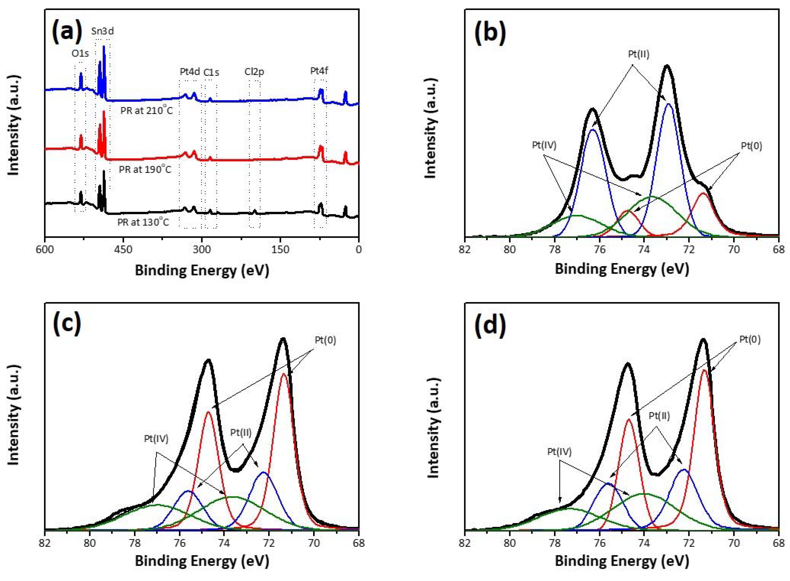
| Pt(0) | Pt(II) | Pt(IV) | |||||||
|---|---|---|---|---|---|---|---|---|---|
| 4f5/2 | 4f7/2 | S | 4f5/2 | 4f7/2 | S | 4f5/2 | 4f7/2 | S | |
| PR-130 | 74.8 | 71.4 | 23.7 | 76.3 | 72.9 | 38.8 | 77.0 | 73.7 | 37.5 |
| PR-190 | 74.7 | 71.4 | 48.4 | 75.6 | 72.3 | 22.7 | 77.0 | 73.7 | 28.9 |
| PR-210 | 74.7 | 71.4 | 44.8 | 75.6 | 72.3 | 20.9 | 77.0 | 73.7 | 34.3 |
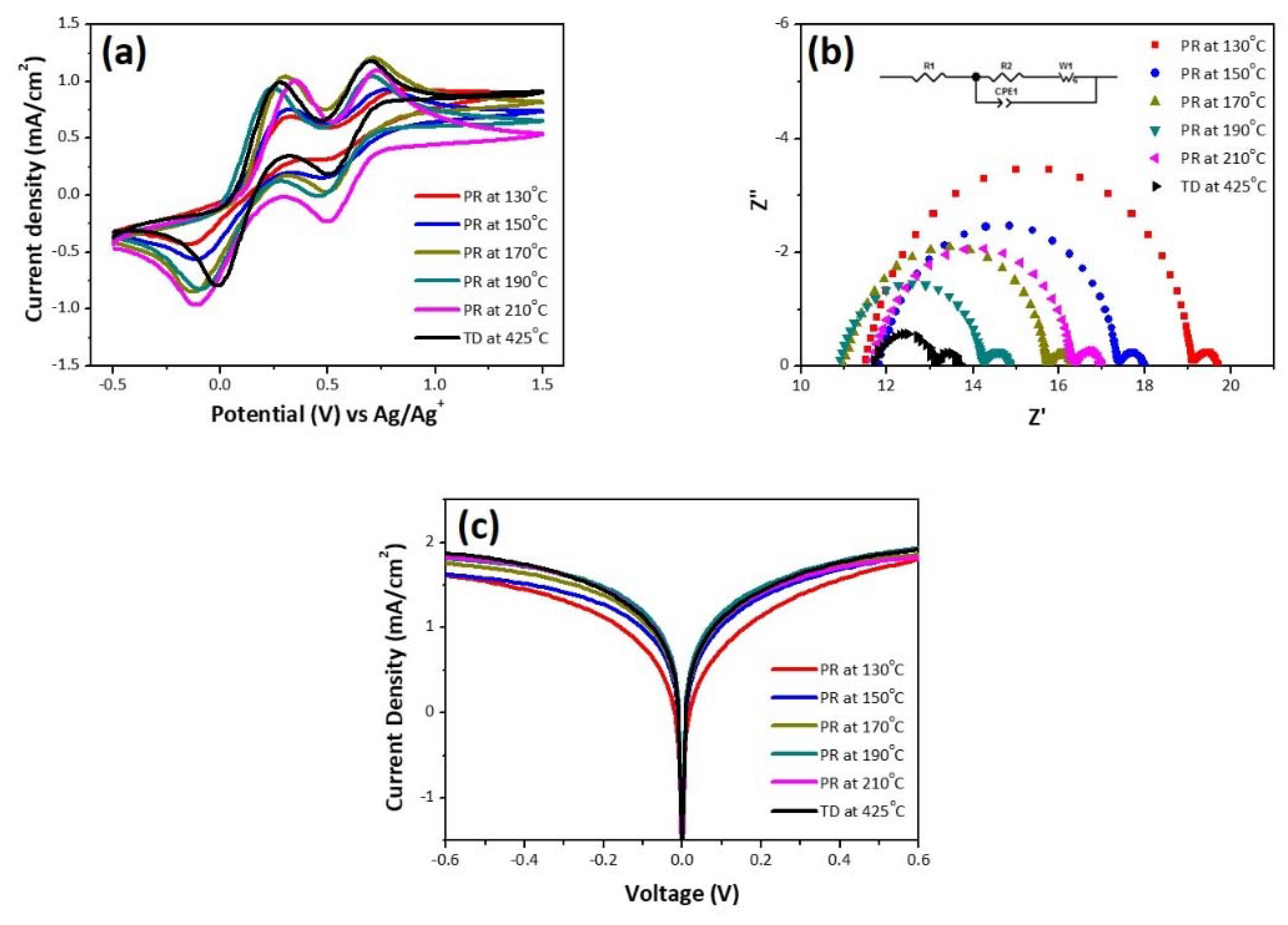
| No | ΔEp (V) | J0 (mA/cm2) | Jlim (mA/cm2) | Rs (Ω/cm2) | Rct (Ω/cm2) | ZN (Ω/cm2) |
|---|---|---|---|---|---|---|
| PR-130 | 0.47 | 4.99 | 0.21 | 8.05 | 5.19 | 0.44 |
| PR-150 | 0.44 | 9.16 | 0.21 | 8.26 | 3.79 | 0.44 |
| PR-170 | 0.43 | 11.14 | 0.24 | 7.69 | 3.21 | 0.41 |
| PR-190 | 0.35 | 14.76 | 0.26 | 7.63 | 2.23 | 0.44 |
| PR-210 | 0.46 | 12.44 | 0.26 | 8.13 | 3.17 | 0.48 |
| TD-425 | 0.29 | 11.62 | 0.27 | 11.79 | 1.27 | 0.59 |
| No | Illumination | Voc (V) | Jsc (mA/cm2) | FF (%) | η (%) | η (R) (%) |
|---|---|---|---|---|---|---|
| PR-130 | Front | 0.666 ± 0.007 | 13.82 ± 0.23 | 59.70 ± 5.48 | 5.50 ± 0.66 | 81.03 ± 1.68 |
| Back | 0.664 ± 0.008 | 10.67 ± 0.32 | 62.74 ± 4.85 | 4.45 ± 0.50 | ||
| PR-150 | Front | 0.673 ± 0.003 | 13.99 ± 0.51 | 67.45 ± 1.43 | 6.35 ± 0.33 | 77.57 ± 1.57 |
| Back | 0.670 ± 0.004 | 10.65 ± 0.62 | 69.04 ± 1.22 | 4.93 ± 0.35 | ||
| PR-170 | Front | 0.694 ± 0.006 | 13.96 ± 0.31 | 67.20 ± 1.33 | 6.51 ± 0.30 | 76.73 ± 1.33 |
| Back | 0.689 ± 0.003 | 10.62 ± 0.52 | 68.28 ± 0.90 | 5.00 ± 0.30 | ||
| PR-190 | Front | 0.702 ± 0.011 | 13.77 ± 0.12 | 67.66 ± 1.55 | 6.55 ± 0.28 | 76.61 ± 3.24 |
| Back | 0.699 ± 0.00 | 10.44 ± 0.23 | 68.71 ± 1.76 | 5.01 ± 0.24 | ||
| PR-210 | Front | 0.695 ± 0.004 | 13.76 ± 0.45 | 67.02 ± 0.84 | 6.41 ± 0.29 | 76.70 ± 2.14 |
| Back | 0.692 ± 0.008 | 10.42 ± 0.68 | 68.22 ± 0.94 | 4.92 ± 0.3 | ||
| TD-425 | Front | 0.682 ± 0.00 | 13.97 ± 0.46 | 67.36 ± 0.72 | 6.42 ± 0.28 | 67.92 ± 2.66 |
| Back | 0.672 ± 0.005 | 9.40 ± 0.16 | 68.97 ± 0.66 | 4.35 ± 0.05 |
| Material | Method | T (%) | Voc (V) | Jsc (mAcm−2) | FF (%) | η (front) (%) | η (back) (%) | η (R) (%) | Refs. |
|---|---|---|---|---|---|---|---|---|---|
| PEDOT | Electropolymerization | ~90 a | 0.751 | 14.60 | 67 | 7.40 | 5.23 | 70.7 | [6] |
| Carbon | Carbonization | ~75 | 0.721 | 10.52 | 60 | 6.07 | 5.04 | 83.0 | [7] |
| Ni3S4 | Hydrothermal | ~70 | 0.700 | 13.58 | 65 | 6.56 | 4.86 | 73.9 | [9] |
| PANI/MoS2 | Composite | ~63 | 0.799 | 17.93 | 63 | 7.99 | 3.40 | 42.6 | [12] |
| Pt | Photo-reduction | ~95 | 0.810 | 13.53 | 66.6 | 7.29 | 5.85 | 80.3 | [30] |
| Pt | Thermal decomposition | ~80 a | 0.757 | 15.00 | 70.7 | 8.02 | 4.43 | 55.2 | [30] |
| Pt | Polyol reduction b | ~80 | 0.702 | 13.77 | 67.6 | 6.55 | 5.01 | 76.6 | - |
© 2020 by the authors. Licensee MDPI, Basel, Switzerland. This article is an open access article distributed under the terms and conditions of the Creative Commons Attribution (CC BY) license (http://creativecommons.org/licenses/by/4.0/).
Share and Cite
Ghifari, A.; Long, D.X.; Kim, S.; Ma, B.; Hong, J. Transparent Platinum Counter Electrode Prepared by Polyol Reduction for Bifacial, Dye-Sensitized Solar Cells. Nanomaterials 2020, 10, 502. https://doi.org/10.3390/nano10030502
Ghifari A, Long DX, Kim S, Ma B, Hong J. Transparent Platinum Counter Electrode Prepared by Polyol Reduction for Bifacial, Dye-Sensitized Solar Cells. Nanomaterials. 2020; 10(3):502. https://doi.org/10.3390/nano10030502
Chicago/Turabian StyleGhifari, Alvien, Dang Xuan Long, Seonhyoung Kim, Brian Ma, and Jongin Hong. 2020. "Transparent Platinum Counter Electrode Prepared by Polyol Reduction for Bifacial, Dye-Sensitized Solar Cells" Nanomaterials 10, no. 3: 502. https://doi.org/10.3390/nano10030502
APA StyleGhifari, A., Long, D. X., Kim, S., Ma, B., & Hong, J. (2020). Transparent Platinum Counter Electrode Prepared by Polyol Reduction for Bifacial, Dye-Sensitized Solar Cells. Nanomaterials, 10(3), 502. https://doi.org/10.3390/nano10030502