Article

Self-Assembled Few-Layered MoS2 on SnO2 Anode for Enhancing Lithium-Ion Storage

Department of Chemical and Biological Engineering, Gachon University, Seongnam-si, Gyeonggi-do 13120, Korea
*
Author to whom correspondence should be addressed.
Nanomaterials 2020, 10(12), 2558; https://doi.org/10.3390/nano10122558
Submission received: 2 December 2020 / Revised: 14 December 2020 / Accepted: 18 December 2020 / Published: 20 December 2020
(This article belongs to the Special Issue Nanomaterials for Ion Battery Applications)

Abstract

:
SnO2 nanoparticles (NPs) have been used as reversible high-capacity anode materials in lithium-ion batteries, with reversible capacities reaching 740 mAh·g−1. However, large SnO2 NPs do not perform well in charge–discharge cycling. In this work, we report the incorporation of MoS2 nanosheet (NS) layers with SnO2 NPs. SnO2 NPs of ~5 nm in diameter synthesized by a facile hydrothermal precipitation method. Meanwhile, MoS2 NSs of a few hundreds of nanometers to a few micrometers in lateral size were produced by top-down chemical exfoliation. The self-assembly of the MoS2 NS layer on the gas–liquid interface was first demonstrated to achieve up to 80% coverage of the SnO2 NP anode surface. The electrochemical properties of the pure SnO2 NPs and MoS2-covered SnO2 NP anodes were investigated. The results showed that the SnO2 electrode with a single-layer MoS2 NS film exhibited better electrochemical performance than the pure SnO2 anode in lithium storage applications.

Graphical Abstract

1. Introduction

The use of lithium-ion batteries (LIBs) helps to solve issues of energy and powering devices in modern life and industries. The prevalence of electronic devices in life and the rapid development of industry have led to a demand for higher-quality energy storage systems with improvements such as higher capacity, greater stability, and improved safety. Currently, commercialized LIBs use lithium–nickel–manganese–cobalt oxide cathodes, which are generally stable but difficult to improve, and graphite anodes, which have a low capacity of ~372 mAh·g−1 [1,2]. The issues requiring attention in the development of LIBs are low anode capacity, degradation, and mechanical instability in LIB structures due to anode material expansion by the insertion and extraction of lithium ions. To improve LIB characteristics, several anode materials have been considered, such as metal alloys, metal oxides, and transition metal chalcogenides (TMCs) [3,4,5]. Recently, the use of metal oxide materials such as TiO2, SnO2, Fe2O3, and V2O5 for lithium-ion storage anodes has attracted much attention owing to their chemical stability and high reversible capacity [6,7,8,9,10,11,12,13,14,15]. Among them, SnO2 nanoparticles (NPs) have shown promising lithium-ion storage capability with very high capacity reaching 740 mAh·g−1 [16,17]. It has been reported that the required SnO2 material size is approximately 3 nm to achieve a high reversible capacity [16]. However, the lithiation process of SnO2 leads to large volume expansion, which results in poor reversible cycling performance [18]. Many methods have been employed to enhance the reaction stability of SnO2 materials by using carbon-based support materials such as amorphous carbon or graphene, as well as MoS2. For example, Lou et al. used carbon-supported SnO2 nanocolloids prepared by a facile hydrothermal method and carbonization [19]. Wang et al. developed a SnO2–graphene composite material for high-capacity reversible LIBs, which had a capacity of ~440 mAh·g−1 after 100 cycles [20]. Chen et al. reported a composite of SnO2 and MoS2 nanosheets (NS) as a LIB anode to diminish the volume expansion during lithiation in SnO2 NPs [21]. However, the appropriate working conditions and optimization of the SnO2 morphologies still require investigation and remain challenging in realizing commercial batteries.
Along with the development of metal oxide materials, 2D materials such as graphene and TMCs have drawn great attention owing to their superior properties and flexibility [22,23,24,25,26]. Single- and few-layered TMCs, including MoS2 and WS2, have revealed superior electronic and mechanical properties. They have also been utilized in many optical and electrical devices such as solar cells, light-emitting diodes, and transistors, as well as applications in catalysts for hydrogen generation and energy-storage applications in LIBs or sodium-ion batteries [27,28,29,30]. MoS2 in 1T phase has been used to overcome charge–discharge decay and to effectively store lithium or sodium ions with the aid of carbon derivatives such as graphite, carbon nanotubes (CNTs), and graphene. For instance, a combination of CNTs and 1T-structured MoS2 reported by Nguyen et al. [14] was introduced to develop 3D MoS2@graphite-CNT for a long-term stable anode material with a very high lithium-ion storage capacity. The 3D-structured MoS2@gaphite-CNT was prepared by a scalable ball-milling method. This 3D structure allowed a high anodic charge–discharge rate and showed a high capacity of ~1200 mAh·g−1 after 450 cycles. Moreover, Lane et al. reported the computed electronic structure of lithium- and sodium-intercalated MoS2. They concluded that the 1T-MoS2 could be a high-capacity and high-conductivity anode material [31]. Li et al. also discovered that the growth of 3D bulky MoS2 in the 1T phase supported prolonged anodic cycling, where the structure helped to release strain during cycling and led to improved capacity at high current rates [32]. Therefore, the use of 1T-MoS2, which has high conductivity and flexibility, can help traditional anode materials exhibit superior performance in lithium storage applications.
In this work, we first demonstrated the use of a 1T-MoS2 self-assembling layer as protection on the SnO2 surface. The MoS2 NS layer was formed by using the gas–liquid interface method, which is well-known for the thin-film preparation of monolayer colloidal crystals such as polystyrene NPs [33,34,35]. SnO2 NPs were fabricated by a facile hydrothermal method. The presence of the 1T-MoS2 layer greatly enhanced the cycling performance of SnO2 anodes in LIBs. Moreover, the effect of different numbers of MoS2 layers was also investigated.

2. Experimental

2.1. Chemical Materials

Molybdenum(VI) sulfide (MoS2, powder), tin(II) chloride dihydrate (SnCl2·2H2O, powder), polyvinylidene fluoride (PVDF, MW 534,000), Sodium dodecylbenzensulfonate (technical grade) and a 2.5-M solution of n-butyllithium in hexane were purchased from Sigma-Aldrich Inc. (St. Louis, MO, USA). Super-P amorphous carbon black (C, approximately 40 nm, 99.99%) and absolute ethanol (C2H5OH) were purchased from Alpha Aesar Inc. (Ward Hill, MA, USA). All chemicals were used as delivered without any purification.

2.2. Exfoliation of MoS2 Nanosheets (NSs)

MoS2 NSs were synthesized using the liquid chemical exfoliation method [36,37,38]. In brief, 1 g of MoS2 powder was placed in a 10-mL vessel. Then, 3 mL of butyllithium in hexane was added to reach the powder level. The solution was kept for 2 days to allow lithium intercalation into the MoS2 to form LixMoS2 (x > 1) [36,39]. For the exfoliation of MoS2, LixMoS2 was washed with hexane to remove excess butyllithium by centrifugation at 5000 rpm for 5 min. The LixMoS2 obtained was exfoliated in 100 mL deionized (DI) water in a sonication bath for 1 h. The floating large-sized MoS2 in the solution was removed. Then, 1T-MoS2 was centrifuged with DI water four times and kept in DI water for further use or dried at 60 °C in a vacuum oven for characterization.

2.3. SnO2 Nanoparticle (NP) Synthesis

SnO2 NPs were prepared by a facile hydrothermal method. In a typical synthesis, 0.9 g of SnCl2·2H2O was dissolved in 100 mL of DI water under stirring for 30 min. Then, 10 mL of 10% ammonia solution (NH4OH) was dropped slowly to obtain a gel form. The solution was then transferred to a Teflon autoclave line and heated at 200 °C for 2 h. The white precipitate, SnO2, was collected via centrifugation and washing for 3 times, then dried and calcinated in air at 600 °C for 1 h.

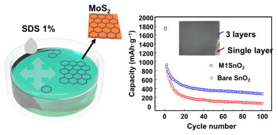
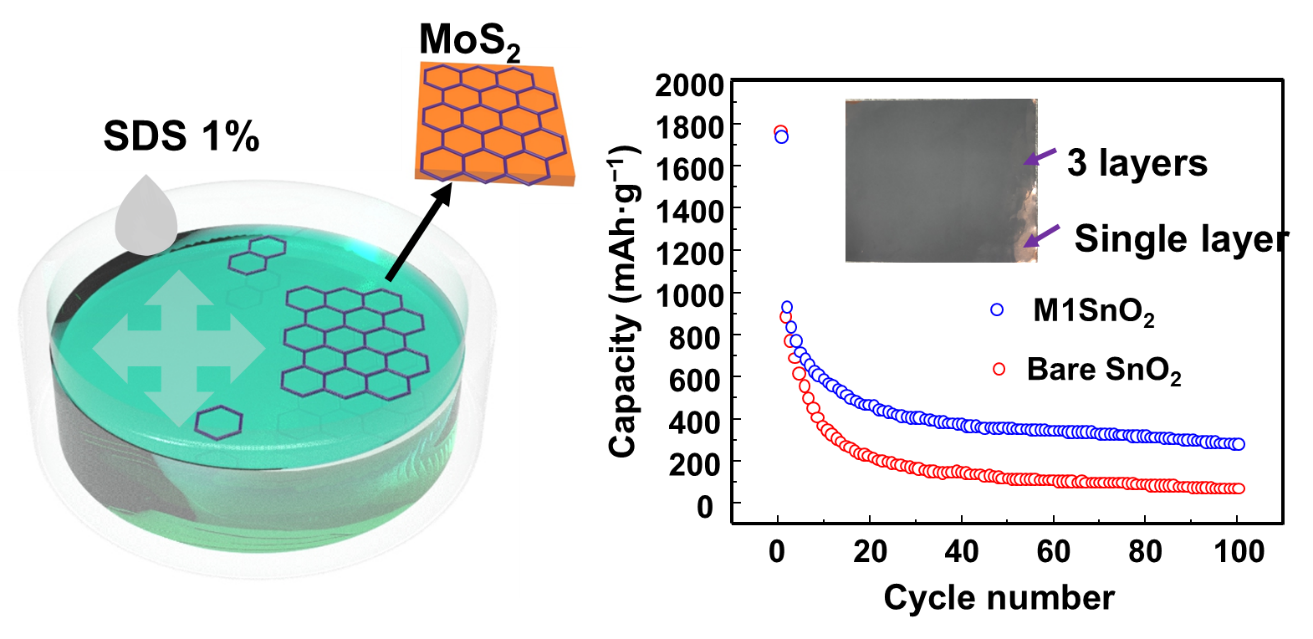
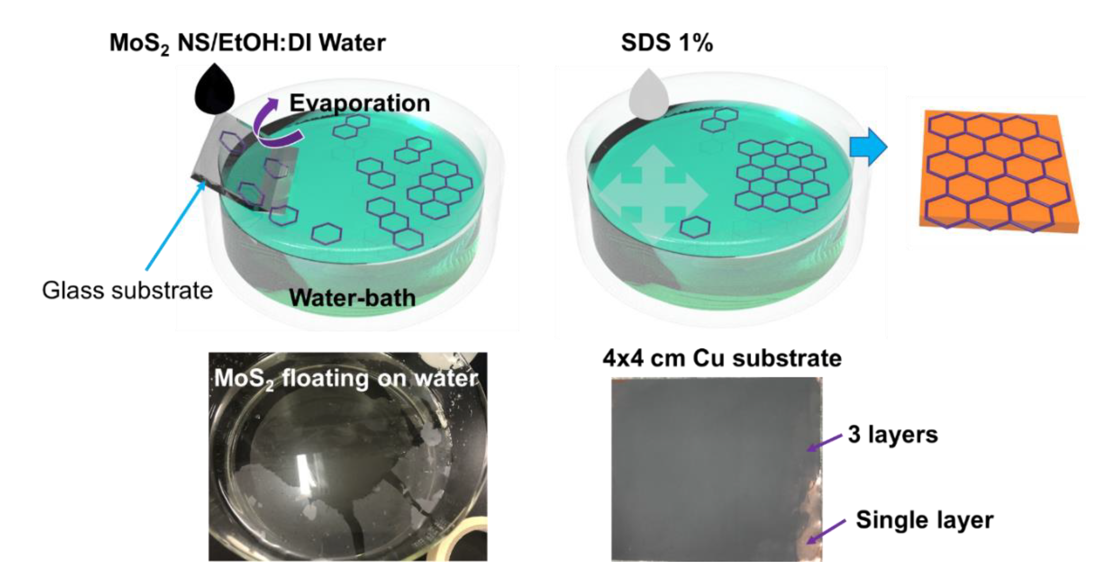
2.4. Self-Assembled MoS2 NS Layer

The self-assembled MoS2 was prepared based on the wettability of the MoS2 NSs. MoS2 NSs can be dispersed in DI water; however, an NS floats on the surface of DI water if only one NS surface is wetted. This behavior is similar to that of graphene or polystyrene, both of which can assemble as 2D layers floating on a solution. Here, MoS2 NSs were dispersed in a 1:1 volumetric DI water–ethanol mixture at a concentration of 2 mg·mL−1. A water bath and half-dipped glass substrate are shown in Figure 1. The prepared solution was then dropped slowly to allow evaporation of the DI water–ethanol solution as the drop met the water surface. The MoS2 NSs remained randomly floating at the water–air interface. To consolidate the single-layer MoS2 NSs, a ~10-μL drop of 1% sodium dodecylbenzensulfonate solution was spread on the surface to increase the surface tension. This formed a semi-transparent layer of MoS2 on the side of the water bath. The dried anode material was dipped in DI water before it was dipped in the assembled MoS2 NS layer bath. The MoS2 NS layers were easily deposited on the electrode surface. Finally, the anode was obtained by drying in a vacuum oven at 70 °C.

2.5. Characterization

X-ray diffraction (XRD) (D/MAX-2200 Rigaku, Tokyo, Japan) was used to investigate the structures of the powder samples. The XRD patterns of the samples were performed over the 2θ range of 10−70°. The structures, morphologies, and sizes of the materials were analyzed by scanning electron microscopy (SEM) (Hitachi S4700, Tokyo, Japan) and transmission electron microscopy (TEM) integrated with energy-dispersive X-ray spectroscopy (EDS) (TECNAI G2F30, FEI Corp., OR, USA).

2.6. Electrochemical Measurements

The SnO2 NP materials were employed to assemble a half-cell LIB using coin-type cells (CR 2032, Rotech Inc., Gwangju, Korea). The assembly process follows a typical LIB construction method. The working electrode was prepared by pasting a slurry of 70% active material (SnO2 NP powder), 15% PVDF, and 15% Super P in N-methyl-2-pyrrolidinone on a Cu foil by doctor blading. The electrode was then dried in a vacuum oven at 70 °C for at least 12 h before use. The MoS2 NS layer was lifted from the water surface, as mentioned before, and dried before cell assembly. Electrodes with one, two, and three MoS2 NS layers were denoted as M1SnO2, M2SnO2, and M3SnO2, respectively. The anodes were punched into circular discs of 12 mm in diameter. The areal loading of active materials was 0.84–1.05 mg cm−2. The battery half-cell structures were assembled under a neutral gas of Ar in a glovebox with positive pressure to ambient air conditions. The reference electrode, separator, and electrolyte were lithium foil, polyethylene, and 1-M LiPF6 in ethylene carbonate–diethylene carbonate (1:1 by volume), respectively. The galvanostatic electrochemical charge–discharge performances of the different cells were measured using a battery cycle tester (WBCS3000, WonAtech, Seocho-gu, Seoul) over the voltage range of 0.01–3.0 V versus Li/Li+. Cyclic voltammetry (CV) tests and electrochemical impedance spectroscopy (EIS) were performed using a ZIVE MP1 (WonAtech, Seocho-gu, Seoul) over the voltage range of 0.01–3.0 V at a scanning rate of 0.1 mV·s−1 and over the frequency range of 100 kHz–0.1 Hz.

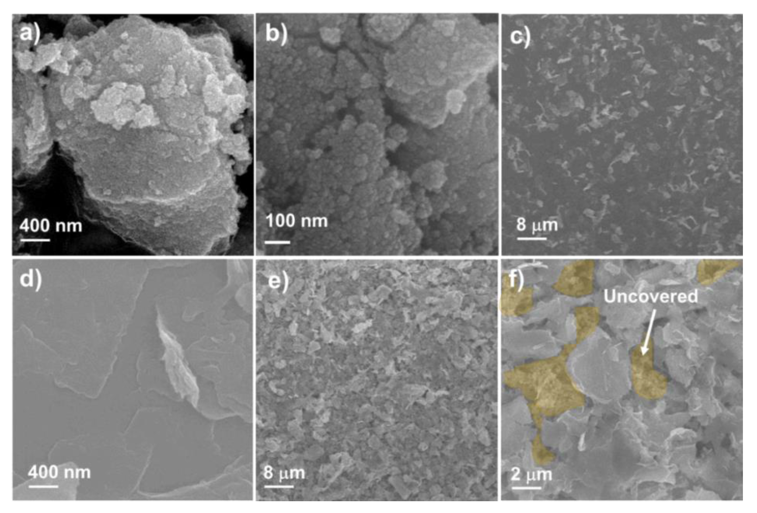
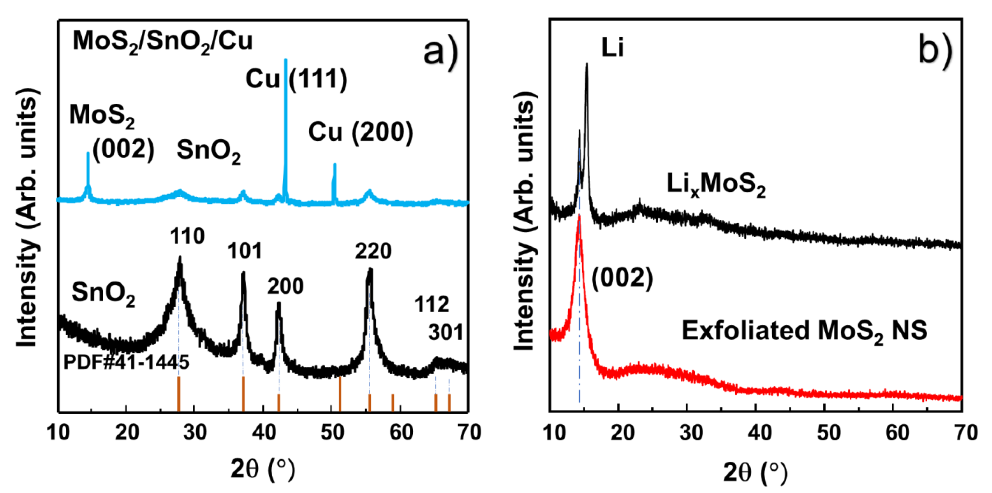
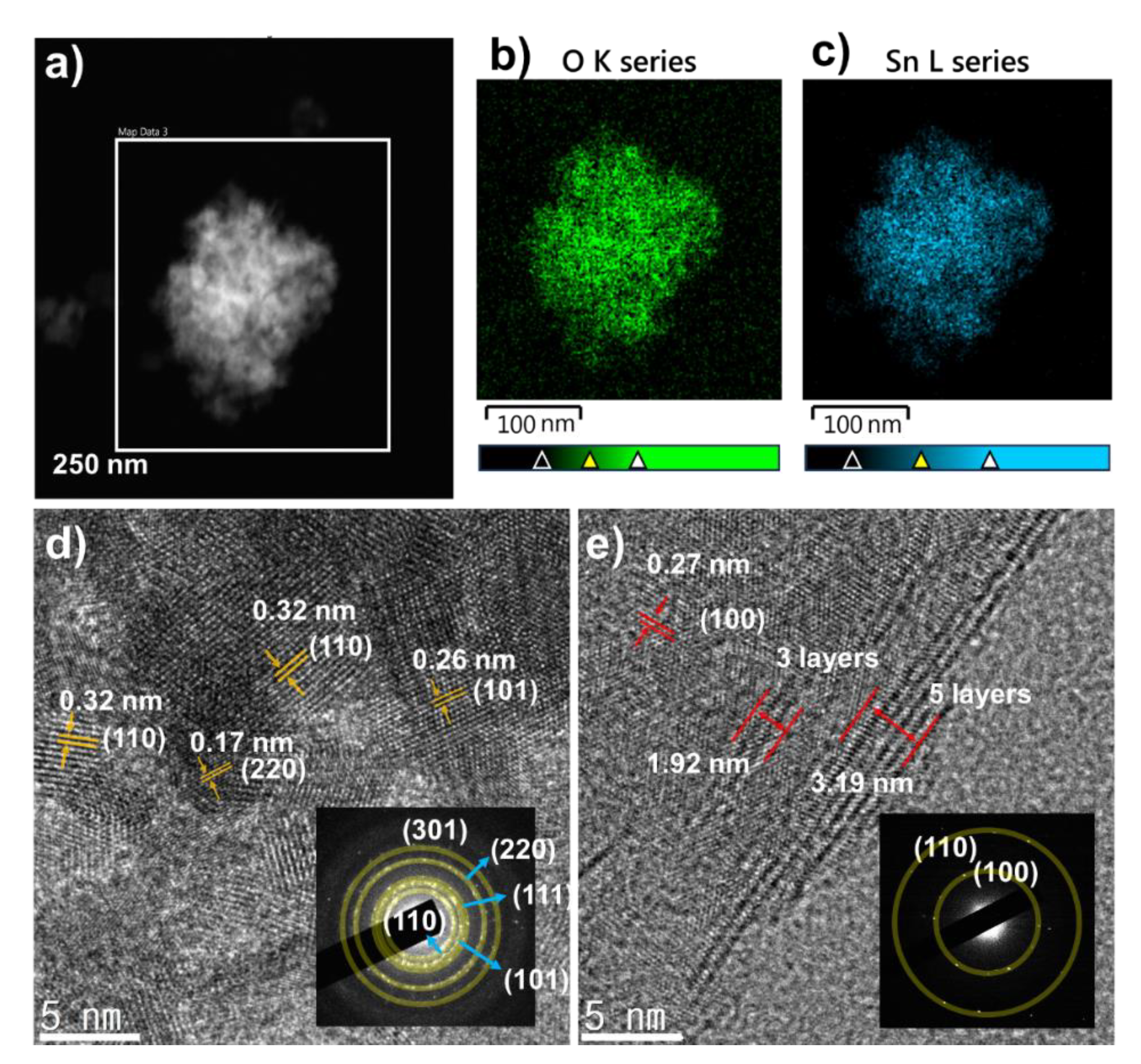
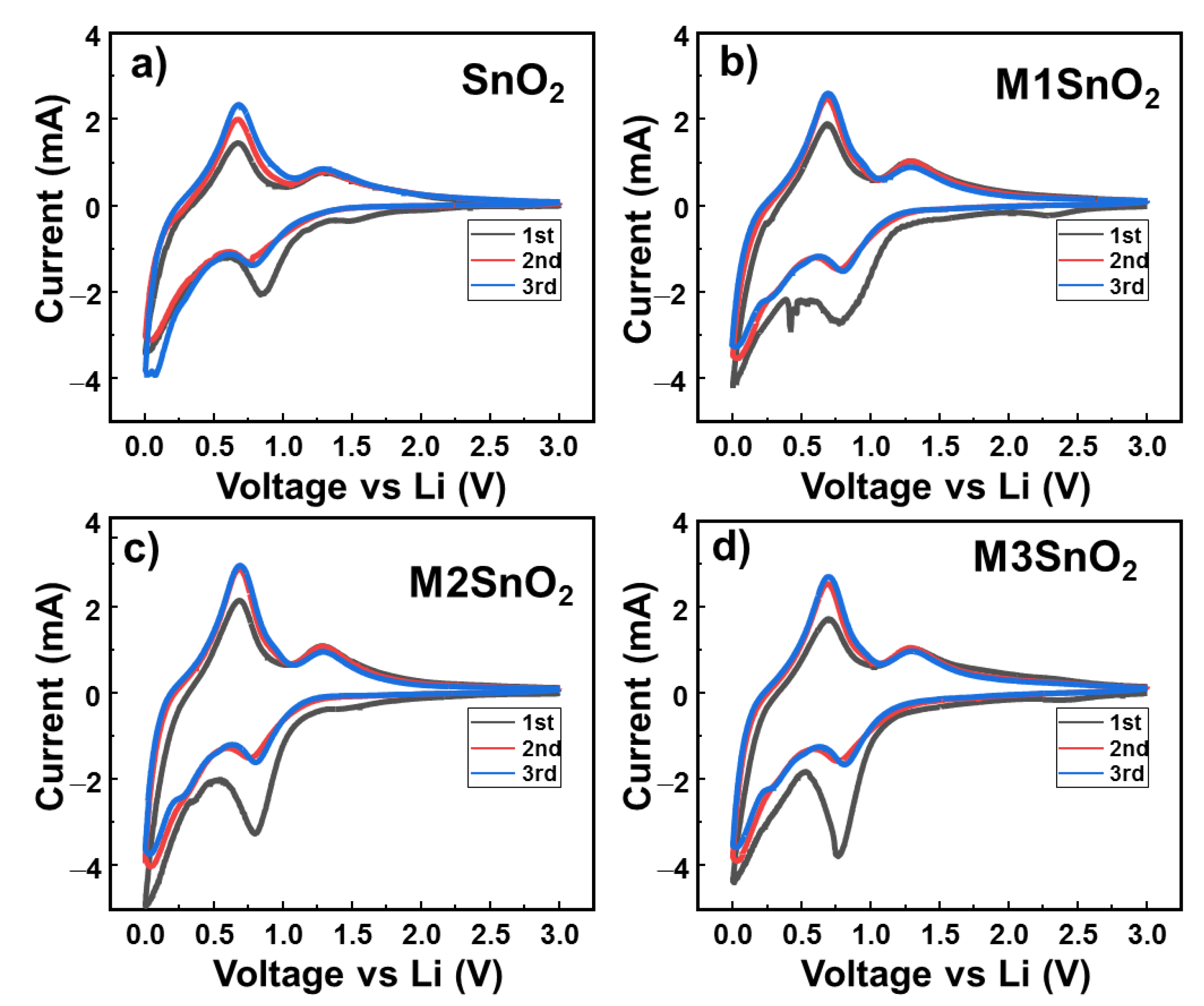
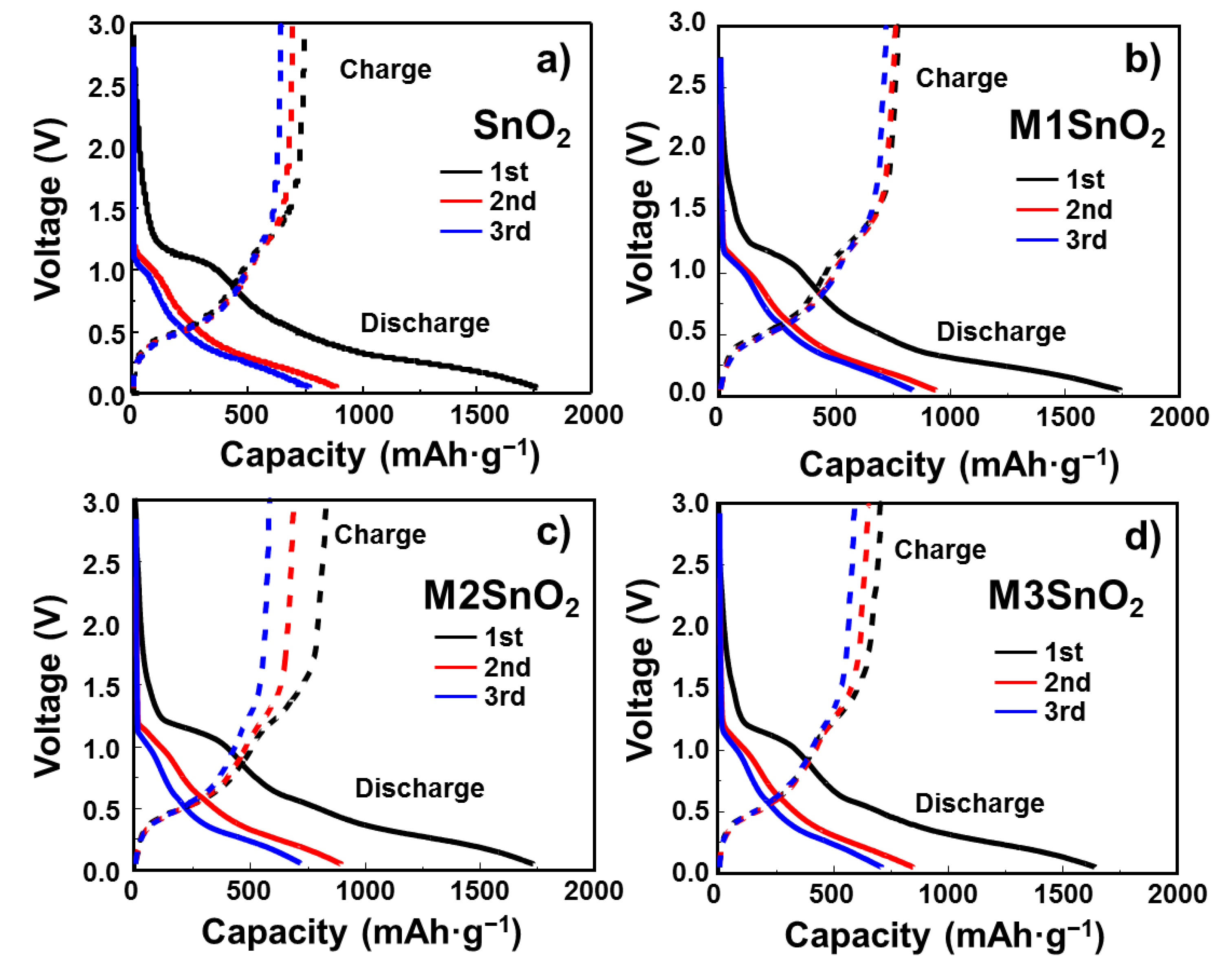
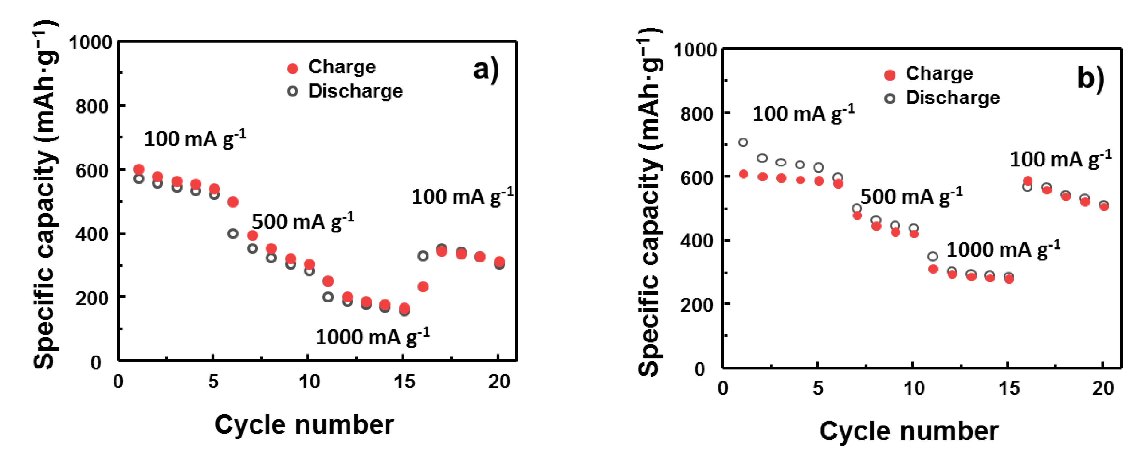
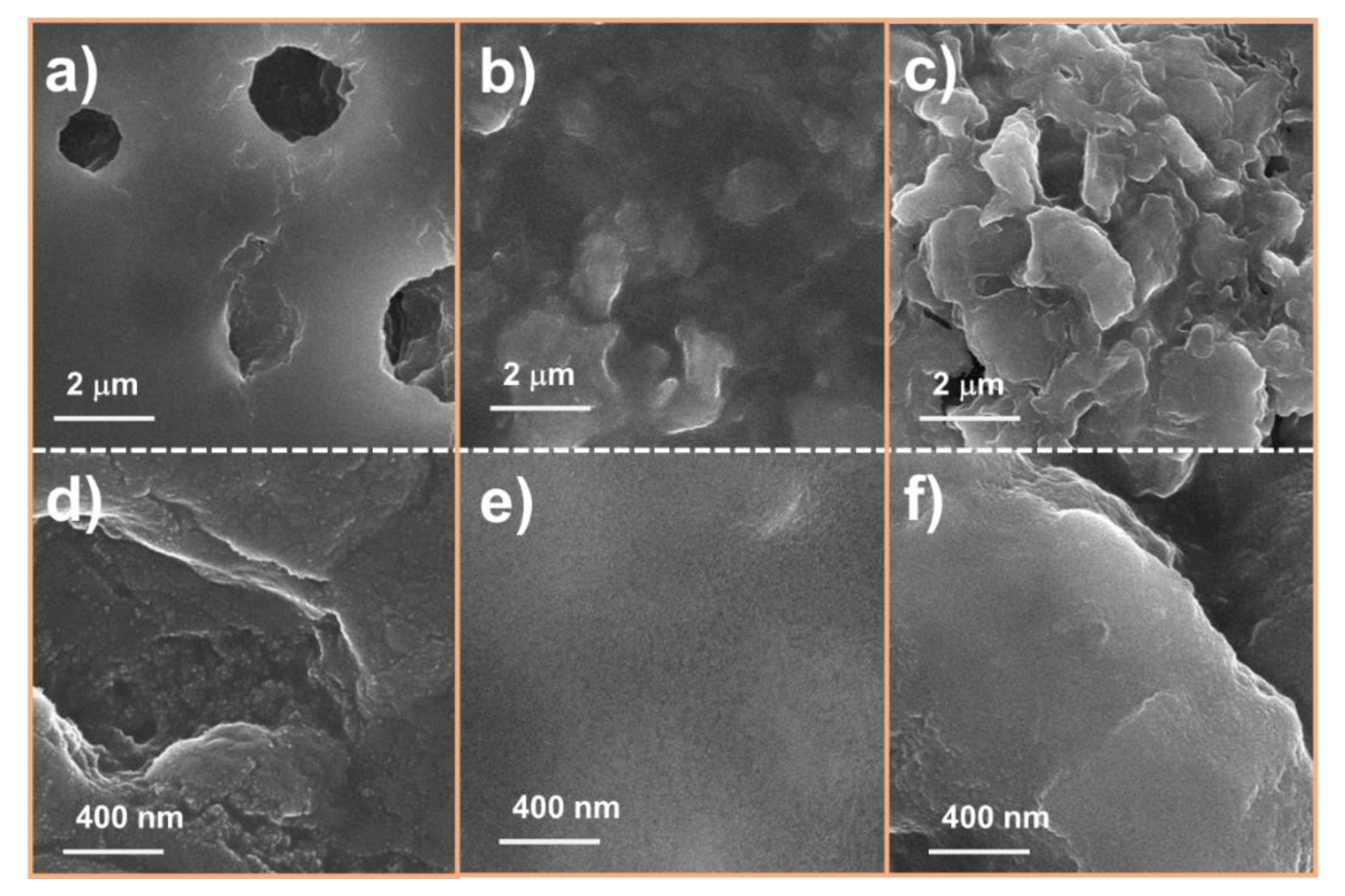
3. Results and Discussion

Figure 2 shows the SEM images of the SnO2 NP, MoS2 NS, and SnO2 anode covered with the MoS2 NS layer. To prepare the SnO2 NPs, an easy hydrothermal method was selected to obtain a uniform and highly crystalline material [40,41,42]. Sn(OH)x precipitation using NH4OH solution and hydrothermal processing were applied to develop the crystalline structures of the SnO2 NPs. It was observed that the size of the NPs was <100 nm. However, the detailed size distribution of the NPs cannot be determined by SEM measurement, as illustrated in Figure 2a,b. The diameters of the SnO2 NPs are discussed later via TEM analyses. Meanwhile, the MoS2 NSs were well prepared with lateral sizes ranging from a few hundred nanometers to a few micrometers, as shown in Figure 2c,d. The size of the NSs is larger than that of MoS2 fabricated by ultrasonication or ball milling [43,44]. The low-magnification SEM image shows that the MoS2 NSs uniformly cover the Cu electrode. Figure 2e,f shows a single-layer MoS2 NS thin film on the surface of the SnO2 electrode. It was calculated that the MoS2 NSs covered approximately 80% of the SnO2 electrode surface. The semi-transparent yellow indicates the uncovered electrode surface (Figure 2f), while the dark colors indicate the thin MoS2 layer covering the surface. From analysis of the SEM images, a novel SnO2 electrode uniformly covered with MoS2 NSs layers was prepared, from which better electrochemical performance is expected, compared to that of a pure SnO2 electrode.
To confirm the crystalline nature of the SnO2 NPs, powder XRD measurements were performed in the range of 10–70°, as shown in Figure 3a. In comparison with PDF #41-1445, the XRD pattern of the SnO2 NPs was in good agreement with the P42/mnm space group [16]. No impurity peaks appear in the pattern. This confirmed the high crystallinity of the SnO2 NPs. Furthermore, the average sizes of the crystals (D) can be calculated using the Scherrer equation:
D = 0.9λ/βcosθ
where λ is the X-ray wavelength of the XRD measurement, θ is the Bragg angle, and β is the full width at half maximum of the peak. Based on this information, the calculated crystal size of the SnO2 NPs was ~2–5 nm. The structure of the assembled MoS2 layer on SnO2 anode was also analyzed by XRD as shown in Figure 3a. The peaks of MoS2 NS, SnO2 and Cu were clearly revealed, indicating successful coverage of MoS2 on the SnO2 anode. Figure 3b shows the XRD patterns of LixMoS2 and the MoS2 NSs. The intercalation of lithium in the interface of each layer MoS2 introduced a peak at ~15.4°. After exfoliation in DI water, only the peak of (002) MoS2 remained, indicating the 2D structure of the MoS2 NSs. The size of MoS2 based on the (002) plane was calculated to be ~1 nm, illustrating the formation of thin and single- or few-layered MoS2 NSs [37,38]. The nanoscale sizes of the SnO2 NPs are promising for achieving the critical size of SnO2 that yields the best electrochemical performance. Moreover, high-quality single- and few-layer MoS2 with large lateral sizes effectively cover the electrode surface.
To further confirm the sizes and structures of the SnO2 NPs, the SnO2 powder was observed by TEM. Figure 4a–c shows the SnO2 EDS mapping images, where clear contrasts indicating Sn and O atoms were detected, indicating the high purity of the synthesized materials. In addition, the high-resolution TEM (HRTEM) image (Figure 4d) clearly shows the lattices of SnO2 NPs with (101), (110), and (220) planes with sizes of ~5 nm. This result agrees well with the calculation of the SnO2 crystal size from the XRD patterns. Furthermore, the selected-area electron diffraction (SAED) pattern in Figure 4d also confirms the lattice planes from the crystal structures, as marked with semi-transparent yellow circles. No other elements were found as contaminants. Therefore, pure SnO2 NPs were well prepared with a diameter of ~5 nm, which would contribute to a high performance in LIBs. Meanwhile, the morphology of MoS2 NS was also confirmed by HRTEM (Figure 4e), where a lattice spacing of 0.27 nm can be assigned to (100) plane. The spacing between lattice fringes in HRTEM image were to be 1.92 and 3.19 nm for 3 and 5 layers of MoS2, respectively. Furthermore, the SAED as an inset of Figure 4e also confirmed the high crystallinity of the MoS2 layer. Therefore, it can be considered that the MoS2 NS was successfully exfoliated to single- and few-layer MoS2.
To understand the effect of the MoS2 NS layer on the electrochemical properties of the SnO2 anode, CV tests were performed between 0.01 and 3.00 V (vs. Li/Li+) at a scanning rate of 0.1 mV·s−1. The electrochemical process in the anode can be expressed by the following reaction equations:
Li +   +   e   +   electrolyte   SEI   layer
SnO 2 + 4 Li + + 4 e Sn + 2 Li 2 O
Sn + x Li + + x e Li x Sn   ( 0 x 4.4 )
Equation (2) relates to the formation of a solid electrolyte (SEI) layer formed from the first lithium-ion insertion. Meanwhile, Equation (3) is the conversion reaction of SnO2 to Sn. Both reactions (2) and (3) contribute to the irreversible capacity of the anode. Reaction (4) represents the reversible reaction of Sn with lithium ions. Figure 5a shows the electrochemical performance of the pure SnO2 anode in the initial three cycles. The peak at ~0.84 V in the first cathodic cycle is attributed to the reduction of SnO2 to Sn metal and the formation of the SEI layer, as illustrated in Equations (2) and (3). In the 2nd and 3rd cycles, these peaks showed reduced intensity and were shifted to the lower potential of ~0.75 V. In the oxidation process, two peaks appear at approximately 0.67 and 1.30 V. Interestingly, the oxidation peak at 0.67 V increases in intensity as the cycle number was increased. This phenomenon could be explained by the activation of the reversible reaction that occurred in the electrode materials [17]. Meanwhile, the oxidation peak at 1.30 V was ascribed to the oxidation of metallic Sn to SnO2, which is the reversible case of reaction (2) [17,20,45]. When the MoS2 NS layer was added to the SnO2 anode surface, the CV profiles changed depending on the number of layers, as shown in Figure 5b–d, respectively. First, it is easily observed that the oxidation peaks remain stable, with two peaks at 0.67 and 1.30 V related to the reversible reduction and oxidation reaction of Sn metal. With the M1SnO2 electrode, additional peaks appeared at ~0.42 V and 0.45 V, arising from the conversion reaction as: LixMoS2 + (4 − x) Li+ + (4 − x) e → Mo + 2 Li2S and from SEI layer formation on the MoS2 materials [46,47,48,49]. The M2/M3SnO2 electrodes also have peaks at ~0.42 V; however, the intensities are weaker than that of the M1SnO2 electrode. This can be explained by the energy barrier of the single-layer MoS2 for lithium-ion intercalation, which is in the range of ~0.42 to ~0.16 eV. Meanwhile, bulk or multilayer MoS2 has an intercalation energy barrier between 0.73 and 0.59 eV. Therefore, the peaks in the M2/M3SnO2 electrodes were divided by a small peak at 0.42 V and a joined peak in the range of 0.75–0.84 V of SnO2 [50]. In addition, the peak intensity at ~0.8 V related to the reduction of SnO2 increased compared to those of the pure SnO2 and M1SnO2 electrodes because of the joined peak of the MoS2 multilayer. Therefore, it is thought that the addition of MoS2 NS (two and three layers) might lead to the formation of a large SEI layer. Further, the direct contact of each NS layer can increase the possibility of restacking of the MoS2 NSs, leading to thicker and bulky MoS2 NS structures.
The initial voltage profiles of the SnO2 and M1/M2/M3SnO2 electrodes at 100 mA·g−1 from 0.01 to 3.0 V are shown in Figure 6. The initial discharge capacity of SnO2 showed a very high value of ~1760 mAh·g−1. This was dramatically reduced to ~880 and ~760 mAh·g−1 for the 2nd and 3rd discharges, respectively, indicating a large irreversible reaction due to the formation of an SEI layer and an initial coulombic efficiency (ICE) of 42.3%. However, in the case of the M1SnO2 electrode (Figure 6b), the 1st, 2nd, and 3rd cycles exhibited slow decreases in the discharge/charge capacities from 1740/760 mAh·g−1 to 932/755 mAh·g−1 and 835/710 mAh·g−1, respectively. Figure 6c shows the voltage profile of the M2SnO2 electrode. It shows the 1st discharge/charge capacity of 1730/823 mAh·g−1, corresponding to an ICE of 47.6%. Therefore, it is thought that the better coverage of the MoS2 NS double layer improved the charge capacity from 760 to 823 mAh·g−1 compared to that of the M1SnO2 electrode in the first cycle. However, from the next cycle, the capacity was reduced rapidly to 580 mAh·g−1 in the 3rd cycle. Similarly, the additional coating layer on SnO2 (M3SnO2) caused a significant reduction in the discharge/charge capacity in the 1st cycle to 1640/701 mAh·g−1, which was decreased to ~700/580 mAh·g−1 in the 3rd cycle. In summary, the addition of MoS2 layers to the SnO2 electrode improved the electrochemical performance. However, thicker MoS2 NSs in excess of two layers decreased the lithium storage capability. This could be explained by the restacking of the MoS2 NS layers, leading to the formation of bulky or thicker layers. Moreover, TMC materials such as MoS2 and WS2 have been reported to improve the electronic properties when present as very thin single- or few-layer structures [31]. This information is in good agreement with the single-layer MoS2 NS-coated SnO2 meeting the requirements of enhancing the storage ability, whereas multilayer MoS2 NS-coated SnO2 showed faster degradation in battery performance.
To evaluate the long-term cyclability, the LIB half-cell with and without the MoS2 NS layer on the SnO2 surface were subjected to 100 charge–discharge cycles at a current rate of 100 mA·g−1, as shown in Figure 7a−c. The mass in all measurements was calculated as the real mass of active materials, including SnO2 and MoS2, in the electrode. The pure SnO2 anode showed a substantial decrease in the discharge/charge capacity from 1750/745 mAh·g−1 to 373/345 mAh·g−1 at the 10th cycle and to 74.4/73.9 mAh·g−1 at the 100th cycle, as illustrated in Figure 7a. With the addition of the MoS2 NS layer, the cyclic stability of lithium storage was much higher than that of the bare electrode. With a similar initial discharge/charge capacity of 1740/760 mAh·g−1, at the 10th cycle, they exhibited those of 593/551 mAh·g−1 and retained those of 281/277 mAh·g−1 at the 100th cycle. It is well observed that the coulombic efficiency retained a high value of ~99%, as shown in Figure 7b. The electrode with >2 layers of MoS2 NSs showed the worst cyclic performance, retaining a discharge/charge capacity of only 103/102 mAh·g−1 at the 100th cycle (Figure 7c). Furthermore, the charge-transfer resistance of the cells was measured from the EIS analysis, as depicted in Figure 7d. The modified Randles equivalent circuit was determined to contain a series resistance (Rs), a charge-transfer resistance (Rct), an SEI resistance (RSEI), and a Warburg impedance element (W) (Figure 7d inset) [4]. The extracted values of these resistances are shown in Table 1. It is easy to observe that the bare SnO2 has the lowest charge-transfer resistance of ~23.86 Ω, while an increasing number of MoS2 NS layers corresponded to increased charge-transfer resistance in the electrodes. In contrast, the RSEI was dramatically reduced from 500.2 Ω in the SnO2 NP electrode to 182.7 Ω in the M1SnO2 electrode, and then slightly increased to 284.8 Ω and 305.1 Ω for the M2 and M3SnO2 electrodes, respectively. The MoS2 layer provides a large uniform surface compared to that of bare SnO2, thus reducing RSEI. Moreover, as discussed above, the electrode with single-layer MoS2 has a low lithium intercalation energy barrier of ~0.42 eV, while the electrodes with thicker layers have the higher energy barrier of ~0.73 eV. This could lead to an increase in the RSEI. Based on the aforementioned results, the single layer of MoS2 NS is important in reducing the SEI resistance, thus helping the long-term cycling stability of the SnO2 anode for lithium storage. This study suggests that coverage of SnO2 NPs with a thin and complete large-scale MoS2 layer can significantly enhance the electrode performance in LIBs.
The rate cycling performance of the bare SnO2 and M1SnO2 electrodes was also investigated, as shown in Figure 8. Performance was recorded for 20 cycles each at charge rates of 100, 500, and 1000 mA·g1 before the charge rate returning to 100 mA·g1. The SnO2 electrode shows greater degradation in specific capacity retention when the scan rate is increased. The retentions after 5 cycles at 500 and 1000 mA·g−1 were 47% and 26%, respectively. In contrast, the M1SnO2 electrode shows a smaller decrease in specific capacity retention compared to that of pure SnO2, where the retentions at 500 and 1000 mA·g−1 were 70% and 47%, respectively, thus demonstrating much better rate performance than the SnO2 electrode did. The restoration of the M1SnO2 electrode when the current rate was decreased from 1000 to 100 mA·g−1 was also remarkable, corresponding to 95%, far exceeding that (55%) of the SnO2 electrode. These results suggest that the introduction of a single MoS2 layer on SnO2 electrodes could further enhance the electrochemical performance.
To further confirm the effect of the MoS2 layer, the surface of the electrode was characterized by ex situ SEM, as shown in Figure 9. The assembled half-cells were run for 10 cycles, and then they were disassembled, washed carefully with dimethyl carbonate and acetone, and dried. Figure 9a,d clearly show that the bare SnO2 electrode was easily broken, creating micro-holes on the surface. However, the M1SnO2 electrode was protected from washing, as illustrated in Figure 9b,e. This indicates that the MoS2 layer can facilitate the formation of a stable and smooth SEI layer. In Figure 9c,f, the M3SnO2 electrode after 10 cycles shows a thick MoS2 surface that is much rougher than that of the M1SnO2 surface. This would be due to the restacking of the MoS2 NS into a bulky multilayer state. Based on the results, a thin MoS2 coating layer acted as a protecting layer and formed a uniform SEI layer. The multiple MoS2 NS layers generated thick and rough surfaces, leading to inferior electrochemical performance for lithium-ion storage.

4. Conclusions

In summary, this study successfully prepared SnO2 NPs by a facile hydrothermal method and MoS2 NS using a liquid chemical exfoliation method. The materials were characterized by XRD, SEM, and TEM measurements. The size of the SnO2 NPs was about 5–10 nm, and the MoS2 NSs were hundreds of nanometers to a few micrometers in size. A new coating method utilizing the self-assembly of MoS2 NS thin films was successfully developed based on a rigid water–air interface. The addition of single-layer MoS2 NSs enhanced the cyclic stability of the SnO2 anodes for lithium-ion storage with a high coulombic efficiency of ~99% and high charge/discharge capacity of 281/277 mAh·g−1 compared to those with multiple MoS2 layers after 100 cycles. These results also suggest that single-layer MoS2 in large-scale fabrication methods, such as chemical vapor deposition, could be applied to further enhance the cyclic stability of anodes in LIBs.

Author Contributions

T.P.N. Conceptualization, Methodology, Validation, Visualization, Writing—review and editing. I.T.K. Project administration, Funding acquisition, Review & editing. All authors have read and agreed to the published version of the manuscript.

Funding

This work was supported by the National Research Foundation of Korea (NRF) grant funded by the Korean government (MSIT) (NRF-2020R1F1A1048335). This research was also supported by the Basic Science Research Capacity Enhancement Project through a Korea Basic Science Institute (National Research Facilities and Equipment Center) grant funded by the Ministry of Education (2019R1A6C1010016).

Conflicts of Interest

The authors declare no conflict of interest.

References

  1. Mo, R.; Tan, X.; Li, F.; Tao, R.; Xu, J.; Kong, D.; Wang, Z.; Xu, B.; Wang, X.; Wang, C.; et al. Tin-graphene tubes as anodes for lithium-ion batteries with high volumetric and gravimetric energy densities. Nat. Commun. 2020, 11, 1374. [Google Scholar] [CrossRef] [PubMed] [Green Version]
  2. Asenbauer, J.; Eisenmann, T.; Kuenzel, M.; Kazzazi, A.; Chen, Z.; Bresser, D. The success story of graphite as a lithium-ion anode material—Fundamentals, remaining challenges, and recent developments including silicon (oxide) composites. Sustain. Energy Fuels 2020, 4, 5387–5416. [Google Scholar] [CrossRef]
  3. Nguyen, T.P.; Kim, I.T. W2C/WS2 Alloy Nanoflowers as Anode Materials for Lithium-Ion Storage. Nanomaterials 2020, 10, 1336. [Google Scholar] [CrossRef] [PubMed]
  4. Vo, T.N.; Kim, D.S.; Mun, Y.S.; Lee, H.J.; Ahn, S.K.; Kim, I.T. Fast charging sodium-ion batteries based on Te-P-C composites and insights to low-frequency limits of four common equivalent impedance circuits. Chem. Eng. J. 2020, 398, 125703. [Google Scholar] [CrossRef]
  5. Zhu, J.; Lu, Y.; Chen, C.; Ge, Y.; Jasper, S.; Leary, J.D.; Li, D.; Jiang, M.; Zhang, X. Porous one-dimensional carbon/iron oxide composite for rechargeable lithium-ion batteries with high and stable capacity. J. Alloys Compd. 2016, 672, 79–85. [Google Scholar] [CrossRef]
  6. Song, T.; Paik, U. TiO2 as an active or supplemental material for lithium batteries. J. Mater. Chem. A 2016, 4, 14–31. [Google Scholar] [CrossRef]
  7. Nguyen, T.L.; Hur, J.; Kim, I.T. Facile Synthesis of quantum dots SnO2/Fe3O4 hybrid composites for superior reversible lithium-ion storage. J. Ind. Eng. Chem. 2019, 72, 504–511. [Google Scholar] [CrossRef]
  8. Wu, Q.L.; Li, J.C.; Deshpande, R.D.; Subramanian, N.; Rankin, S.E.; Yang, F.Q.; Cheng, Y.T. Aligned TiO2 Nanotube Arrays As Durable Lithium-Ion Battery Negative Electrodes. J. Phys. Chem. C 2012, 116, 18669–18677. [Google Scholar] [CrossRef]
  9. Liu, H.; Li, W.; Shen, D.; Zhao, D.; Wang, G. Graphitic Carbon Conformal Coating of Mesoporous TiO2 Hollow Spheres for High-Performance Lithium Ion Battery Anodes. J. Am. Chem. Soc. 2015, 137, 13161–13166. [Google Scholar] [CrossRef]
  10. Jiang, T.; Bu, F.; Feng, X.; Shakir, I.; Hao, G.; Xu, Y. Porous Fe2O3 Nanoframeworks Encapsulated within Three-Dimensional Graphene as High-Performance Flexible Anode for Lithium-Ion Battery. ACS Nano 2017, 11, 5140–5147. [Google Scholar] [CrossRef]
  11. He, P.; Ding, Z.; Zhao, X.; Liu, J.; Yang, S.; Gao, P.; Fan, L.Z. Single-Crystal alpha-Fe2O3 with Engineered Exposed (001) Facet for High-Rate, Long-Cycle-Life Lithium-Ion Battery Anode. Inorg. Chem. 2019, 58, 12724–12732. [Google Scholar] [CrossRef] [PubMed]
  12. Xu, N.; Liang, J.Q.; Qian, T.; Yang, T.Z.; Yan, C.L. Half-cell and full-cell applications of horizontally aligned reduced oxide graphene/V2O5 sheets as cathodes for high stability lithium-ion batteries. RSC Adv. 2016, 6, 98581–98587. [Google Scholar] [CrossRef]
  13. Nguyen, T.-A.; Lee, S.-W. Bulky carbon layer inlaid with nanoscale Fe2O3 as an excellent lithium-storage anode material. J. Ind. Eng. Chem. 2018, 68, 140–145. [Google Scholar] [CrossRef]
  14. Nguyen, Q.H.; Choi, J.S.; Lee, Y.C.; Kim, I.T.; Hur, J. 3D hierarchical structure of MoS2@G-CNT combined with post-film annealing for enhanced lithium-ion storage. J. Ind. Eng. Chem. 2019, 69, 116–126. [Google Scholar] [CrossRef]
  15. Nhung Pham, T.; Ko, J.; Khac Hoang Bui, V.; So, S.; Uk Lee, H.; Hur, J.; Lee, Y.-C. Facile two-step synthesis of innovative anode design from tin-aminoclay (SnAC) and rGO for Li-ion batteries. Appl. Surf. Sci. 2020, 532, 147435. [Google Scholar] [CrossRef]
  16. Kim, C.; Noh, M.; Choi, M.; Cho, J.; Park, B. Critical size of a nano SnO2 electrode for Li-secondary battery. Chem. Mater. 2005, 17, 3297–3301. [Google Scholar] [CrossRef]
  17. Li, J.; Zhao, Y.; Wang, N.; Guan, L. A high performance carrier for SnO2 nanoparticles used in lithium ion battery. Chem. Commun. 2011, 47, 5238–5240. [Google Scholar] [CrossRef]
  18. Zhao, S.; Sewell, C.D.; Liu, R.; Jia, S.; Wang, Z.; He, Y.; Yuan, K.; Jin, H.; Wang, S.; Liu, X.; et al. SnO2 as Advanced Anode of Alkali-Ion Batteries: Inhibiting Sn Coarsening by Crafting Robust Physical Barriers, Void Boundaries, and Heterophase Interfaces for Superior Electrochemical Reaction Reversibility. Adv. Energy Mater. 2019, 10, 1902657. [Google Scholar] [CrossRef]
  19. Lou, X.W.; Chen, J.S.; Chen, P.; Archer, L.A. One-Pot Synthesis of Carbon-Coated SnO2 Nanocolloids with Improved Reversible Lithium Storage Properties. Chem. Mater. 2009, 21, 2868–2874. [Google Scholar] [CrossRef]
  20. Wang, X.Y.; Zhou, X.F.; Yao, K.; Zhang, J.G.; Liu, Z.P. A SnO2/graphene composite as a high stability electrode for lithium ion batteries. Carbon 2011, 49, 133–139. [Google Scholar] [CrossRef]
  21. Chen, Y.; Lu, J.; Wen, S.; Lu, L.; Xue, J.M. Synthesis of SnO2/MoS2 composites with different component ratios and their applications as lithium ion battery anodes. J. Mater. Chem. A 2014, 2, 17857–17866. [Google Scholar] [CrossRef]
  22. Kim, C.; Nguyen, T.P.; Le, Q.V.; Jeon, J.M.; Jang, H.W.; Kim, S.Y. Performances of Liquid-Exfoliated Transition Metal Dichalcogenides as Hole Injection Layers in Organic Light-Emitting Diodes. Adv. Funct. Mater. 2015, 25, 4512–4519. [Google Scholar] [CrossRef]
  23. Nguyen, T.P.; Le, Q.V.; Choi, K.S.; Oh, J.H.; Kim, Y.G.; Lee, S.M.; Chang, S.T.; Cho, Y.H.; Choi, S.; Kim, T.Y.; et al. MoS2 Nanosheets Exfoliated by Sonication and Their Application in Organic Photovoltaic Cells. Sci. Adv. Mater. 2015, 7, 700–705. [Google Scholar] [CrossRef]
  24. Voiry, D.; Goswami, A.; Kappera, R.; e Silva, C.D.C.C.; Kaplan, D.; Fujita, T.; Chen, M.; Asefa, T.; Chhowalla, M. Covalent functionalization of monolayered transition metal dichalcogenides by phase engineering. Nat. Chem. 2015, 7, 45–49. [Google Scholar] [CrossRef]
  25. Castellanos-Gomez, A.; Poot, M.; Steele, G.A.; van der Zant, H.S.J.; Agrait, N.; Rubio-Bollinger, G. Elastic Properties of Freely Suspended MoS2 Nanosheets. Adv. Mater. 2012, 24, 772–775. [Google Scholar] [CrossRef] [Green Version]
  26. Nguyen, T.P.; Kim, S.Y.; Lee, T.H.; Jang, H.W.; Le, Q.V.; Kim, I.T. Facile synthesis of W2C@WS2 alloy nanoflowers and their hydrogen generation performance. Appl. Surf. Sci. 2020, 504, 144389. [Google Scholar] [CrossRef]
  27. Coleman, J.N.; Lotya, M.; O’Neill, A.; Bergin, S.D.; King, P.J.; Khan, U.; Young, K.; Gaucher, A.; De, S.; Smith, R.J.; et al. Two-dimensional nanosheets produced by liquid exfoliation of layered materials. Science 2011, 331, 568–571. [Google Scholar] [CrossRef] [Green Version]
  28. Yu, Y.; Zhang, Y.T.; Song, X.X.; Zhang, H.T.; Cao, M.X.; Che, Y.L.; Dai, H.T.; Yang, J.B.; Zhang, H.; Yao, J.Q. PbS-Decorated WS2 Phototransistors with Fast Response. ACS Photonics 2017, 4, 950–956. [Google Scholar] [CrossRef]
  29. Le, Q.V.; Nguyen, T.P.; Jang, H.W.; Kim, S.Y. The use of UV/ozone-treated MoS2 nanosheets for extended air stability in organic photovoltaic cells. Phys. Chem. Chem. Phys. 2014, 16, 13123–13128. [Google Scholar] [CrossRef]
  30. Nguyen, T.P.; Le, Q.V.; Choi, S.; Lee, T.H.; Hong, S.-P.; Choi, K.S.; Jang, H.W.; Lee, M.H.; Park, T.J.; Kim, S.Y. Surface extension of MeS2 (Me = Mo or W) nanosheets by embedding MeSx for hydrogen evolution reaction. Electrochim. Acta 2018, 292, 136–141. [Google Scholar] [CrossRef]
  31. Lane, C.; Cao, D.X.; Li, H.Y.; Jiao, Y.C.; Barbiellini, B.; Bansil, A.; Zhu, H.L. Understanding Phase Stability of Metallic 1T-MoS2 Anodes for Sodium-Ion Batteries. Condens. Matter 2019, 4, 53. [Google Scholar] [CrossRef] [Green Version]
  32. Li, S.C.; Liu, P.; Huang, X.B.; Tang, Y.G.; Wang, H.Y. Reviving bulky MoS2 as an advanced anode for lithium-ion batteries. J. Mater. Chem. A 2019, 7, 10988–10997. [Google Scholar] [CrossRef]
  33. Li, C.; Hong, G.S.; Qi, L.M. Nanosphere Lithography at the Gas/Liquid Interface: A General Approach toward Free-Standing High-Quality Nanonets. Chem. Mater. 2010, 22, 476–481. [Google Scholar] [CrossRef]
  34. Rybczynski, J.; Ebels, U.; Giersig, M. Large-scale, 2D arrays of magnetic nanoparticles. Colloids Surf. A-Physicochem. Eng. Asp. 2003, 219, 1–6. [Google Scholar] [CrossRef]
  35. Li, C.; Hong, G.S.; Wang, P.W.; Yu, D.P.; Qi, L.M. Wet Chemical Approaches to Patterned Arrays of Well-Aligned ZnO Nanopillars Assisted by Monolayer Colloidal Crystals. Chem. Mater. 2009, 21, 891–897. [Google Scholar] [CrossRef]
  36. Joensen, P.; Frindt, R.F.; Morrison, S.R. Single-layer MoS2. Mater. Res. Bull. 1986, 21, 457–461. [Google Scholar] [CrossRef]
  37. Eda, G.; Yamaguchi, H.; Voiry, D.; Fujita, T.; Chen, M.; Chhowalla, M. Photoluminescence from chemically exfoliated MoS2. Nano Lett. 2011, 11, 5111–5116. [Google Scholar] [CrossRef]
  38. Park, M.; Nguyen, T.P.; Choi, K.S.; Park, J.; Ozturk, A.; Kim, S.Y. MoS2-nanosheet/graphene-oxide composite hole injection layer in organic light-emitting diodes. Electron. Mater. Lett. 2017, 13, 344–350. [Google Scholar] [CrossRef]
  39. Yang, D.; Frindt, R.F. Li-intercalation and exfoliation of WS2. J. Phys. Chem. Solids 1996, 57, 1113–1116. [Google Scholar] [CrossRef]
  40. Akhir, A.M.; Rezan, S.A.; Mohamed, K.; Arafat, M.M.; Haseeb, A.S.M.A.; Lee, H.L. Synthesis of SnO2 Nanoparticles via Hydrothermal Method and Their Gas Sensing Applications for Ethylene Detection. Mater. Today Proc. 2019, 17, 810–819. [Google Scholar] [CrossRef]
  41. Patil, G.E.; Kajale, D.D.; Gaikwad, V.B.; Jain, G.H. Preparation and characterization of SnO2 nanoparticles by hydrothermal route. Int. Nano Lett. 2012, 2, 17. [Google Scholar] [CrossRef] [Green Version]
  42. Dias, J.S.; Batista, F.R.M.; Bacani, R.; Triboni, E.R. Structural characterization of SnO nanoparticles synthesized by the hydrothermal and microwave routes. Sci. Rep. 2020, 10, 9446. [Google Scholar] [CrossRef] [PubMed]
  43. Han, C.; Zhang, Y.; Gao, P.; Chen, S.; Liu, X.; Mi, Y.; Zhang, J.; Ma, Y.; Jiang, W.; Chang, J. High-Yield Production of MoS2 and WS2 Quantum Sheets from Their Bulk Materials. Nano Lett. 2017, 17, 7767–7772. [Google Scholar] [CrossRef] [PubMed]
  44. Nguyen, T.P.; Sohn, W.; Oh, J.H.; Jang, H.W.; Kim, S.Y. Size-Dependent Properties of Two-Dimensional MoS2 and WS2. J. Phys. Chem. C 2016, 120, 10078–10085. [Google Scholar] [CrossRef]
  45. Reddy, M.V.; Andreea, L.Y.T.; Ling, A.Y.; Hwee, J.N.C.; Lin, C.A.; Admas, S.; Loh, K.P.; Mathe, M.K.; Ozoemena, K.I.; Chowdari, B.V.R. Effect of preparation temperature and cycling voltage range on molten salt method prepared SnO2. Electrochim. Acta 2013, 106, 143–148. [Google Scholar] [CrossRef]
  46. Wu, H.; Hou, C.Y.; Shen, G.Z.; Liu, T.; Shao, Y.L.; Xiao, R.; Wang, H.Z. MoS2/C/C nanofiber with double-layer carbon coating for high cycling stability and rate capability in lithium-ion batteries. Nano Res. 2018, 11, 5866–5878. [Google Scholar] [CrossRef] [Green Version]
  47. Gong, Y.J.; Yang, S.B.; Zhan, L.; Ma, L.L.; Vajtai, R.; Ajayan, P.M. A Bottom-Up Approach to Build 3D Architectures from Nanosheets for Superior Lithium Storage. Adv. Funct. Mater. 2014, 24, 125–130. [Google Scholar] [CrossRef]
  48. Gao, S.N.; Yang, L.T.; Shao, J.; Qu, Q.T.; Wu, Y.P.; Holze, R. Construction of Hierarchical Hollow MoS2/Carbon Microspheres for Enhanced Lithium Storage Performance. J. Electrochem. Soc. 2020, 167, 100525. [Google Scholar] [CrossRef]
  49. Cui, C.Y.; Li, X.; Hu, Z.; Xu, J.T.; Liu, H.K.; Ma, J.M. Growth of MoS2@C nanobowls as a lithium-ion battery anode material. RSC Adv. 2015, 5, 92506–92514. [Google Scholar] [CrossRef] [Green Version]
  50. Cha, E.; Patel, M.D.; Park, J.; Hwang, J.; Prasad, V.; Cho, K.; Choi, W. 2D MoS2 as an efficient protective layer for lithium metal anodes in high-performance Li-S batteries. Nat. Nanotechnol. 2018, 13, 337–344. [Google Scholar] [CrossRef]
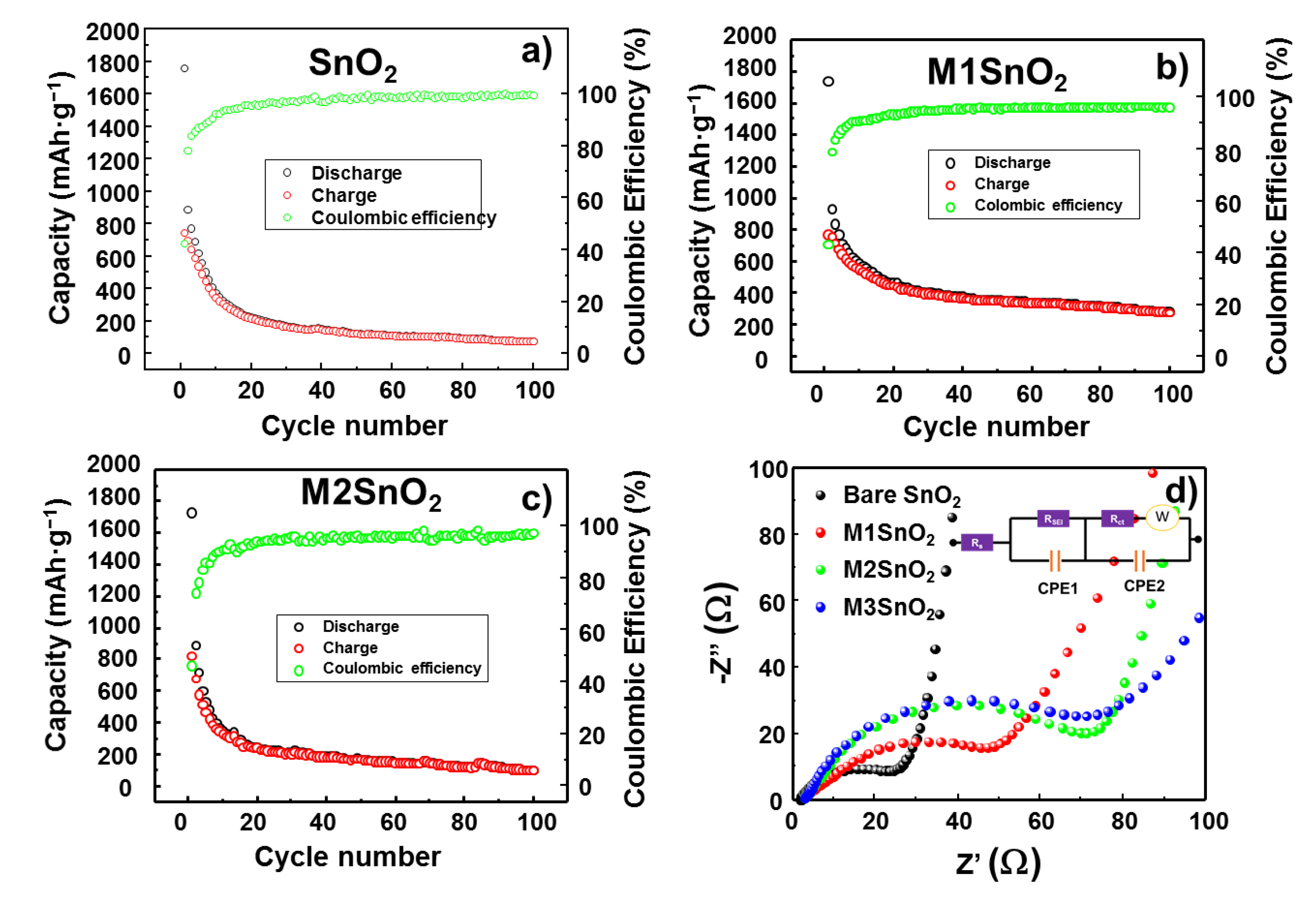
Figure 1. Illustration and photographs of self-assembled MoS2 nanosheet (NS) on Cu substrate.
Nanomaterials 10 02558 g001
Figure 2. Scanning electron microscope (SEM) images of (a,b) SnO2 nanoparticle (NP) powder, (c,d) single-layer MoS2 NS thin film on Cu electrode, and (e,f) M1SnO2 anode.
Nanomaterials 10 02558 g002
Figure 3. X-ray diffraction (XRD) patterns of (a) SnO2 NPs and M3SnO2 anode and (b) lithium-ion intercalated and exfoliated MoS2 nanosheet.
Nanomaterials 10 02558 g003
Figure 4. (a) Transmission electron microscope (TEM) image of SnO2 NP; energy-dispersive X-ray spectroscopy (EDS) mapping of the elements (b) O and (c) Sn; (d) high-resolution TEM (HRTEM) image of SnO2 NP with inset selected-area electron diffraction (SAED) pattern; (e) exfoliated MoS2 NS with inset SAED pattern.
Nanomaterials 10 02558 g004
Figure 5. Cyclic voltammetry (CV) profiles of (a) SnO2 NS and (bd) M1/M2/M3SnO2 anodes over three cycles.
Nanomaterials 10 02558 g005
Figure 6. Galvanostatic charge–discharge profiles of (a) SnO2 NS and (bd) M1/M2/M3SnO2 anodes for the initial three cycles.
Nanomaterials 10 02558 g006
Figure 7. Cyclic performances and Nyquist plots of (a) SnO2 NPs and (bd) M1/M2/M3SnO2 anodes.
Nanomaterials 10 02558 g007
Figure 8. Rate cycling performance of (a) bare SnO2 electrode and (b) M1SnO2 electrode at different current rates.
Nanomaterials 10 02558 g008
Figure 9. SEM images of (a,d) SnO2 electrode, (b,e) M1SnO2 electrode and (c,f) M3SnO2 electrode after 10 cycles at different magnifications.
Nanomaterials 10 02558 g009
Table 1. Resistance values extracted from the equivalent circuit of M1/M2/M3SnO2 anodes.
SampleRs (Ω)Rct (Ω)RSEI (Ω)
SnO2 NPs1.923.8500.2
M1SnO22.459.3182.7
M2SnO22.876.2284.8
M3SnO22.886.1305.1
Publisher’s Note: MDPI stays neutral with regard to jurisdictional claims in published maps and institutional affiliations.

