Opportunities for Persistent Luminescent Nanoparticles in Luminescence Imaging of Biological Systems and Photodynamic Therapy


 ,
,  and
and 
Abstract
1. Introduction
2. Luminescence Imaging
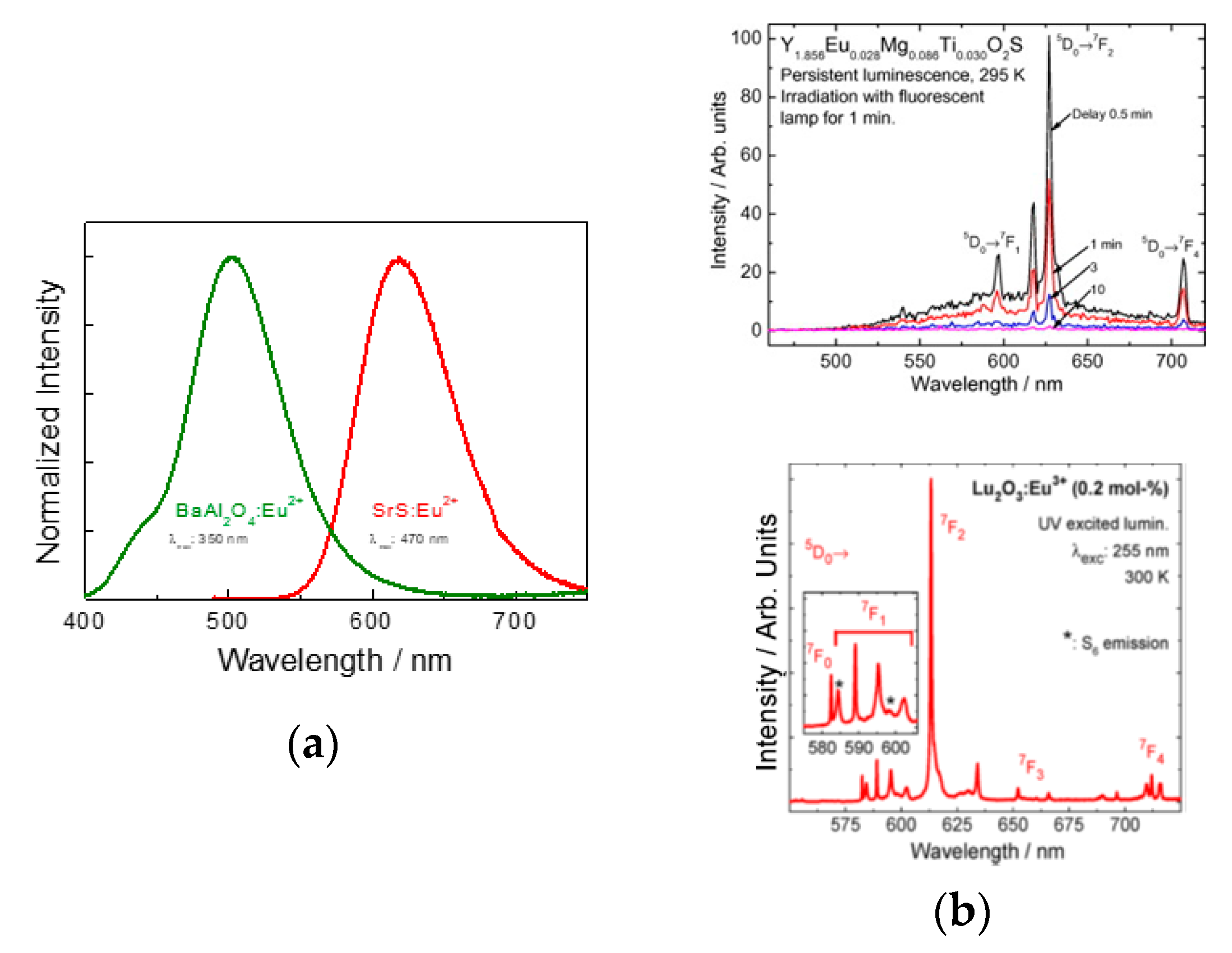
3. Persistent Luminescence
3.1. PeL Mechanism
3.2. Synthesis of PeL Nanomaterials
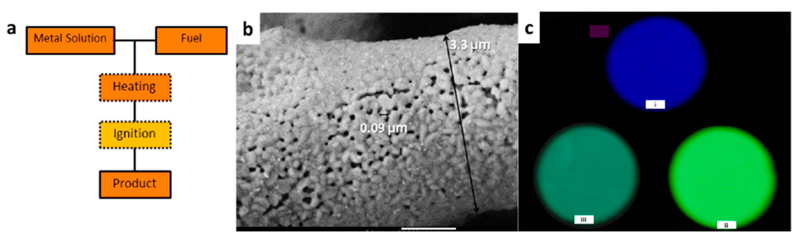
3.2.1. Combustion Synthesis
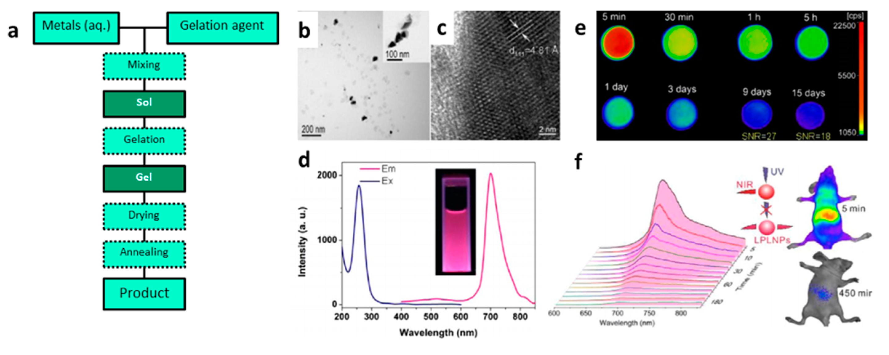
3.2.2. Sol–Gel Synthesis
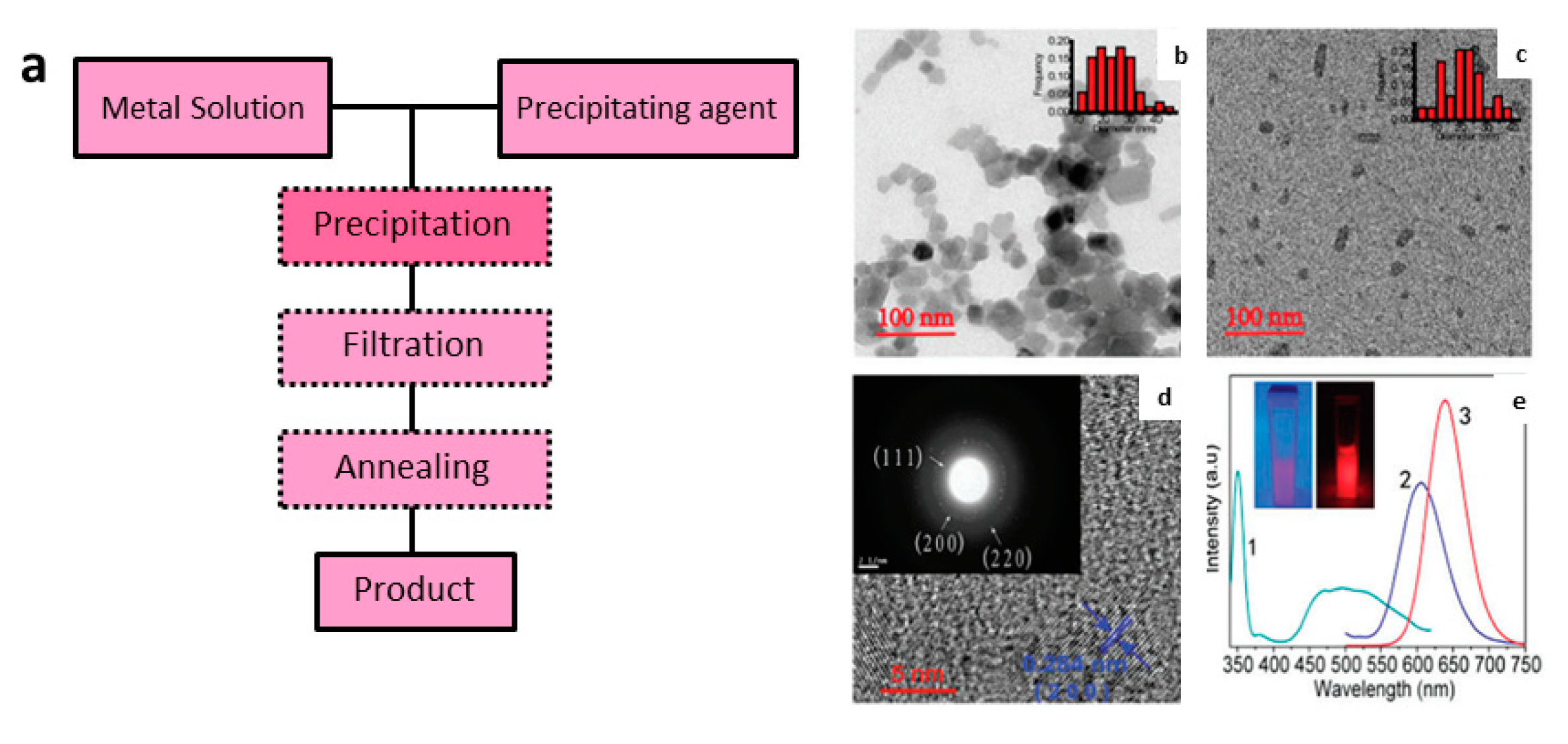
3.2.3. Co-Precipitation Synthesis
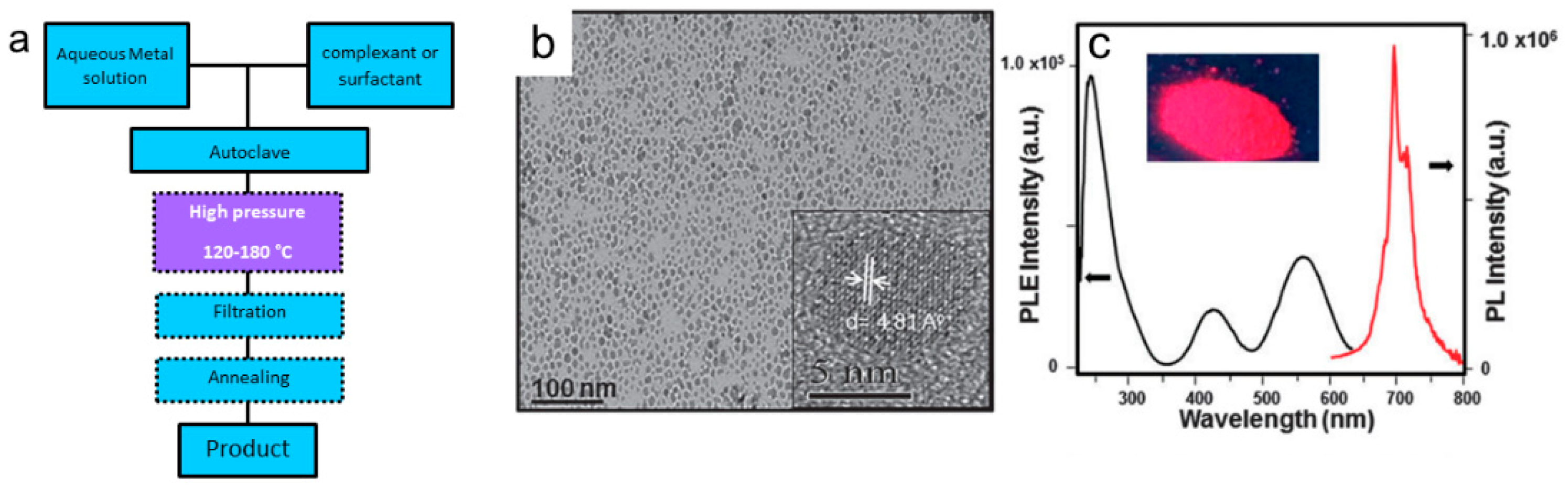
3.2.4. Hydrothermal Synthesis
4. Persistent Luminescence in Luminescence Imaging of Biological Systems
4.1. Excitation in the UV
4.2. Excitation in Visible
4.3. Excitation in the NIR
4.4. Excitation in the X-ray
4.5. Photodynamic Therapy Using Persistent Luminescence
5. Closing Remarks and Perspectives
Author Contributions
Funding
Conflicts of Interest
References
- Liu, L.; Zhang, H.; Song, D.; Wang, Z. An upconversion nanoparticle-based fluorescence resonance energy transfer system for effectively sensing caspase-3 activity. Analyst 2018, 143, 761–767. [Google Scholar] [CrossRef]
- Liang, T.; Li, Z.; Wang, P.; Zhao, F.; Liu, J.; Liu, Z. Breaking Through the Signal-to-Background Limit of Upconversion Nanoprobes Using a Target-Modulated Sensitizing Switch. J. Am. Chem. Soc. 2018, 140, 14696–14703. [Google Scholar] [CrossRef]
- Hao, C.; Wu, X.; Sun, M.; Zhang, H.; Yuan, A.; Xu, L.; Xu, C.; Kuang, H. Chiral Core-Shell Upconversion Nanoparticle@MOF Nanoassemblies for Quantification and Bioimaging of Reactive Oxygen Species In Vivo. J. Am. Chem. Soc. 2019, 141, 19373–19378. [Google Scholar] [CrossRef]
- Wang, H.; Zhao, W.; Liu, X.; Wang, S.; Wang, Y. BODIPY-Based Fluorescent Surfactant for Cell Membrane Imaging and Photodynamic Therapy. ACS Appl. Bio Mater. 2020, 3, 593–601. [Google Scholar] [CrossRef]
- Zhou, J.; Liu, Z.; Li, F. Upconversion nanophosphors for small-animal imaging. Chem. Soc. Rev. 2012, 41, 1323–1349. [Google Scholar] [CrossRef]
- Lo, K.K.-W. Molecular Design of Bioorthogonal Probes and Imaging Reagents Derived from Photofunctional Transition Metal Complexes. Acc. Chem. Res. 2020, 53, 32–44. [Google Scholar] [CrossRef] [PubMed]
- Lin, S.; Pan, H.; Li, L.; Liao, R.; Yu, S.; Zhao, Q.; Sun, H.; Huang, W. AIPE-active platinum(ii) complexes with tunable photophysical properties and their application in constructing thermosensitive probes used for intracellular temperature imaging. J. Mater. Chem. C 2019, 7, 7893–7899. [Google Scholar] [CrossRef]
- Chen, G.Y.; Qju, H.L.; Prasad, P.N.; Chen, X.Y. Upconversion Nanoparticles: Design, Nanochemistry, and Applications in Theranostics. Chem. Rev. 2014, 114, 5161–5214. [Google Scholar] [CrossRef] [PubMed]
- Wolfbeis, O.S. An overview of nanoparticles commonly used in fluorescent bioimaging. Chem. Soc. Rev. 2015, 44, 4743–4768. [Google Scholar] [CrossRef]
- Liu, G.; Jiang, F.; Chen, Y.; Yu, C.; Ding, B.; Shao, S.; Jia, M.; Ma, P.a.; Fu, Z.; Lin, J. Superior temperature sensing of small-sized upconversion nanocrystals for simultaneous bioimaging and enhanced synergetic therapy. Nanomed. Nanotechnol. Biol. Med. 2019, 24, 102135. [Google Scholar] [CrossRef]
- Gargas, D.J.; Chan, E.M.; Ostrowski, A.D.; Aloni, S.; Altoe, M.V.P.; Barnard, E.S.; Sanii, B.; Urban, J.J.; Milliron, D.J.; Cohen, B.E.; et al. Engineering bright sub-10-nm upconverting nanocrystals for single-molecule imaging. Nat. Nanotechnol. 2014, 9, 300–305. [Google Scholar] [CrossRef]
- Zhao, M.; Wang, R.; Li, B.; Fan, Y.; Wu, Y.; Zhu, X.; Zhang, F. Precise In Vivo Inflammation Imaging Using In Situ Responsive Cross-linking of Glutathione-Modified Ultra-Small NIR-II Lanthanide Nanoparticles. Angew. Chem. (Int. Ed. Engl.) 2019, 58, 2050–2054. [Google Scholar] [CrossRef] [PubMed]
- Chen, C.; Tian, R.; Zeng, Y.; Chu, C.; Liu, G. Activatable Fluorescence Probes for “Turn-On” and Ratiometric Biosensing and Bioimaging: From NIR-I to NIR-II. Bioconjugate Chem. 2020, 31, 276–292. [Google Scholar] [CrossRef]
- Dobrucki, J.W.; Kubitscheck, U. Fluorescence Microscopy. In Fluorescence Microscopy: From Principles to Biological Applications, 2nd ed.; Kubitscheck, U., Ed.; Wiley: Berlin, Germany, 2017; pp. 85–132. [Google Scholar]
- Monteiro, J.; Machado, D.; de Hollanda, L.M.; Lancellotti, M.; Sigoli, F.A.; de Bettencourt-Dias, A. Selective cytotoxicity and luminescence imaging of cancer cells with a dipicolinato-based Eu-III complex. Chem. Commun. 2017, 53, 11818–11821. [Google Scholar] [CrossRef] [PubMed]
- Chauvin, A.S.; Comby, S.; Song, B.; Vandevyver, C.D.; Bünzli, J.-C.G. A versatile ditopic ligand system for sensitizing the luminescence of bimetallic lanthanide bio-imaging probes. Chem. Eur. J. 2008, 14, 1726–1739. [Google Scholar] [CrossRef] [PubMed]
- Fernandez-Moreira, V.; Song, B.; Sivagnanam, V.; Chauvin, A.S.; Vandevyver, C.D.; Gijs, M.; Hemmila, I.; Lehr, H.A.; Bünzli, J.-C.G. Bioconjugated lanthanide luminescent helicates as multilabels for lab-on-a-chip detection of cancer biomarkers. Analyst 2010, 135, 42–52. [Google Scholar] [CrossRef]
- Surender, E.M.; Comby, S.; Cavanagh, B.L.; Brennan, O.; Lee, T.C.; Gunnlaugsson, T. Two-Photon Luminescent Bone Imaging Using Europium Nanoagents. Chem 2016, 1, 438–455. [Google Scholar] [CrossRef]
- Addisu, K.D.; Hsu, W.-H.; Hailemeskel, B.Z.; Andrgie, A.T.; Chou, H.-Y.; Yuh, C.-H.; Lai, J.-Y.; Tsai, H.-C. Mixed Lanthanide Oxide Nanoparticles Coated with Alginate-Polydopamine as Multifunctional Nanovehicles for Dual Modality: Targeted Imaging and Chemotherapy. ACS Biomater. Sci. Eng. 2019, 5, 5453–5469. [Google Scholar] [CrossRef]
- Chen, Z.; Chen, H.; Hu, H.; Yu, M.; Li, F.; Zhang, Q.; Zhou, Z.; Yi, T.; Huang, C. Versatile synthesis strategy for carboxylic acid-functionalized upconverting nanophosphors as biological labels. J. Am. Chem. Soc. 2008, 130, 3023–3029. [Google Scholar] [CrossRef]
- Song, X.; Zhang, J.; Yue, Z.; Wang, Z.; Liu, Z.; Zhang, S. Dual-Activator Codoped Upconversion Nanoprobe with Core-Multishell Structure for in Vitro and in Vivo Detection of Hydroxyl Radical. Anal. Chem. 2017, 89, 11021–11026. [Google Scholar] [CrossRef]
- Zhang, R.; Liang, L.; Meng, Q.; Zhao, J.; Ta, H.T.; Li, L.; Zhang, Z.; Sultanbawa, Y.; Xu, Z.P. Responsive Upconversion Nanoprobe for Background-Free Hypochlorous Acid Detection and Bioimaging. Small (Weinh. Der Bergstr. Ger.) 2019, 15, e1803712. [Google Scholar] [CrossRef] [PubMed]
- Wang, F.; Qu, X.; Liu, D.; Ding, C.; Zhang, C.; Xian, Y. Upconversion nanoparticles-MoS2 nanoassembly as a fluorescent turn-on probe for bioimaging of reactive oxygen species in living cells and zebrafish. Sens. Actuators B Chem. 2018, 274, 180–187. [Google Scholar] [CrossRef]
- Yang, L.; Zhang, K.; Bi, S.; Zhu, J.-J. Dual-Acceptor-Based Upconversion Luminescence Nanosensor with Enhanced Quenching Efficiency for in Situ Imaging and Quantification of MicroRNA in Living Cells. ACS Appl. Mater. Interfaces 2019, 11, 38459–38466. [Google Scholar] [CrossRef] [PubMed]
- Song, X.; Yue, Z.; Zhang, J.; Jiang, Y.; Wang, Z.; Zhang, S. Multicolor Upconversion Nanoprobes Based on a Dual Luminescence Resonance Energy Transfer Assay for Simultaneous Detection and Bioimaging of Ca2+ i and pHi in Living Cells. Chemistry 2018, 24, 6458–6463. [Google Scholar] [CrossRef] [PubMed]
- Shi, Y.; Liu, Q.; Yuan, W.; Xue, M.; Feng, W.; Li, F. Dye-Assembled Upconversion Nanocomposite for Luminescence Ratiometric in Vivo Bioimaging of Copper Ions. ACS Appl. Mater. Interfaces 2019, 11, 430–436. [Google Scholar] [CrossRef]
- Li, Z.; Liu, H.; Li, H.; Tsou, Y.-H.; Gao, Y.; Xu, X.; Du, W.; Wei, L.; Yu, M. Lysosome-targeting NIR ratiometric luminecent upcoversion nanoprobe toward arginine. Sens. Actuators B Chem. 2019, 280, 94–101. [Google Scholar] [CrossRef]
- Wang, N.; Yu, X.; Zhang, K.; Mirkin, C.A.; Li, J. Upconversion Nanoprobes for the Ratiometric Luminescent Sensing of Nitric Oxide. J. Am. Chem. Soc. 2017, 139, 12354–12357. [Google Scholar] [CrossRef]
- Tsukube, H.; Shinoda, S. Lanthanide complexes in molecular recognition and chirality sensing of biological substrates. Chem. Rev. 2002, 102, 2389–2403. [Google Scholar] [CrossRef]
- Pandya, S.; Yu, J.; Parker, D. Engineering emissive europium and terbium complexes for molecular imaging and sensing. Dalton Trans. (Camb. Engl. 2003) 2006, 2757–2766. [Google Scholar] [CrossRef]
- Harbuzaru, B.V.; Corma, A.; Rey, F.; Jorda, J.L.; Ananias, D.; Carlos, L.D.; Rocha, J. A miniaturized linear pH sensor based on a highly photoluminescent self-assembled europium(III) metal-organic framework. Angew. Chem. (Int. Ed. Engl.) 2009, 48, 6476–6479. [Google Scholar] [CrossRef]
- Gunnlaugsson, T.; Leonard, J.P. Responsive lanthanide luminescent cyclen complexes: From switching/sensing to supramolecular architectures. Chem. Commun. (Camb. Engl.) 2005, 3114–3131. [Google Scholar] [CrossRef] [PubMed]
- Tan, H.; Liu, B.; Chen, Y. Lanthanide coordination polymer nanoparticles for sensing of mercury(II) by photoinduced electron transfer. ACS Nano 2012, 6, 10505–10511. [Google Scholar] [CrossRef] [PubMed]
- Khullar, S.; Singh, S.; Das, P.; Mandal, S.K. Luminescent Lanthanide-Based Probes for the Detection of Nitroaromatic Compounds in Water. ACS Omega 2019, 4, 5283–5292. [Google Scholar] [CrossRef] [PubMed]
- Wang, H.-F.; Ma, X.-F.; Zhu, Z.-H.; Zou, H.-H.; Liang, F.-P. Regulation of the Metal Center and Coordinating Anion of Mononuclear Ln(III) Complexes to Promote an Efficient Luminescence Response to Various Organic Solvents. Langmuir ACS J. Surf. Colloids 2020, 36, 1409–1417. [Google Scholar] [CrossRef]
- Hewitt, S.H.; Macey, G.; Mailhot, R.; Elsegood, M.R.J.; Duarte, F.; Kenwright, A.M.; Butler, S.J. Tuning the anion binding properties of lanthanide receptors to discriminate nucleoside phosphates in a sensing array. Chem. Sci. 2020, 11, 3619–3628. [Google Scholar] [CrossRef]
- Yang, Z.; Loh, K.Y.; Chu, Y.-T.; Feng, R.; Satyavolu, N.S.R.; Xiong, M.; Huynh, S.M.N.; Hwang, K.; Li, L.; Xing, H.; et al. Optical Control of Metal Ion Probes in Cells and Zebrafish Using Highly Selective DNAzymes Conjugated to Upconversion Nanoparticles. J. Am. Chem. Soc. 2018, 140, 17656–17665. [Google Scholar] [CrossRef]
- Li, X.; Zhao, H.; Ji, Y.; Yin, C.; Li, J.; Yang, Z.; Tang, Y.; Zhang, Q.; Fan, Q.; Huang, W. Lysosome-Assisted Mitochondrial Targeting Nanoprobe Based on Dye-Modified Upconversion Nanophosphors for Ratiometric Imaging of Mitochondrial Hydrogen Sulfide. ACS Appl. Mater. Interfaces 2018, 10, 39544–39556. [Google Scholar] [CrossRef]
- Tang, Z.; Song, B.; Zhang, W.; Guo, L.; Yuan, J. Precise Monitoring of Drug-Induced Kidney Injury Using an Endoplasmic Reticulum-Targetable Ratiometric Time-Gated Luminescence Probe for Superoxide Anions. Anal. Chem. 2019, 91, 14019–14028. [Google Scholar] [CrossRef]
- Ma, H.; Song, B.; Wang, Y.; Liu, C.; Wang, X.; Yuan, J. Development of organelle-targetable europium complex probes for time-gated luminescence imaging of hypochlorous acid in live cells and animals. Dyes Pigm. 2017, 140, 407–416. [Google Scholar] [CrossRef]
- Tang, Z.; Song, B.; Ma, H.; Luo, T.; Guo, L.; Yuan, J. Mitochondria Targetable Ratiometric Time-Gated Luminescence Probe for Carbon Monoxide Based on Lanthanide Complexes. Anal. Chem. 2019, 91, 2939–2946. [Google Scholar] [CrossRef]
- Liu, Y.H.; Wang, Y.H.; Jiang, K.; Sun, S.; Qian, S.H.; Wu, Q.P.; Lin, H. A persistent luminescence-based label-free probe for the ultrasensitive detection of hemoglobin in human serum. Talanta 2020, 206. [Google Scholar] [CrossRef] [PubMed]
- Wu, S.; Li, Y.; Zhang, R.; Fan, K.; Ding, W.; Xu, L.; Zhang, L. Persistent luminescence-polypyrrole nanocomposite for dual-modal imaging and photothermal therapy of mammary cancer. Talanta 2021, 221, 121435. [Google Scholar] [CrossRef]
- Ding, S.; Guo, H.; Feng, P.; Ye, Q.; Wang, Y. A New Near-Infrared Long Persistent Luminescence Material with Its Outstanding Persistent Luminescence Performance and Promising Multifunctional Application Prospects. Adv. Opt. Mater. 2020, 8, 2000097. [Google Scholar] [CrossRef]
- Shi, L.X.; Shao, J.J.; Jing, X.H.; Zheng, W.W.; Liu, H.; Zhao, Y. Autoluminescence-Free Dual Tumor Marker Biosensing by Persistent Luminescence Nanostructures. ACS Sustain. Chem. Eng. 2020, 8, 686–694. [Google Scholar] [CrossRef]
- Wang, Z.H.; Liu, J.M.; Zhao, N.; Li, C.Y.; Lv, S.W.; Hu, Y.Z.; Lv, H.; Wang, D.; Wang, S. Cancer Cell Macrophage Membrane Camouflaged Persistent Luminescent Nanoparticles for Imaging-Guided Photothermal Therapy of Colorectal Cancer. ACS Appl. Nano Mater. 2020, 3, 7105–7118. [Google Scholar] [CrossRef]
- Pan, Z.W.; Lu, Y.Y.; Liu, F. Sunlight-activated long-persistent luminescence in the near-infrared from Cr3+-doped zinc gallogermanates. Nat. Mater. 2012, 11, 58–63. [Google Scholar] [CrossRef] [PubMed]
- Maldiney, T.; Bessière, A.; Seguin, J.; Teston, E.; Sharma, S.K.; Viana, B.; Bos, A.J.J.; Dorenbos, P.; Bessodes, M.; Gourier, D.; et al. The in vivo activation of persistent nanophosphors for optical imaging of vascularization, tumours and grafted cells. Nat. Mater. 2014, 13, 418–426. [Google Scholar] [CrossRef]
- Van den Eeckhout, K.; Smet, P.F.; Poelman, D. Persistent Luminescence in Eu2+-Doped Compounds: A Review. Materials 2010, 3, 2536. [Google Scholar] [CrossRef]
- Lin, Q.S.; Li, Z.H.; Ji, C.H.; Yuan, Q. Electronic structure engineering and biomedical applications of low energy-excited persistent luminescence nanoparticles. Nanoscale Adv. 2020, 2, 1380–1394. [Google Scholar] [CrossRef]
- Liu, J.H.; Lecuyer, T.; Seguin, J.; Mignet, N.; Scherman, D.; Viana, B.; Richard, C. Imaging and therapeutic applications of persistent luminescence nanomaterials. Adv. Drug Deliv. Rev. 2019, 138, 193–210. [Google Scholar] [CrossRef]
- Sun, S.K.; Wang, H.F.; Yan, X.P. Engineering Persistent Luminescence Nanoparticles for Biological Applications: From Biosensing/Bioimaging to Theranostics. Acc. Chem. Res. 2018, 51, 1131–1143. [Google Scholar] [CrossRef] [PubMed]
- Liang, L.; Chen, N.; Jia, Y.Y.; Ma, Q.Q.; Wang, J.; Yuan, Q.; Tan, W.H. Recent progress in engineering near-infrared persistent luminescence nanoprobes for time-resolved biosensing/bioimaging. Nano Res. 2019, 12, 1279–1292. [Google Scholar] [CrossRef]
- Tan, H.X.; Wang, T.Y.; Shao, Y.R.; Yu, C.Y.; Hu, L.D. Crucial Breakthrough of Functional Persistent Luminescence Materials for Biomedical and Information Technological Applications. Front. Chem. 2019, 7, 387. [Google Scholar] [CrossRef] [PubMed]
- Li, Y.; Li, F.; Huang, Y.; Wu, H.; Wang, J.; Yang, J.; Xiao, Q.; Lin, H. Fe3+-codoped ultra-small NaGdF4:Nd3+ nanophosphors: Enhanced near-infrared luminescence, reduced particle size and bioimaging applications. Rsc Adv. 2019, 9, 18070–18075. [Google Scholar] [CrossRef]
- Song, X.; Li, S.; Guo, H.; You, W.; Shang, X.; Li, R.; Tu, D.; Zheng, W.; Chen, Z.; Yang, H.; et al. Graphene-Oxide-Modified Lanthanide Nanoprobes for Tumor-Targeted Visible/NIR-II Luminescence Imaging. Angew. Chem. (Int. Ed. Engl.) 2019, 58, 18981–18986. [Google Scholar] [CrossRef]
- Cao, C.; Liu, Q.; Shi, M.; Feng, W.; Li, F. Lanthanide-Doped Nanoparticles with Upconversion and Downshifting Near-Infrared Luminescence for Bioimaging. Inorg. Chem. 2019, 58, 9351–9357. [Google Scholar] [CrossRef]
- Wang, X.; Shi, J.; Li, P.; Zheng, S.; Sun, X.; Zhang, H. LuPO4:Nd3+ nanophosphors for dual-mode deep tissue NIR-II luminescence/CT imaging. J. Lumin. 2019, 209, 420–426. [Google Scholar] [CrossRef]
- Feng, Y.; Xiao, Q.; Zhang, Y.; Li, F.; Li, Y.; Li, C.; Wang, Q.; Shi, L.; Lin, H. Neodymium-doped NaHoF4 nanoparticles as near-infrared luminescent/T2-weighted MR dual-modal imaging agents in vivo. J. Mater. Chem. B 2017, 5, 504–510. [Google Scholar] [CrossRef]
- Wang, X.; Li, H.; Li, F.; Han, X.; Chen, G. Prussian blue-coated lanthanide-doped core/shell/shell nanocrystals for NIR-II image-guided photothermal therapy. Nanoscale 2019, 11, 22079–22088. [Google Scholar] [CrossRef]
- Barolet, D. Light-emitting diodes (LEDs) in dermatology. Semin. Cutan. Med. Surg. 2008, 27, 227–238. [Google Scholar] [CrossRef]
- Hao, S.; Chen, G.; Yang, C.; Shao, W.; Wei, W.; Liu, Y.; Prasad, P.N. Nd3+-Sensitized multicolor upconversion luminescence from a sandwiched core/shell/shell nanostructure. Nanoscale 2017, 9, 10633–10638. [Google Scholar] [CrossRef] [PubMed]
- Ai, F.; Ju, Q.; Zhang, X.; Chen, X.; Wang, F.; Zhu, G. A core-shell-shell nanoplatform upconverting near-infrared light at 808 nm for luminescence imaging and photodynamic therapy of cancer. Sci. Rep. 2015, 5, 10785. [Google Scholar] [CrossRef] [PubMed]
- Jaque, D.; Richard, C.; Viana, B.; Soga, K.; Liu, X.G.; Sole, J.G. Inorganic nanoparticles for optical bioimaging. Adv. Opt. Photonics 2016, 8, 1–103. [Google Scholar] [CrossRef]
- Smith, A.M.; Mancini, M.C.; Nie, S. BIOIMAGING Second window for in vivo imaging. Nat. Nanotechnol. 2009, 4, 710–711. [Google Scholar] [CrossRef]
- Li, Y.; Li, X.; Xue, Z.; Jiang, M.; Zeng, S.; Hao, J. Second near-infrared emissive lanthanide complex for fast renal-clearable in vivo optical bioimaging and tiny tumor detection. Biomaterials 2018, 169, 35–44. [Google Scholar] [CrossRef]
- Yang, Y.; Wang, P.; Lu, L.; Fan, Y.; Sun, C.; Fan, L.; Xu, C.; El-Toni, A.M.; Alhoshan, M.; Zhang, F. Small-Molecule Lanthanide Complexes Probe for Second Near-Infrared Window Bioimaging. Anal. Chem. 2018, 90, 7946–7952. [Google Scholar] [CrossRef]
- Ning, Y.; Cheng, S.; Wang, J.-X.; Liu, Y.-W.; Feng, W.; Li, F.; Zhang, J.-L. Fluorescence lifetime imaging of upper gastrointestinal pH in vivo with a lanthanide based near-infrared τ probe. Chem. Sci. 2019, 10, 4227–4235. [Google Scholar] [CrossRef]
- Ren, T.; Xu, W.; Zhang, Q.; Zhang, X.; Wen, S.; Yi, H.; Yuan, L.; Zhang, X. Harvesting Hydrogen Bond Network: Enhance the Anti-Solvatochromic Two-Photon Fluorescence for Cirrhosis Imaging. Angew. Chem. Int. Ed. 2018, 57, 7473–7477. [Google Scholar] [CrossRef]
- Agrawalla, B.K.; Lee, H.W.; Phue, W.H.; Raju, A.; Kim, J.J.; Kim, H.M.; Kang, N.Y.; Chang, Y.T. Two-Photon Dye Cocktail for Dual-Color 3D Imaging of Pancreatic Beta and Alpha Cells in Live Islets. J. Am. Chem. Soc. 2017, 139, 3480–3487. [Google Scholar] [CrossRef]
- Agrawalla, B.K.; Chandran, Y.; Phue, W.H.; Lee, S.C.; Jeong, Y.M.; Wan, S.Y.D.; Kang, N.Y.; Chang, Y.T. Glucagon-Secreting Alpha Cell Selective Two-Photon Fluorescent Probe TP-alpha: For Live Pancreatic Islet Imaging. J. Am. Chem. Soc. 2015, 137, 5355–5362. [Google Scholar] [CrossRef]
- Kumari, P.; Verma, S.K.; Mobin, S.M. Water soluble two-photon fluorescent organic probes for long-term imaging of lysosomes in live cells and tumor spheroids. Chem. Commun. 2018, 54, 539–542. [Google Scholar] [CrossRef] [PubMed]
- Hirsch, L.R.; Stafford, R.J.; Bankson, J.A.; Sershen, S.R.; Rivera, B.; Price, R.E.; Hazle, J.D.; Halas, N.J.; West, J.L. Nanoshell-mediated near-infrared thermal therapy of tumors under magnetic resonance guidance. Proc. Natl. Acad. Sci. USA 2003, 100, 13549–13554. [Google Scholar] [CrossRef] [PubMed]
- Robinson, J.T.; Tabakman, S.M.; Liang, Y.Y.; Wang, H.L.; Casalongue, H.S.; Vinh, D.; Dai, H.J. Ultrasmall Reduced Graphene Oxide with High Near-Infrared Absorbance for Photothermal Therapy. J. Am. Chem. Soc. 2011, 133, 6825–6831. [Google Scholar] [CrossRef]
- Jaque, D.; Maestro, L.M.; del Rosal, B.; Haro-Gonzalez, P.; Benayas, A.; Plaza, J.L.; Rodriguez, E.M.; Sole, J.G. Nanoparticles for photothermal therapies. Nanoscale 2014, 6, 9494–9530. [Google Scholar] [CrossRef] [PubMed]
- Zheng, B.-D.; He, Q.-X.; Li, X.; Yoon, J.; Huang, J.-D. Phthalocyanines as contrast agents for photothermal therapy. Coord. Chem. Rev. 2021, 426, 213548. [Google Scholar] [CrossRef]
- Zeng, X.M.; Yan, S.Q.; Di, C.; Lei, M.C.; Chen, P.; Du, W.; Jin, Y.; Liu, B.F. “All-in-One” Silver Nanoprism Platform for Targeted Tumor Theranostics. ACS Appl. Mater. Interfaces 2020, 12, 11329–11340. [Google Scholar] [CrossRef]
- Zhang, J.J.; Ning, L.L.; Huang, J.G.; Zhang, C.; Pu, K.Y. Activatable molecular agents for cancer theranostics. Chem. Sci. 2020, 11, 618–630. [Google Scholar] [CrossRef]
- Castano, A.P.; Mroz, P.; Hamblin, M.R. Photodynamic therapy and anti-tumour immunity. Nat. Rev. Cancer 2006, 6, 535–545. [Google Scholar] [CrossRef]
- Cheng, P.H.; Pu, K.Y. Activatable Phototheranostic Materials for Imaging-Guided Cancer Therapy. ACS Appl. Mater. Interfaces 2020, 12, 5286–5299. [Google Scholar] [CrossRef]
- Celli, J.P.; Spring, B.Q.; Rizvi, I.; Evans, C.L.; Samkoe, K.S.; Verma, S.; Pogue, B.W.; Hasan, T. Imaging and Photodynamic Therapy: Mechanisms, Monitoring, and Optimization. Chem. Rev. 2010, 110, 2795–2838. [Google Scholar] [CrossRef]
- Lifshits, L.; Roque Iii, J.A.; Konda, P.; Monro, S.; Cole, H.D.; von Dohlen, D.; Kim, S.; Deep, G.; Thummel, R.P.; Cameron, C.G.; et al. Near-infrared Absorbing Ru(II) Complexes Act as Immunoprotective Photodynamic Therapy (PDT) Agents Against Aggressive Melanoma. Chem. Sci. 2020. [Google Scholar] [CrossRef]
- Johnson, K.R.; Lombardi, V.C.; de Bettencourt-Dias, A. Photocytotoxicity of Oligothienyl-Functionalized Chelates That Sensitize LnIII Luminescence and Generate 1O2. Chem. A Eur. J. 2020, n/a. [Google Scholar] [CrossRef]
- Herzog, R.W.; Frederickson, R.M. Special Issue Features State-of-the-Art in Clinical Gene Therapy. Mol. Ther. 2020, 28, 1933. [Google Scholar] [CrossRef]
- Hu, L.; Fu, X.; Kong, G.; Yin, Y.; Meng, H.; Ke, G.; Zhang, X. DNAzyme-Gold Nanoparticle-based Probes for Biosensing and Bioimaging. J. Mater. Chem. B 2020. [Google Scholar] [CrossRef]
- Li, L.; Tian, H.; He, J.; Zhang, M.; Li, Z.-G.; Ni, P. Fabrication of aminated poly(glycidyl methacrylate)s-based polymers for co-delivery of anticancer drug and p53 gene. J. Mater. Chem. B 2020. [Google Scholar] [CrossRef]
- Li, X.; Lee, D.; Huang, J.-D.; Yoon, J. Phthalocyanine-Assembled Nanodots as Photosensitizers for Highly Efficient Type I Photoreactions in Photodynamic Therapy. Angew. Chem. (Int. Ed. Engl.) 2018, 57, 9885–9890. [Google Scholar] [CrossRef]
- Fujishiro, R.; Sonoyama, H.; Ide, Y.; Fujimura, T.; Sasai, R.; Nagai, A.; Mori, S.; Kaufman, N.E.M.; Zhou, Z.; Vicente, M.G.H.; et al. Synthesis, photodynamic activities, and cytotoxicity of new water-soluble cationic gallium(III) and zinc(II) phthalocyanines. J. Inorg. Biochem. 2019, 192, 7–16. [Google Scholar] [CrossRef]
- Toubia, I.; Nguyen, C.; Diring, S.; Ali, L.M.A.; Larue, L.; Aoun, R.; Frochot, C.; Gary-Bobo, M.; Kobeissi, M.; Odobel, F. Synthesis and Anticancer Activity of Gold Porphyrin Linked to Malonate Diamine Platinum Complexes. Inorg. Chem. 2019, 58, 12395–12406. [Google Scholar] [CrossRef]
- Wu, S.; Li, Y.; Ding, W.; Xu, L.; Ma, Y.; Zhang, L. Recent Advances of Persistent Luminescence Nanoparticles in Bioapplications. Nano-Micro Lett. 2020, 12, 70. [Google Scholar] [CrossRef]
- Xu, J.; Tanabe, S. Persistent luminescence instead of phosphorescence: History, mechanism, and perspective. J. Lumin. 2019, 205, 581–620. [Google Scholar] [CrossRef]
- Van den Eeckhout, K.; Poelman, D.; Smet, P.F. Persistent Luminescence in Non-Eu2+-Doped Compounds: A Review. Materials 2013, 6, 2789–2818. [Google Scholar] [CrossRef] [PubMed]
- Brito, H.F.; Holsa, J.; Laamanen, T.; Lastusaari, M.; Malkamaki, M.; Rodrigues, L.C.V. Persistent luminescence mechanisms: Human imagination at work. Opt. Mater. Express 2012, 2, 371–381. [Google Scholar] [CrossRef]
- Monteiro, J.H.S.K. Recent Advances in Luminescence Imaging of Biological Systems Using Lanthanide(III) Luminescent Complexes. Molecules 2020, 25, 2089. [Google Scholar] [CrossRef] [PubMed]
- Day, A.H.; Übler, M.H.; Best, H.L.; Lloyd-Evans, E.; Mart, R.J.; Fallis, I.A.; Allemann, R.K.; Al-Wattar, E.A.H.; Keymer, N.I.; Buurma, N.J.; et al. Targeted cell imaging properties of a deep red luminescent iridium(iii) complex conjugated with a c-Myc signal peptide. Chem. Sci. 2020, 11, 1599–1606. [Google Scholar] [CrossRef]
- Ahmed, M.U.; Velkov, T.; Zhou, Q.T.; Fulcher, A.J.; Callaghan, J.; Zhou, F.; Chan, K.; Azad, M.A.K.; Li, J. Intracellular localization of polymyxins in human alveolar epithelial cells. J. Antimicrob. Chemother. 2018, 74, 48–57. [Google Scholar] [CrossRef]
- Zheng, Q.; Cheng, W.; Zhang, X.; Shao, R.; Li, Z. A pH-Induced Reversible Assembly System with Resveratrol-Controllable Loading and Release for Enhanced Tumor-Targeting Chemotherapy. Nanoscale Res. Lett. 2019, 14, 305. [Google Scholar] [CrossRef]
- Yang, T.; Xu, L.; Liu, S.; Shen, Y.; Huang, L.; Zhang, L.; Ding, S.; Cheng, W. Amplified fluorescence imaging of HER2 dimerization on cancer cells by using a co-localization triggered DNA nanoassembly. Microchim. Acta 2019, 186, 439. [Google Scholar] [CrossRef] [PubMed]
- Li, J.; Wei, Y.-J.; Yang, X.-L.; Wu, W.-X.; Zhang, M.-Q.; Li, M.-Y.; Hu, Z.-E.; Liu, Y.-H.; Wang, N.; Yu, X.-Q. Rational Construction of a Mitochondrial Targeting, Fluorescent Self-Reporting Drug-Delivery Platform for Combined Enhancement of Endogenous ROS Responsiveness. ACS Appl. Mater. Interfaces 2020, 12, 32432–32445. [Google Scholar] [CrossRef] [PubMed]
- Xu, W.; Teoh, C.L.; Peng, J.; Su, D.; Yuan, L.; Chang, Y.-T. A mitochondria-targeted ratiometric fluorescent probe to monitor endogenously generated sulfur dioxide derivatives in living cells. Biomaterials 2015, 56, 1–9. [Google Scholar] [CrossRef]
- Xu, Z.; Zhang, M.-X.; Xu, Y.; Liu, S.H.; Zeng, L.; Chen, H.; Yin, J. The visualization of lysosomal and mitochondrial glutathione via near-infrared fluorophore and in vivo imaging application. Sens. Actuators B Chem. 2019, 290, 676–683. [Google Scholar] [CrossRef]
- Mayer, M.; Fey, K.; Heinze, E.; Wick, C.R.; Abboud, M.I.; Yeh, T.-L.; Tumber, A.; Orth, N.; Schley, G.; Buchholz, B.; et al. A Fluorescent Benzo[g]isoquinoline-Based HIF Prolyl Hydroxylase Inhibitor for Cellular Imaging. ChemMedChem 2019, 14, 94–99. [Google Scholar] [CrossRef] [PubMed]
- Wang, Y.-S.; Tzeng, H.-T.; Tsai, C.-H.; Cheng, H.-C.; Lai, W.-W.; Liu, H.-S.; Wang, Y.-C. VAMP8, a vesicle-SNARE required for RAB37-mediated exocytosis, possesses a tumor metastasis suppressor function. Cancer Lett. 2018, 437, 79–88. [Google Scholar] [CrossRef] [PubMed]
- Soboleva, T.; Esquer, H.J.; Anderson, S.N.; Berreau, L.M.; Benninghoff, A.D. Mitochondrial-Localized Versus Cytosolic Intracellular CO-Releasing Organic PhotoCORMs: Evaluation of CO Effects Using Bioenergetics. ACS Chem. Biol. 2018, 13, 2220–2228. [Google Scholar] [CrossRef]
- Xu, J.; Pan, J.; Jiang, X.; Qin, C.; Zeng, L.; Zhang, H.; Zhang, J.F. A mitochondria-targeted ratiometric fluorescent probe for rapid, sensitive and specific detection of biological SO2 derivatives in living cells. Biosens. Bioelectron. 2016, 77, 725–732. [Google Scholar] [CrossRef]
- Huth, U.S.; Schubert, R.; Peschka-Süss, R. Investigating the uptake and intracellular fate of pH-sensitive liposomes by flow cytometry and spectral bio-imaging. J. Control. Release 2006, 110, 490–504. [Google Scholar] [CrossRef]
- Sun, J.; Song, B.; Ye, Z.; Yuan, J. Mitochondria Targetable Time-Gated Luminescence Probe for Singlet Oxygen Based on a beta-Diketonate-Europium Complex. Inorg. Chem. 2015, 54, 11660–11668. [Google Scholar] [CrossRef]
- Suzuki, T.; Matsuzaki, T.; Hagiwara, H.; Aoki, T.; Takata, K. Recent Advances in Fluorescent Labeling Techniques for Fluorescence Microscopy. Acta Histochem. Et Cytochem. 2007, 40, 131–137. [Google Scholar] [CrossRef]
- Wang, L.; Wang, J.; Xia, S.; Wang, X.; Yu, Y.; Zhou, H.; Liu, H. A FRET-based near-infrared ratiometric fluorescent probe for detection of mitochondria biothiol. Talanta 2020, 219, 121296. [Google Scholar] [CrossRef]
- Yuan, L.; Lin, W.Y.; Zheng, K.B.; He, L.W.; Huang, W.M. Far-red to near infrared analyte-responsive fluorescent probes based on organic fluorophore platforms for fluorescence imaging. Chem. Soc. Rev. 2013, 42, 622–661. [Google Scholar] [CrossRef] [PubMed]
- Hamon, N.; Roux, A.; Beyler, M.; Mulatier, J.-C.; Andraud, C.; Nguyen, C.; Maynadier, M.; Bettache, N.; Duperray, A.; Grichine, A.; et al. Pyclen-Based Ln(III) Complexes as Highly Luminescent Bioprobes for In Vitro and In Vivo One- and Two-Photon Bioimaging Applications. J. Am. Chem. Soc. 2020, 142, 10184–10197. [Google Scholar] [CrossRef]
- Hamon, N.; Galland, M.; Le Fur, M.; Roux, A.; Duperray, A.; Grichine, A.; Andraud, C.; Le Guennic, B.; Beyler, M.; Maury, O.; et al. Combining a pyclen framework with conjugated antenna for the design of europium and samarium luminescent bioprobes. Chem. Commun. 2018, 54, 6173–6176. [Google Scholar] [CrossRef]
- Bui, A.T.; Beyler, M.; Grichine, A.; Duperray, A.; Mulatier, J.-C.; Guyot, Y.; Andraud, C.; Tripier, R.; Brasselet, S.; Maury, O. Near infrared two photon imaging using a bright cationic Yb(iii) bioprobe spontaneously internalized into live cells. Chem. Commun. 2017, 53, 6005–6008. [Google Scholar] [CrossRef] [PubMed]
- Gautam, A.; Komal, P. Probable ideal size of Ln(3+)-based upconversion nanoparticles for single and multimodal imaging. Coord. Chem. Rev. 2018, 376, 393–404. [Google Scholar] [CrossRef]
- Zhu, X.H.; Zhang, J.; Liu, J.L.; Zhang, Y. Recent Progress of Rare-Earth Doped Upconversion Nanoparticles: Synthesis, Optimization, and Applications. Adv. Sci. 2019, 6. [Google Scholar] [CrossRef] [PubMed]
- Hemmer, E.; Acosta-Mora, P.; Mendez-Ramos, J.; Fischer, S. Optical nanoprobes for biomedical applications: Shining a light on upconverting and near-infrared emitting nanoparticles for imaging, thermal sensing, and photodynamic therapy. J. Mater. Chem. B 2017, 5, 4365–4392. [Google Scholar] [CrossRef] [PubMed]
- Jahn, K.; Buschmann, V.; Hille, C. Simultaneous Fluorescence and Phosphorescence Lifetime Imaging Microscopy in Living Cells. Sci. Rep. 2015, 5, 14334. [Google Scholar] [CrossRef] [PubMed]
- Yang, W.; Srivastava, P.K.; Han, S.; Jing, L.; Tu, C.-C.; Chen, S.-L. Optomechanical Time-Gated Fluorescence Imaging Using Long-Lived Silicon Quantum Dot Nanoparticles. Anal. Chem. 2019, 91, 5499–5503. [Google Scholar] [CrossRef]
- Cao, S.; Li, H.; Liu, Y.; Wang, M.; Zhang, M.; Zhang, S.; Chen, J.; Xu, J.; Knutson, J.R.; Brand, L. Dehydrogenase Binding Sites Abolish the “Dark” Fraction of NADH: Implication for Metabolic Sensing via FLIM. J. Phys. Chem. B 2020, 124, 31. [Google Scholar] [CrossRef]
- Straková, K.; López-Andarias, J.; Jiménez-Rojo, N.; Chambers, J.E.; Marciniak, S.J.; Riezman, H.; Sakai, N.; Matile, S. HaloFlippers: A General Tool for the Fluorescence Imaging of Precisely Localized Membrane Tension Changes in Living Cells. ACS Cent. Sci. 2020, 6, 1376–1385. [Google Scholar] [CrossRef]
- Okkelman, I.; McGarrigle, R.; O’Carroll, S.; Carvajal Berrio, D.; Schenke-Layland, K.; Hynes, J.; Dmitriev, R.I. Extracellular Ca2+-sensing fluorescent protein biosensor based on a collagen-binding domain. ACS Appl. Bio Mater. 2020. [Google Scholar] [CrossRef]
- Bastiaens, P.I.H.; Squire, A. Fluorescence lifetime imaging microscopy: Spatial resolution of biochemical processes in the cell. Trends Cell Biol. 1999, 9, 48–52. [Google Scholar] [CrossRef]
- Suhling, K.; French, P.M.W.; Phillips, D. Time-resolved fluorescence microscopy. Photochem. Photobiol. Sci. 2005, 4, 13–22. [Google Scholar] [CrossRef] [PubMed]
- Lakowicz, J.R.; Szmacinski, H.; Nowaczyk, K.; Johnson, M.L. Fluorescence lifetime imaging of free and protein-bound NADH. Proc. Natl. Acad. Sci. USA 1992, 89, 1271. [Google Scholar] [CrossRef] [PubMed]
- Verveer, P.J.; Wouters, F.S.; Reynolds, A.R.; Bastiaens, P.I.H. Quantitative Imaging of Lateral ErbB1 Receptor Signal Propagation in the Plasma Membrane. Science 2000, 290, 1567. [Google Scholar] [CrossRef] [PubMed]
- Gao, H.; Kam, C.; Chou, T.Y.; Wu, M.-Y.; Zhao, X.; Chen, S. A simple yet effective AIE-based fluorescent nano-thermometer for temperature mapping in living cells using fluorescence lifetime imaging microscopy. Nanoscale Horiz. 2020, 5, 488–494. [Google Scholar] [CrossRef] [PubMed]
- Kritchenkov, I.S.; Elistratova, A.A.; Sokolov, V.V.; Chelushkin, P.S.; Shirmanova, M.V.; Lukina, M.M.; Dudenkova, V.V.; Shcheslavskiy, V.I.; Kalinina, S.; Reeß, K.; et al. A biocompatible phosphorescent Ir(iii) oxygen sensor functionalized with oligo(ethylene glycol) groups: Synthesis, photophysics and application in PLIM experiments. New J. Chem. 2020, 44, 10459–10471. [Google Scholar] [CrossRef]
- Baggaley, E.; Gill, M.R.; Green, N.H.; Turton, D.; Sazanovich, I.V.; Botchway, S.W.; Smythe, C.; Haycock, J.W.; Weinstein, J.A.; Thomas, J.A. Dinuclear Ruthenium(II) Complexes as Two-Photon, Time-Resolved Emission Microscopy Probes for Cellular DNA. Angew. Chem. Int. Ed. 2014, 53, 3367–3371. [Google Scholar] [CrossRef]
- Baggaley, E.; Botchway, S.W.; Haycock, J.W.; Morris, H.; Sazanovich, I.V.; Williams, J.A.G.; Weinstein, J.A. Long-lived metal complexes open up microsecond lifetime imaging microscopy under multiphoton excitation: From FLIM to PLIM and beyond. Chem. Sci. 2014, 5, 879–886. [Google Scholar] [CrossRef]
- Chen, Z.; Zhang, K.Y.; Tong, X.; Liu, Y.; Hu, C.; Liu, S.; Yu, Q.; Zhao, Q.; Huang, W. Phosphorescent Polymeric Thermometers for In Vitro and In Vivo Temperature Sensing with Minimized Background Interference. Adv. Funct. Mater. 2016, 26, 4386–4396. [Google Scholar] [CrossRef]
- Solomatina, A.I.; Chelushkin, P.S.; Abakumova, T.O.; Zhemkov, V.A.; Kim, M.; Bezprozvanny, I.; Gurzhiy, V.V.; Melnikov, A.S.; Anufrikov, Y.A.; Koshevoy, I.O.; et al. Reactions of Cyclometalated Platinum(II) [Pt(N∧C)(PR3)Cl] Complexes with Imidazole and Imidazole-Containing Biomolecules: Fine-Tuning of Reactivity and Photophysical Properties via Ligand Design. Inorg. Chem. 2019, 58, 204–217. [Google Scholar] [CrossRef]
- Song, B.; Ye, Z.; Yang, Y.; Ma, H.; Zheng, X.; Jin, D.; Yuan, J. Background-free in-vivo Imaging of Vitamin C using Time-gateable Responsive Probe. Sci. Rep. 2015, 5, 14194. [Google Scholar] [CrossRef] [PubMed]
- Koenig, K. Clinical multiphoton tomography. J. Biophotonics 2008, 1, 13–23. [Google Scholar] [CrossRef]
- Koziol, B.; Markowicz, M.; Kruk, J.; Plytycz, B. Riboflavin as a source of autofluorescence in Eisenia fetida coelomocytes. Photochem. Photobiol. 2006, 82, 570–573. [Google Scholar] [CrossRef] [PubMed]
- Grajek, H.; Gryczynski, I.; Bojarski, P.; Gryczynski, Z.; Bharill, S.; Kułak, L. Flavin mononucleotide fluorescence intensity decay in concentrated aqueous solutions. Chem. Phys. Lett. 2007, 439, 151–156. [Google Scholar] [CrossRef]
- Maarek, J.-M.I.; Marcu, L.; Snyder, W.J.; Grundfest, W.S. Time-resolved fluorescence spectra of arterial fluorescent compounds: Reconstruction with the Laguerre expansion technique. Photochem. Photobiol. 2000, 71, 178–187. [Google Scholar] [CrossRef]
- McGuinness, C.D.; Macmillan, A.M.; Sagoo, K.; McLoskey, D.; Birch, D.J.S. Excitation of fluorescence decay using a 265nm pulsed light-emitting diode: Evidence for aqueous phenylalanine rotamers. Appl. Phys. Lett. 2006, 89, 063901. [Google Scholar] [CrossRef]
- Ashikawa, I.; Nishimura, Y.; Tsuboi, M.; Watanabe, K.; Iso, K. LIFETIME OF TYROSINE FLUORESCENCE IN NUCLEOSOME CORE PARTICLES. J. Biochem. (Tokyo) 1982, 91, 2047–2056. [Google Scholar] [CrossRef] [PubMed]
- Mazzini, A.; Cavatorta, P.; Iori, M.; Favilla, R.; Sartor, G. THE BINDING OF 4’ 6 DIAMIDINO-2-PHENYLINDOLE TO BOVINE SERUM ALBUMIN. Biophys. Chem. 1992, 42, 101–109. [Google Scholar] [CrossRef]
- Qianru, Y.; Michael, P.; Ahmed, A.H. Integrated biophotonics approach for noninvasive and multiscale studies of biomolecular and cellular biophysics. J. Biomed. Opt. 2008, 13, 1–14. [Google Scholar] [CrossRef][Green Version]
- Matsuzawa, T.; Aoki, Y.; Takeuchi, N.; Murayama, Y. A New Long Phosphorescent Phosphor with High Brightness, SrAl2O4 : Eu2+, Dy3+. J. Electrochem. Soc. 1996, 143, 2670–2673. [Google Scholar] [CrossRef]
- Kersemans, M.; Michels, S.; Smet, P.; Paepegem, W.V. Seeing (ultra)sound in real-time through the Acousto-PiezoLuminescent lens. In Proceedings of the Acoustics, Brisbane, Australia, 9–12 November 2016; p. 8. [Google Scholar]
- Johnson, R.P. Luminescence of Sulphide and Silicate Phosphors. J. Opt. Soc. Am. 1939, 29, 387–391. [Google Scholar] [CrossRef]
- Fonda, G.R. Factors Affecting Phosphorescence Decay of the Zinc Sulfide Phosphors. Trans. Electrochem. Soc. 1945, 87, 339. [Google Scholar] [CrossRef]
- Aitasallo, T.; Holsa, J.; Jungner, H.; Lastusaari, M.; Niittykoski, J. Thermoluminescence study of persistent luminescence materials: Eu2+- and R3+-doped calcium aluminates, CaAl2O4: Eu2+,R3+. J. Phys. Chem. B 2006, 110, 4589–4598. [Google Scholar] [CrossRef] [PubMed]
- Clabau, F.; Rocquefelte, X.; Le Mercier, T.; Deniard, P.; Jobic, S.; Whangbo, M.H. Formulation of phosphorescence mechanisms in inorganic solids based on a new model of defect conglomeration. Chem. Mater. 2006, 18, 3212–3220. [Google Scholar] [CrossRef]
- Dorenbos, P. Mechanism of persistent luminescence in Sr2MgSi2O7: Eu2+; Dy3+. Phys. Status Solidi B-Basic Solid State Phys. 2005, 242, R7–R9. [Google Scholar] [CrossRef]
- Rodrigues, L.C.V.; Brito, H.F.; Holsa, J.; Lastusaari, M. Persistent luminescence behavior of materials doped with Eu2+ and Tb3+. Opt. Mater. Express 2012, 2, 382–390. [Google Scholar] [CrossRef]
- Carvalho, J.M.; Rodrigues, L.C.V.; Holsa, J.; Lastusaari, M.; Nunes, L.A.O.; Felinto, M.; Malta, O.L.; Brito, H.F. Influence of titanium and lutetium on the persistent luminescence of ZrO2. Opt. Mater. Express 2012, 2, 331–340. [Google Scholar] [CrossRef]
- Holsa, J.; Laamanen, T.; Lastusaari, M.; Malkamaki, M.; Niittykoski, J.; Zych, E. Effect of Mg2+ and Ti-IV doping on the luminescence of Y2O2S:Eu3+. Opt. Mater. 2009, 31, 1791–1793. [Google Scholar] [CrossRef]
- Machado, I.P.; Pedroso, C.C.S.; de Carvalho, J.M.; Teixeira, V.D.; Rodrigues, L.C.V.; Brito, H.F. A new path to design near-infrared persistent luminescence materials using Yb3+-doped rare earth oxysulfides. Scr. Mater. 2019, 164, 57–61. [Google Scholar] [CrossRef]
- Luo, H.D.; Dorenbos, P. The dual role of Cr3+ in trapping holes and electrons in lanthanide co-doped GdAlO3 and LaAlO3. J. Mater. Chem. C 2018, 6, 4977–4984. [Google Scholar] [CrossRef]
- Li, S.Y.; Zhu, Q.; Li, X.D.; Sun, X.D.; Li, J.G. Near-infrared emitting microspheres of LaAlO3:Mn4+: Defects engineering via Ge4+ doping for greatly enhanced luminescence and improved afterglow. J. Alloy. Compd. 2020, 827. [Google Scholar] [CrossRef]
- Rodrigues, L.C.V.; Holsa, J.; Lastusaari, M.; Felinto, M.; Brito, H.F. Defect to R3+ energy transfer: Colour tuning of persistent luminescence in CdSiO3. J. Mater. Chem. C 2014, 2, 1612–1618. [Google Scholar] [CrossRef]
- Korthout, K.; Van den Eeckhout, K.; Botterman, J.; Nikitenko, S.; Poelman, D.; Smet, P.F. Luminescence and x-ray absorption measurements of persistent SrAl2O4:Eu,Dy powders: Evidence for valence state changes. Phys. Rev. B 2011, 84. [Google Scholar] [CrossRef]
- dos Santos, D.O.A.; Giordano, L.; Barbará, M.A.S.G.; Portes, M.C.; Pedroso, C.C.S.; Teixeira, V.C.; Lastusaari, M.; Rodrigues, L.C.V. Abnormal co-doping effect on the red persistent luminescence SrS:Eu2+,RE3+ materials. Dalton Trans. 2020. [Google Scholar] [CrossRef]
- Luo, H.; Bos, A.J.J.; Dorenbos, P. Charge Carrier Trapping Processes in RE2O2S (RE = La, Gd, Y, and Lu). J. Phys. Chem. C 2017, 121, 8760–8769. [Google Scholar] [CrossRef]
- Lastusaari, M.; Jungner, H.; Kotlov, A.; Laamanen, T.; Rodrigues, L.C.V.; Brito, H.F.; Holsa, J. Understanding Persistent Luminescence: Rare-Earth- and Eu2+ -doped Sr2MgSi2O7. Z. Fur Nat. Sect. B-A J. Chem. Sci. 2014, 69, 171–182. [Google Scholar] [CrossRef]
- Joos, J.J.; Korthout, K.; Amidani, L.; Glatzel, P.; Poelman, D.; Smet, P.F. Identification of Dy3+/Dy2+ as Electron Trap in Persistent Phosphors. Phys. Rev. Lett. 2020, 125. [Google Scholar] [CrossRef]
- Poelman, D.; Smet, P.F. Photometry in the dark: Time dependent visibility of low intensity light sources. Opt. Express 2010, 18, 26293–26299. [Google Scholar] [CrossRef]
- Li, Y.; Gecevicius, M.; Qiu, J.R. Long persistent phosphors-from fundamentals to applications. Chem. Soc. Rev. 2016, 45, 2090–2136. [Google Scholar] [CrossRef]
- Liang, Y.J.; Liu, F.; Chen, Y.F.; Wang, X.L.; Sun, K.N.; Pan, Z.W. Extending the applications for lanthanide ions: Efficient emitters in short-wave infrared persistent luminescence. J. Mater. Chem. C 2017, 5, 6488–6492. [Google Scholar] [CrossRef]
- Qiu, J.; Gaeta, A.L.; Hirao, K. Long-lasting phosphorescence in oxygen-deficient Ge-doped silica glasses at room temperature. Chem. Phys. Lett. 2001, 333, 236–241. [Google Scholar] [CrossRef]
- Zhou, Z.S.; Jiang, K.F.; Chen, N.D.; Xie, Z.F.; Lei, B.F.; Zhuang, J.L.; Zhang, X.J.; Liu, Y.L.; Hu, C.F. Room temperature long afterglow from boron oxide: A boric acid calcined product. Mater. Lett. 2020, 276. [Google Scholar] [CrossRef]
- Ueda, J.; Hashimoto, A.; Tanabe, S. Orange Persistent Luminescence and Photodarkening Related to Paramagnetic Defects of Nondoped CaO-Ga2O3-GeO2 Glass. J. Phys. Chem. C 2019, 123, 29946–29953. [Google Scholar] [CrossRef]
- Jiang, B.; Chi, F.F.; Wei, X.T.; Chen, Y.H.; Yin, M. A self-activated MgGa2O4 for persistent luminescence phosphor. J. Appl. Phys. 2018, 124. [Google Scholar] [CrossRef]
- Lin, Y.; Nan, C.-W.; Cai, N.; Zhou, X.; Wang, H.; Chen, D. Anomalous afterglow from Y2O3-based phosphor. J. Alloy. Compd. 2003, 361, 92–95. [Google Scholar] [CrossRef]
- Teng, Y.; Zhou, J.J.; Ma, Z.J.; Smedskjaer, M.M.; Qiu, J.R. Persistent Near Infrared Phosphorescence from Rare Earth Ions Co-doped Strontium Aluminate Phosphors. J. Electrochem. Soc. 2011, 158, K17–K19. [Google Scholar] [CrossRef]
- Huang, P.; He, X.Q.; Cui, C.; Wang, L. Synthesis and luminescence properties of Y2O2S:Dy3+, Mg2+, Ti4+ phosphors prepared by sol-gel process. Ceram. Int. 2014, 40, 2663–2668. [Google Scholar] [CrossRef]
- Yan, S.Y.; Liu, F.; Zhang, J.H.; Wang, X.J.; Liu, Y.C. Persistent Emission of Narrowband Ultraviolet-B Light upon Blue-Light Illumination. Phys. Rev. Appl. 2020, 13. [Google Scholar] [CrossRef]
- Pedroso, C.C.S.; Carvalho, J.M.; Rodrigues, L.C.V.; Holsa, J.; Brito, H.F. Rapid and Energy-Saving Microwave-Assisted Solid-State Synthesis of Pr3+-, Eu3+-, or Tb3+-Doped Lu2O3 Persistent Luminescence Materials. ACS Appl. Mater. Interfaces 2016, 8, 19593–19604. [Google Scholar] [CrossRef]
- Trojan-Piegza, J.; Niittykoski, J.; Holsa, J.; Zych, E. Thermoluminescence and kinetics of persistent luminescence of vacuum-sintered Tb3+-doped and Tb3+, Ca2+-codoped LU2O3 materials. Chem. Mater. 2008, 20, 2252–2261. [Google Scholar] [CrossRef]
- Rodrigues, L.C.V.; Brito, H.F.; Holsa, J.; Stefani, R.; Felinto, M.; Lastusaari, M.; Laamanen, T.; Nunes, L.A.O. Discovery of the Persistent Luminescence Mechanism of CdSiO3:Tb3+. J. Phys. Chem. C 2012, 116, 11232–11240. [Google Scholar] [CrossRef]
- Singh, L.P.; Luwang, M.N.; Srivastava, S.K. Luminescence and photocatalytic studies of Sm3+ ion doped SnO2 nanoparticles. New J. Chem. 2014, 38, 115–121. [Google Scholar] [CrossRef]
- Pihlgren, L.; Laihinen, T.; Rodrigues, L.C.V.; Carlson, S.; Eskola, K.O.; Kotlov, A.; Lastusaari, M.; Soukka, T.; Brito, H.F.; Holsa, J. On the mechanism of persistent up-conversion luminescence in the ZrO2:Yb3+,Er3+ nanomaterials. Opt. Mater. 2014, 36, 1698–1704. [Google Scholar] [CrossRef]
- Yu, N.Y.; Liu, F.; Li, X.F.; Pan, Z.W. Near infrared long-persistent phosphorescence in SrAl2O4:Eu2+, Dy3+, Er3+ phosphors based on persistent energy transfer. Appl. Phys. Lett. 2009, 95. [Google Scholar] [CrossRef]
- Li, X.S.; Zhao, L.T. UV or blue light excited red persistent perovskite phosphor with millisecond lifetime for use in AC-LEDs. Luminescence 2020, 35, 138–143. [Google Scholar] [CrossRef]
- Liang, Y.J.; Liu, F.; Chen, Y.F.; Wang, X.L.; Sun, K.N.; Pan, Z.W. Red/near-infrared/short-wave infrared multi-band persistent luminescence in Pr3+-doped persistent phosphors. Dalton Trans. 2017, 46, 11149–11153. [Google Scholar] [CrossRef]
- Liang, Y.J.; Liu, F.; Chen, Y.F.; Wang, X.J.; Sun, K.N.; Pan, Z.W. New function of the Yb3+ ion as an efficient emitter of persistent luminescence in the short-wave infrared. Light-Sci. Appl. 2016, 5. [Google Scholar] [CrossRef]
- Katayama, Y.; Kobayashi, H.; Tanabe, S. Deep-red persistent luminescence in Cr3+-doped LaAlO3 perovskite phosphor for in vivo imaging. Appl. Phys. Express 2015, 8. [Google Scholar] [CrossRef]
- Ming, C.G.; Pei, M.T.; Song, F.; Ren, X.B.; Cai, Y.X.; Wang, G.Z.; Yuan, F.Y.; Qin, Y.T.; An, L.Q. Adjustable emission color in Mn2+-doped Li2O-CaO-Al2O3-SiO2/P2O5 glass ceramics. J. Non-Cryst. Solids 2018, 492, 146–149. [Google Scholar] [CrossRef]
- Jia, D.D.; Zhu, J.; Wu, B.Q. Trapping centers in CaS: Bi3+ and CaS: En(2+),Tm3+. J. Electrochem. Soc. 2000, 147, 386–389. [Google Scholar] [CrossRef]
- Zou, Z.H.; Wu, C.; Li, X.D.; Zhang, J.C.; Li, H.H.; Wang, D.Y.; Wang, Y.H. Near-infrared persistent luminescence of Yb3+ in perovskite phosphor. Opt. Lett. 2017, 42, 4510–4512. [Google Scholar] [CrossRef] [PubMed]
- Fu, J. Orange- and Violet-Emitting Long-Lasting Phosphors. J. Am. Ceram. Soc. 2002, 85, 255–257. [Google Scholar] [CrossRef]
- De Guzman, G.N.A.; Fang, M.H.; Liang, C.H.; Bao, Z.; Hu, S.F.; Liu, R.S. Near-infrared phosphors and their full potential: A review on practical applications and future perspectives. J. Lumin. 2020, 219. [Google Scholar] [CrossRef]
- Zhou, Q.; Dolgov, L.; Srivastava, A.M.; Zhou, L.; Wang, Z.L.; Shi, J.X.; Dramicanin, M.D.; Brik, M.G.; Wu, M.M. Mn2+ and Mn4+ red phosphors: Synthesis, luminescence and applications in WLEDs. A review. J. Mater. Chem. C 2018, 6, 2652–2671. [Google Scholar] [CrossRef]
- Adachi, S. Review-Mn4+ vs Cr3+: A Comparative Study as Activator Ions in Red and Deep Red-Emitting Phosphors. ECS J. Solid State Sci. Technol. 2020, 9. [Google Scholar] [CrossRef]
- Chan, M.H.; Huang, W.T.; Wang, J.; Liu, R.S.; Hsiao, M. Next-Generation Cancer-Specific Hybrid Theranostic Nanomaterials: MAGE-A3 NIR Persistent Luminescence Nanoparticles Conjugated to Afatinib for In Situ Suppression of Lung Adenocarcinoma Growth and Metastasis. Adv. Sci. 2020, 7. [Google Scholar] [CrossRef]
- Boutinaud, P. On the spectroscopy of Bi3+ in d(10) post-transition metal oxides. J. Lumin. 2020, 223. [Google Scholar] [CrossRef]
- Bonturim, E.; Merizio, L.G.; dos Reis, R.; Brito, H.F.; Rodrigues, L.C.V.; Felinto, M. Persistent luminescence of inorganic nanophosphors prepared by wet-chemical synthesis. J. Alloy. Compd. 2018, 732, 705–715. [Google Scholar] [CrossRef]
- Rodrigues, L.C.V.; Stefani, R.; Brito, H.F.; Felinto, M.; Holsa, J.; Lastusaari, M.; Laamanen, T.; Malkamaki, M. Thermoluminescence and synchrotron radiation studies on the persistent luminescence of BaAl2O4/Eu2+,Dy3+. J. Solid State Chem. 2010, 183, 2365–2371. [Google Scholar] [CrossRef]
- Carvalho, J.M.; Rodrigues, L.C.V.; Felinto, M.; Nunes, L.A.O.; Holsa, J.; Brito, H.F. Structure-property relationship of luminescent zirconia nanomaterials obtained by sol-gel method. J. Mater. Sci. 2015, 50, 873–881. [Google Scholar] [CrossRef]
- Li, L.Y.; Castaing, V.; Rytz, D.; Sontakke, A.D.; Katayama, Y.; Tanabe, S.; Peng, M.Y.; Viana, B. Tunable trap depth for persistent luminescence by cationic substitution in Pr3+:K1-xNaxNbO3 perovskites. J. Am. Ceram. Soc. 2019, 102, 2629–2639. [Google Scholar] [CrossRef]
- Du, J.R.; Poelman, D. Facile Synthesis of Mn4+-Activated Double Perovskite Germanate Phosphors with Near-Infrared Persistent Luminescence. Nanomaterials 2019, 9, 1759. [Google Scholar] [CrossRef] [PubMed]
- Trojan-Piegza, J.; Zych, E.; Holsa, J.; Niittykoski, J. Spectroscopic Properties of Persistent Luminescence Phosphors: Lu2O3:Tb3+,M2+ (M = Ca, Sr, Ba). J. Phys. Chem. C 2009, 113, 20493–20498. [Google Scholar] [CrossRef]
- Liu, Y.L.; Kuang, J.Y.; Lei, B.F.; Shi, C.S. Color-control of long-lasting phosphorescence (LLP) through rare earth ion-doped cadmium metasilicate phosphors. J. Mater. Chem. 2005, 15, 4025–4031. [Google Scholar] [CrossRef]
- Stefani, R.; Rodrigues, L.C.V.; Carvalho, C.A.A.; Felinto, M.; Brito, H.F.; Lastusaari, M.; Holsa, J. Persistent luminescence of Eu2+ and Dy3+ doped barium aluminate (BaAl2O4:Eu2+,Dy3+) materials. Opt. Mater. 2009, 31, 1815–1818. [Google Scholar] [CrossRef]
- Katsumata, T.; Nabae, T.; Sasajima, K.; Komuro, S.; Morikawa, T. ChemInform Abstract: Effects of Composition on the Long Phosphorescent SrAl2O4:Eu2+, Dy3+ Phosphor Crystals. ChemInform 1997, 28. [Google Scholar] [CrossRef]
- Hölsä, J.; Jungner, H.; Lastusaari, M.; Niittykoski, J. Persistent luminescence of Eu2+ doped alkaline earth aluminates, MAl2O4:Eu2+. J. Alloy. Compd. 2001, 323–324, 326–330. [Google Scholar] [CrossRef]
- Babu, J.K.; Rao, B.S.; Suresh, K.; Sridhar, M.; Murthy, K.V.R. 3Photoluminescence study of activator ions (Eu, Tb) co-doped in different host environments (CaO, CaSiO3, CaAl2O4 and CaSiAl2O6). Mater. Today Proc. 2019, 18, 2530–2539. [Google Scholar] [CrossRef]
- Lin, Y.H.; Tang, Z.L.; Zhang, Z.T.; Wang, X.X.; Zhang, J.Y. Preparation of a new long afterglow blue-emitting Sr2MgSi2O7-based photoluminescent phosphor. J. Mater. Sci. Lett. 2001, 20, 1505–1506. [Google Scholar] [CrossRef]
- Lin, Y.H.; Nan, C.W.; Zhou, X.S.; Wu, J.B.; Wang, H.F.; Chen, D.P.; Xu, S.M. Preparation and characterization of long afterglow M2MgSi2O7-based (M:Ca, Sr, Ba) photoluminescent phosphors. Mater. Chem. Phys. 2003, 82, 860–863. [Google Scholar] [CrossRef]
- Aitasalo, T.; Holsa, J.; Kirm, M.; Laamanen, T.; Lastusaari, M.; Niittykoski, J.; Raud, J.; Valtonen, R. Persistent luminescence and synchrotron radiation study of the Ca2MgSi2O7: Eu2+, R3+ materials. Radiat. Meas. 2007, 42, 644–647. [Google Scholar] [CrossRef]
- Hai, O.; Yang, E.L.; Wei, B.; Ren, Q.; Wu, X.L.; Zhu, J.F. The trap control in the long afterglow luminescent material (Ca,Sr)(2)MgSi2O7:Eu2+,Dy3+. J. Solid State Chem. 2020, 283. [Google Scholar] [CrossRef]
- Aitasalo, T.; Hreniak, D.; Holsa, J.; Laamanen, T.; Lastusaari, M.; Niittykoski, J.; Pelle, F.; Strek, W. Persistent luminescence of Ba2MgSi2O7: Eu2+. J. Lumin. 2007, 122, 110–112. [Google Scholar] [CrossRef]
- Bessiere, A.; Jacquart, S.; Priolkar, K.; Lecointre, A.; Viana, B.; Gourier, D. ZnGa2O4:Cr3+: A new red long-lasting phosphor with high brightness. Opt. Express 2011, 19, 10131–10137. [Google Scholar] [CrossRef]
- Pang, R.; Li, C.Y.; Shi, L.L.; Su, Q. A novel blue-emitting long-lasting proyphosphate phosphor Sr2P2O7:Eu2+, Y3+. J. Phys. Chem. Solids 2009, 70, 303–306. [Google Scholar] [CrossRef]
- Van den Eeckhout, K.; Smet, P.F.; Poelman, D. Persistent luminescence in rare-earth codoped Ca2Si5N8:Eu2+. J. Lumin. 2009, 129, 1140–1143. [Google Scholar] [CrossRef]
- Santacruz-Gomez, K.; Melendrez, R.; Gil-Tolano, M.I.; Jimenez, J.A.; Makale, M.T.; Barboza-Flores, M.; Castaneda, B.; Soto-Puebla, D.; Pedroza-Montero, M.; McKittrick, J.; et al. Thermally stimulated luminescence and persistent luminescence of beta-irradiated YAG:Pr3+ nanophosphors produced by combustion synthesis. Radiat. Meas. 2016, 94, 35–40. [Google Scholar] [CrossRef]
- Yu, X.B.; Zhou, C.L.; He, X.H.; Peng, Z.F.; Yang, S.P. The influence of some processing conditions on luminescence of SrAl2O4: Eu2+ nanoparticles produced by combustion method. Mater. Lett. 2004, 58, 1087–1091. [Google Scholar] [CrossRef]
- Aruna, S.T.; Mukasyan, A.S. Combustion synthesis and nanomaterials. Curr. Opin. Solid State Mater. Sci. 2008, 12, 44–50. [Google Scholar] [CrossRef]
- Ekambaram, S.; Patil, K.C.; Maaza, M. Synthesis of lamp phosphors: Facile combustion approach. J. Alloy. Compd. 2005, 393, 81–92. [Google Scholar] [CrossRef]
- Song, H.J.; Chen, D.H. Combustion synthesis and luminescence properties of SrAl2O4: Eu2+,Dy3+,Tb3+ phosphor. Luminescence 2007, 22, 554–558. [Google Scholar] [CrossRef] [PubMed]
- McKittrick, J.; Shea, L.E.; Bacalski, C.F.; Bosze, E.J. The influence of processing parameters on luminescent oxides produced by combustion synthesis. Displays 1999, 19, 169–172. [Google Scholar] [CrossRef]
- Qiu, Z.F.; Zhou, Y.Y.; Lu, M.K.; Zhang, A.Y.; Ma, Q.A. Combustion synthesis of long-persistent luminescent MAl2O4: Eu2+, R3+ (M = Sr, Ba, Ca, R = Dy, Nd and La) nanoparticles and luminescence mechanism research. Acta Mater. 2007, 55, 2615–2620. [Google Scholar] [CrossRef]
- Danks, A.E.; Hall, S.R.; Schnepp, Z. The evolution of ‘sol-gel’ chemistry as a technique for materials synthesis. Mater. Horiz. 2016, 3, 91–112. [Google Scholar] [CrossRef]
- Duan, X.X.; Huang, S.H.; You, F.T.; Xu, Z.; Teng, F.; Yi, L.X. Electrooptical characteristics of nanoscale and bulk long persistent phosphor SrAl2O4: Eu, Dy. J. Exp. Nanosci. 2009, 4, 169–176. [Google Scholar] [CrossRef]
- Maia, A.S.; Stefani, R.; Kodaira, C.A.; Felinto, M.; Teotonio, E.E.S.; Brito, H.F. Luminescent nanoparticles of MgAl2O4:Eu, Dy prepared by citrate sol-gel method. Opt. Mater. 2008, 31, 440–444. [Google Scholar] [CrossRef]
- Abdukayum, A.; Chen, J.T.; Zhao, Q.; Yan, X.P. Functional Near Infrared-Emitting Cr3+/Pr3+ Co-Doped Zinc Gallogermanate Persistent Luminescent Nanoparticles with Superlong Afterglow for in Vivo Targeted Bioimaging. J. Am. Chem. Soc. 2013, 135, 14125–14133. [Google Scholar] [CrossRef]
- Homayoni, H.; Ma, L.; Zhang, J.Y.; Sahi, S.K.; Rashidi, L.H.; Bui, B.; Chen, W. Synthesis and conjugation of Sr2MgSi2O7:Eu2+, Dy3+ water soluble afterglow nanoparticles for photodynamic activation. Photodiagnosis Photodyn. Ther. 2016, 16, 90–99. [Google Scholar] [CrossRef]
- Milde, M.; Dembski, S.; Osvet, A.; Batentschuk, M.; Winnacker, A.; Sextl, G. Polymer-assisted sol-gel process for the preparation of photostimulable core/shell structured SiO2/Zn2SiO4:Mn2+ particles. Mater. Chem. Phys. 2014, 148, 1055–1063. [Google Scholar] [CrossRef]
- Bessiere, A.; Lecointre, A.; Priolkar, K.R.; Gourier, D. Role of crystal defects in red long-lasting phosphorescence of CaMgSi2O6:Mn diopsides. J. Mater. Chem. 2012, 22, 19039–19046. [Google Scholar] [CrossRef]
- Shan, W.F.; Wu, L.M.; Tao, N.Z.; Chen, Y.W.; Guo, D.C. Optimization method for green SrAl2O4:Eu2+,Dy3+ phosphors synthesized via co-precipitation route assisted by microwave irradiation using orthogonal experimental design. Ceram. Int. 2015, 41, 15034–15040. [Google Scholar] [CrossRef]
- Cheng, B.C.; Liu, H.J.; Fang, M.; Xiao, Y.H.; Lei, S.J.; Zhang, L.D. Long-persistent phosphorescent SrAl2O4:Eu2+, Dy3+ nanotubes. Chem. Commun. 2009, 944–946. [Google Scholar] [CrossRef]
- Kumar, V.; Pitale, S.S.; Mishra, V.; Nagpure, I.M.; Biggs, M.M.; Ntwaeaborwa, O.M.; Swart, H.C. Luminescence investigations of Ce3+ doped CaS nanophosphors. J. Alloy. Compd. 2010, 492, L8–L12. [Google Scholar] [CrossRef]
- Chang, C.K.; Xu, J.; Jiang, L.; Mao, D.L.; Ying, W.J. Luminescence of long-lasting CaAl2O4: Eu2+,Nd3+ phosphor by co-precipitation method. Mater. Chem. Phys. 2006, 98, 509–513. [Google Scholar] [CrossRef]
- Wang, J.K.; He, N.; Zhu, Y.L.; An, Z.B.; Chen, P.; Grimes, C.A.; Nie, Z.; Cai, Q.Y. Highly-luminescent Eu,Sm,Mn-doped CaS up/down conversion nano-particles: Application to ultra-sensitive latent fingerprint detection and in vivo bioimaging. Chem. Commun. 2018, 54, 591–594. [Google Scholar] [CrossRef] [PubMed]
- Xue, Z.; Deng, S.; Liu, Y.; Lei, B.; Xiao, Y.; Zheng, M. Synthesis and luminescence properties of SrAl2O4:Eu2+,Dy3+ hollow microspheres via a solvothermal co-precipitation method. J. Rare Earths 2013, 31, 241–246. [Google Scholar] [CrossRef]
- Liu, D.; Cui, C.; Huang, P.; Wang, L.; Jiang, G.W. Luminescent properties of red long-lasting phosphor Y2O2S:Eu3+, M2+ (M = Mg, Ca, Sr, Ba), Ti4+ nanotubes via hydrothermal method. J. Alloy. Compd. 2014, 583, 530–534. [Google Scholar] [CrossRef]
- Srivastava, B.B.; Kuang, A.X.; Mao, Y.B. Persistent luminescent sub-10 nm Cr doped ZnGa2O4 nanoparticles by a biphasic synthesis route. Chem. Commun. 2015, 51, 7372–7375. [Google Scholar] [CrossRef]
- Li, Z.J.; Zhang, Y.W.; Wu, X.; Huang, L.; Li, D.S.; Fan, W.; Han, G. Direct Aqueous-Phase Synthesis of Sub-10 nm “Luminous Pearls” with Enhanced in Vivo Renewable Near-Infrared Persistent Luminescence. J. Am. Chem. Soc. 2015, 137, 5304–5307. [Google Scholar] [CrossRef]
- Xin, S.Y.; Wang, Y.H.; Dong, P.Y.; Zeng, W.; Zhang, J. Preparation, characterization, and luminescent properties of CaAl2O4:Eu2+, Nd3+ nanofibers using core-sheath CaAl2O4:Eu2+, Nd3+/carbon nanofibers as templates. J. Mater. Chem. C 2013, 1, 8156–8160. [Google Scholar] [CrossRef]
- Xu, Y.C.; Chen, D.H. Combustion synthesis and photoluminescence of Sr2MgSi2O7:Eu,Dy long lasting phosphor nanoparticles. Ceram. Int. 2008, 34, 2117–2120. [Google Scholar] [CrossRef]
- Xue, Z.P.; Deng, S.Q.; Liu, Y.L. Synthesis and luminescence properties of SrAl2O4:Eu2+,Dy3+ nanosheets. Phys. B-Condens. Matter 2012, 407, 3808–3812. [Google Scholar] [CrossRef]
- Cheng, Y.L.; Zhao, Y.; Zhang, Y.F.; Cao, X.Q. Preparation of SrAl2O4:Eu2+, Dy3+ fibers by electrospinning combined with sol-gel process. J. Colloid Interface Sci. 2010, 344, 321–326. [Google Scholar] [CrossRef]
- Yang, Y.G.; Liu, B.; Zhang, Y.Y.; Lv, X.S.; Wei, L.; Wang, X.P. Fabrication and luminescence of BiPO4:Tb3+/Ce3+ nanofibers by electrospinning. Superlattices Microstruct. 2016, 90, 227–235. [Google Scholar] [CrossRef]
- Kong, J.T.; Zheng, W.; Liu, Y.S.; Li, R.F.; Ma, E.; Zhu, H.M.; Chen, X.Y. Persistent luminescence from Eu3+ in SnO2 nanoparticles. Nanoscale 2015, 7, 11048–11054. [Google Scholar] [CrossRef]
- Maldiney, T.; Sraiki, G.; Viana, B.; Gourier, D.; Richard, C.; Scherman, D.; Bessodes, M.; Van den Eeckhout, K.; Poelman, D.; Smet, P.F. In vivo optical imaging with rare earth doped Ca2Si5N8 persistent luminescence nanoparticles. Opt. Mater. Express 2012, 2, 261–268. [Google Scholar] [CrossRef]
- Li, Z.J.; Shi, J.P.; Zhang, H.W.; Sun, M. Highly controllable synthesis of near-infrared persistent luminescence SiO2/CaMgSi2O6 composite nanospheres for imaging in vivo. Opt. Express 2014, 22, 10509–10518. [Google Scholar] [CrossRef] [PubMed]
- Zhou, Z.H.; Zheng, W.; Kong, J.T.; Liu, Y.; Huang, P.; Zhou, S.Y.; Chen, Z.; Shi, J.L.; Chen, X.Y. Rechargeable and LED-activated ZnGa2O4: Cr3+ near-infrared persistent luminescence nanoprobes for background-free biodetection. Nanoscale 2017, 9, 6846–6853. [Google Scholar] [CrossRef] [PubMed]
- Li, Z.J.; Zhang, H.W.; Fu, H.X. Facile synthesis and morphology control of Zn2SiO4:Mn nanophosphors using mesoporous silica nanoparticles as templates. J. Lumin. 2013, 135, 79–83. [Google Scholar] [CrossRef]
- de Chermont, Q.L.; Chaneac, C.; Seguin, J.; Pelle, F.; Maitrejean, S.; Jolivet, J.P.; Gourier, D.; Bessodes, M.; Scherman, D. Nanoprobes with near-infrared persistent luminescence for in vivo imaging. Proc. Natl. Acad. Sci. USA 2007, 104, 9266–9271. [Google Scholar] [CrossRef]
- Lecuyer, T.; Teston, E.; Ramirez-Garcia, G.; Maldiney, T.; Viana, B.; Seguin, J.; Mignet, N.; Scherman, D.; Richard, C. Chemically engineered persistent luminescence nanoprobes for bioimaging. Theranostics 2016, 6, 2488–2524. [Google Scholar] [CrossRef] [PubMed]
- Bessiere, A.; Sharma, S.K.; Basavaraju, N.; Priolkar, K.R.; Binet, L.; Viana, B.; Bos, A.J.J.; Maldiney, T.; Richard, C.; Scherman, D.; et al. Storage of Visible Light for Long-Lasting Phosphorescence in Chromium-Doped Zinc Gallate. Chem. Mater. 2014, 26, 1365–1373. [Google Scholar] [CrossRef]
- Rosticher, C.; Viana, B.; Maldiney, T.; Richard, C.; Chaneac, C. Persistent luminescence of Eu, Mn, Dy doped calcium phosphates for in-vivo optical imaging. J. Lumin. 2016, 170, 460–466. [Google Scholar] [CrossRef]
- Wang, Y.; Yang, C.X.; Yan, X.P. Hydrothermal and biomineralization synthesis of a dual-modal nanoprobe for targeted near-infrared persistent luminescence and magnetic resonance imaging. Nanoscale 2017, 9, 9049–9055. [Google Scholar] [CrossRef]
- Chávez-García, D.; Juárez-Moreno, K.; Campos, C.H.; Alderete, J.B.; Hirata, G.A. Upconversion rare earth nanoparticles functionalized with folic acid for bioimaging of MCF-7 breast cancer cells. J. Mater. Res. 2017, 33, 191–200. [Google Scholar] [CrossRef]
- Li, D.; He, S.; Wu, Y.; Liu, J.; Liu, Q.; Chang, B.; Zhang, Q.; Xiang, Z.; Yuan, Y.; Jian, C.; et al. Excretable Lanthanide Nanoparticle for Biomedical Imaging and Surgical Navigation in the Second Near-Infrared Window. Adv. Sci. 2019, 6, 1902042. [Google Scholar] [CrossRef]
- Zhang, H.-J.; Zhao, X.; Chen, L.-J.; Yang, C.-X.; Yan, X.-P. Dendrimer grafted persistent luminescent nanoplatform for aptamer guided tumor imaging and acid-responsive drug delivery. Talanta 2020, 219, 121209. [Google Scholar] [CrossRef]
- Shi, J.P.; Sun, X.; Zhu, J.F.; Li, J.L.; Zhang, H. One-step synthesis of amino-functionalized ultrasmall near infrared-emitting persistent luminescent nanoparticles for in vitro and in vivo bioimaging. Nanoscale 2016, 8, 9798–9804. [Google Scholar] [CrossRef]
- Li, J.L.; Shi, J.P.; Wang, C.C.; Li, P.H.; Yu, Z.F.; Zhang, H.W. Five-nanometer ZnSn2O4: Cr, Eu ultra-small nanoparticles as new near infrared-emitting persistent luminescent nanoprobes for cellular and deep tissue imaging at 800 nm. Nanoscale 2017, 9, 8631–8638. [Google Scholar] [CrossRef]
- Li, Y.J.; Yan, X.P. Synthesis of functionalized triple-doped zinc gallogermanate nanoparticles with superlong near-infrared persistent luminescence for long-term orally administrated bioimaging. Nanoscale 2016, 8, 14965–14970. [Google Scholar] [CrossRef]
- Sun, X.; Shi, J.P.; Fu, X.Y.; Yang, Y.; Zhang, H.W. Long-term in vivo biodistribution and toxicity study of functionalized near-infrared persistent luminescence nanoparticles. Sci. Rep. 2018, 8. [Google Scholar] [CrossRef] [PubMed]
- Li, Z.J.; Huang, L.; Zhang, Y.W.; Zhao, Y.; Yang, H.; Han, G. Near-infrared light activated persistent luminescence nanoparticles via upconversion. Nano Res. 2017, 10, 1840–1846. [Google Scholar] [CrossRef]
- Liu, F.; Liang, Y.J.; Pan, Z.W. Detection of Up-converted Persistent Luminescence in the Near Infrared Emitted by the Zn3Ga2GeO8: Cr3+, Yb3+, Er3+ Phosphor. Phys. Rev. Lett. 2014, 113. [Google Scholar] [CrossRef]
- Xue, Z.L.; Li, X.L.; Li, Y.B.; Jiang, M.Y.; Ren, G.Z.; Liu, H.R.; Zeng, S.J.; Hao, J.H. A 980 nm laser-activated upconverted persistent probe for NIR-to-NIR rechargeable in vivo bioimaging. Nanoscale 2017, 9, 7276–7283. [Google Scholar] [CrossRef] [PubMed]
- Qiu, X.C.; Zhu, X.J.; Xu, M.; Yuan, W.; Feng, W.; Li, F.Y. Hybrid Nanoclusters for Near-Infrared to Near-Infrared Upconverted Persistent Luminescence Bioimaging. ACS Appl. Mater. Interfaces 2017, 9, 32583–32590. [Google Scholar] [CrossRef]
- Gao, Y.; Li, R.F.; Zheng, W.; Shang, X.Y.; Wei, J.J.; Zhang, M.R.; Xu, J.; You, W.W.; Chen, Z.; Chen, X.Y. Broadband NIR photostimulated luminescence nanoprobes based on CaS:Eu2+, Sm3+ nanocrystals. Chem. Sci. 2019, 10, 5452–5460. [Google Scholar] [CrossRef]
- González Mancebo, D.; Becerro, A.I.; Corral, A.; Moros, M.; Balcerzyk, M.; Fuente, J.M.d.l.; Ocaña, M. Enhancing Luminescence and X-ray Absorption Capacity of Eu3+:LaF3 Nanoparticles by Bi3+ Codoping. ACS Omega 2019, 4, 765–774. [Google Scholar] [CrossRef]
- Hsu, C.-C.; Lin, S.-L.; Chang, C.A. Lanthanide-Doped Core-Shell-Shell Nanocomposite for Dual Photodynamic Therapy and Luminescence Imaging by a Single X-ray Excitation Source. ACS Appl. Mater. Interfaces 2018, 10, 7859–7870. [Google Scholar] [CrossRef]
- Zhong, X.; Wang, X.; Zhan, G.; Tang, Y.A.; Yao, Y.; Dong, Z.; Hou, L.; Zhao, H.; Zeng, S.; Hu, J.; et al. NaCeF4:Gd,Tb Scintillator as an X-ray Responsive Photosensitizer for Multimodal Imaging-Guided Synchronous Radio/Radiodynamic Therapy. Nano Lett. 2019, 19, 8234–8244. [Google Scholar] [CrossRef]
- Xue, Z.L.; Li, X.L.; Li, Y.B.; Jiang, M.Y.; Liu, H.R.; Zeng, S.J.; Hao, J.H. X-ray-Activated Near-Infrared Persistent Luminescent Probe for Deep-Tissue and Renewable in Vivo Bioimaging. ACS Appl. Mater. Interfaces 2017, 9, 22132–22142. [Google Scholar] [CrossRef]
- Li, X.L.; Xue, Z.L.; Jiang, M.Y.; Li, Y.B.; Zeng, S.J.; Liu, H.R. Soft X-ray activated NaYF4:Gd/Tb scintillating nanorods for in vivo dual-modal X-ray/X-ray-induced optical bioimaging. Nanoscale 2018, 10, 342–350. [Google Scholar] [CrossRef]
- Hu, Y.; Li, X.X.; Wang, X.; Li, Y.Q.; Li, T.Y.; Kang, H.X.; Zhang, H.W.; Yang, Y.M. Greatly enhanced persistent luminescence of YPO4: Sm3+ phosphors via Tb3+ incorporation for in vivo imaging. Opt. Express 2020, 28, 2649–2660. [Google Scholar] [CrossRef] [PubMed]
- Zheng, S.H.; Shi, J.P.; Fu, X.Y.; Wang, C.C.; Sun, X.; Chen, C.J.; Zhuang, Y.X.; Zou, X.Y.; Li, Y.C.; Zhang, H.W. X-ray recharged long afterglow luminescent nanoparticles MgGeO3:Mn2+,Yb3+,Li(+)in the first and second biological windows for long-term bioimaging. Nanoscale 2020, 12, 14037–14046. [Google Scholar] [CrossRef] [PubMed]
- Lan, G.; Ni, K.; Xu, Z.; Veroneau, S.S.; Song, Y.; Lin, W. Nanoscale Metal-Organic Framework Overcomes Hypoxia for Photodynamic Therapy Primed Cancer Immunotherapy. J. Am. Chem. Soc. 2018, 140, 5670–5673. [Google Scholar] [CrossRef] [PubMed]
- Ai, X.; Ho, C.J.H.; Aw, J.; Attia, A.B.E.; Mu, J.; Wang, Y.; Wang, X.; Wang, Y.; Liu, X.; Chen, H.; et al. In vivo covalent cross-linking of photon-converted rare-earth nanostructures for tumour localization and theranostics. Nat. Commun. 2016, 7, 10432. [Google Scholar] [CrossRef]
- Mi, Y.; Cheng, H.-B.; Chu, H.; Zhao, J.; Yu, M.; Gu, Z.; Zhao, Y.; Li, L. A photochromic upconversion nanoarchitecture: Towards activatable bioimaging and dual NIR light-programmed singlet oxygen generation. Chem. Sci. 2019, 10, 10231–10239. [Google Scholar] [CrossRef]
- Li, Y.; Tang, J.; Pan, D.-X.; Sun, L.-D.; Chen, C.; Liu, Y.; Wang, Y.-F.; Shi, S.; Yan, C.-H. A Versatile Imaging and Therapeutic Platform Based on Dual-Band Luminescent Lanthanide Nanoparticles toward Tumor Metastasis Inhibition. ACS Nano 2016, 10, 2766–2773. [Google Scholar] [CrossRef] [PubMed]
- Kanamori, T.; Sawamura, T.; Tanaka, T.; Sotokawa, I.; Mori, R.; Inada, K.; Ohkubo, A.; Ogura, S.-I.; Murayama, Y.; Otsuji, E.; et al. Coating lanthanide nanoparticles with carbohydrate ligands elicits affinity for HeLa and RAW264.7 cells, enhancing their photodamaging effect. Biorg. Med. Chem. 2017, 25, 743–749. [Google Scholar] [CrossRef] [PubMed]
- Song, D.; Chi, S.; Li, X.; Wang, C.; Li, Z.; Liu, Z. Upconversion System with Quantum Dots as Sensitizer: Improved Photoluminescence and PDT Efficiency. ACS Appl. Mater. Interfaces 2019, 11, 41100–41108. [Google Scholar] [CrossRef] [PubMed]
- Kumar, B.; Rathnam, V.S.S.; Kundu, S.; Saxena, N.; Banerjee, I.; Giri, S. White-light-emitting NaYF4 Nanoplatform for NIR Upconversion-mediated Photodynamic Therapy and Bioimaging. ChemNanoMat 2018, 4, 583–595. [Google Scholar] [CrossRef]
- Sun, Q.; He, F.; Sun, C.; Wang, X.; Li, C.; Xu, J.; Yang, D.; Bi, H.; Gai, S.; Yang, P. Honeycomb-Satellite Structured pH/H2O2-Responsive Degradable Nanoplatform for Efficient Photodynamic Therapy and Multimodal Imaging. ACS Appl. Mater. Interfaces 2018, 10, 33901–33912. [Google Scholar] [CrossRef] [PubMed]
- Jia, T.; Xu, J.; Dong, S.; He, F.; Zhong, C.; Yang, G.; Bi, H.; Xu, M.; Hu, Y.; Yang, D.; et al. Mesoporous cerium oxide-coated upconversion nanoparticles for tumor-responsive chemo-photodynamic therapy and bioimaging. Chem. Sci. 2019, 10, 8618–8633. [Google Scholar] [CrossRef]
- Ozdemir, T.; Lu, Y.-C.; Kolemen, S.; Tanriverdi-Ecik, E.; Akkaya, E.U. Generation of Singlet Oxygen by Persistent Luminescent Nanoparticle–Photosensitizer Conjugates: A Proof of Principle for Photodynamic Therapy without Light. ChemPhotoChem 2017, 1, 183–187. [Google Scholar] [CrossRef]
- Abdurahman, R.; Yang, C.-X.; Yan, X.-P. Conjugation of a photosensitizer to near infrared light renewable persistent luminescence nanoparticles for photodynamic therapy. Chem. Commun. (Camb. Engl.) 2016, 52, 13303–13306. [Google Scholar] [CrossRef]
- Hu, L.; Wang, P.; Zhao, M.; Liu, L.; Zhou, L.; Li, B.; Albaqami, F.H.; El-Toni, A.M.; Li, X.; Xie, Y.; et al. Near-infrared rechargeable “optical battery” implant for irradiation-free photodynamic therapy. Biomaterials 2018, 163, 154–162. [Google Scholar] [CrossRef]
- Sun, S.-K.; Wu, J.-C.; Wang, H.; Zhou, L.; Zhang, C.; Cheng, R.; Kan, D.; Zhang, X.; Yu, C. Turning solid into gel for high-efficient persistent luminescence-sensitized photodynamic therapy. Biomaterials 2019, 218. [Google Scholar] [CrossRef]
- Fan, W.; Lu, N.; Xu, C.; Liu, Y.; Lin, J.; Wang, S.; Shen, Z.; Yang, Z.; Qu, J.; Wang, T.; et al. Enhanced Afterglow Performance of Persistent Luminescence Implants for Efficient Repeatable Photodynamic Therapy. Acs Nano 2017, 11, 5864–5872. [Google Scholar] [CrossRef]
- Li, Y.-J.; Yang, C.-X.; Yan, X.-P. Biomimetic Persistent Luminescent Nanoplatform for Autofluorescence-Free Metastasis Tracking and Chemophotodynamic Therapy. Anal. Chem. 2018, 90, 4188–4195. [Google Scholar] [CrossRef]
- Wang, J.; Li, J.; Yu, J.; Zhang, H.; Zhang, B. Large Hollow Cavity Luminous Nanoparticles with Near-Infrared Persistent Luminescence and Tunable Sizes for Tumor Afterglow Imaging and Chemo-/Photodynamic Therapies. ACS Nano 2018, 12, 4246–4258. [Google Scholar] [CrossRef]
- Song, L.; Li, P.-P.; Yang, W.; Lin, X.-H.; Liang, H.; Chen, X.-F.; Liu, G.; Li, J.; Yang, H.-H. Low-Dose X-ray Activation of W(VI)-Doped Persistent Luminescence Nanoparticles for Deep-Tissue Photodynamic Therapy. Adv. Funct. Mater. 2018, 28, 1707496. [Google Scholar] [CrossRef]
- Shi, T.; Sun, W.; Qin, R.; Li, D.; Feng, Y.; Chen, L.; Liu, G.; Chen, X.; Chen, H. X-Ray-Induced Persistent Luminescence Promotes Ultrasensitive Imaging and Effective Inhibition of Orthotopic Hepatic Tumors. Adv. Funct. Mater. 2020, 30, 2001166. [Google Scholar] [CrossRef]
- Wu, S.; Qiao, Z.; Li, Y.; Hu, S.; Ma, Y.; Wei, S.; Zhang, L. Persistent Luminescence Nanoplatform with Fenton-like Catalytic Activity for Tumor Multimodal Imaging and Photoenhanced Combination Therapy. ACS Appl. Mater. Interfaces 2020, 12, 25572–25580. [Google Scholar] [CrossRef]
- Shaffer, T.M.; Pratt, E.C.; Grimm, J. Utilizing the power of Cerenkov light with nanotechnology. Nat. Nanotechnol. 2017, 12, 106–117. [Google Scholar] [CrossRef]
- Kamkaew, A.; Cheng, L.; Goel, S.; Valdovinos, H.F.; Barnhart, T.E.; Liu, Z.; Cai, W. Cerenkov Radiation Induced Photodynamic Therapy Using Chlorin e6-Loaded Hollow Mesoporous Silica Nanoparticles. ACS Appl. Mater. Interfaces 2016, 8, 26630–26637. [Google Scholar] [CrossRef]
- Ni, D.; Ferreira, C.A.; Barnhart, T.E.; Quach, V.; Yu, B.; Jiang, D.; Wei, W.; Liu, H.; Engle, J.W.; Hu, P.; et al. Magnetic Targeting of Nanotheranostics Enhances Cerenkov Radiation-Induced Photodynamic Therapy. J. Am. Chem. Soc. 2018, 140, 14971–14979. [Google Scholar] [CrossRef]
- Ferreira, C.A.; Ni, D.; Rosenkrans, Z.T.; Cai, W. Radionuclide-Activated Nanomaterials and Their Biomedical Applications. Angew. Chem. Int. Ed. 2019, 58, 13232–13252. [Google Scholar] [CrossRef]
- Wang, Q.; Liu, N.; Hou, Z.; Shi, J.; Su, X.; Sun, X. Radioiodinated Persistent Luminescence Nanoplatform for Radiation-Induced Photodynamic Therapy and Radiotherapy. Adv. Healthc. Mater. 2020, e2000802. [Google Scholar] [CrossRef]


| Dye | Staining of | λexc/nm | λem/nm |
|---|---|---|---|
| Hoechst 33342 | Nucleus | 346 | 460 |
| DAPI | Nucleus | 359 | 461 |
| NBD C6-ceramide | Golgi | 466 | 536 |
| DiO perchlorate | Cell membrane and lipids | 488 | 510 |
| BODIPY FL | Lipids | 503 | 512 |
| Rhodamine 123 | Mitochondria | 488 | 515 |
| MitoTracker™ Green FM | Mitochondria | 490 | 516 |
| LysoTracker™ Red DND-99 | Lysosomes | 577 | 590 |
| Compound | λexc/nm | λem/nm | τ/ns | References |
|---|---|---|---|---|
| NAD(P)H free | 340 | 470 | 0.3 | [133] |
| Flavin mononucleotide | 444 | 558 | 4.27–4.67 | [134,135] |
| Collagen | 280–350 | 370–440 | ≤5.3 | [133,136] |
| Riboflavin | 420–500 | 520–750 | 4.12 | [134] |
| Phenylalanine | 258 | 280 | 7.5 | [137] |
| Tyrosine | 275 | 300 | 2.5 | [138] |
| DAPI [a] | 359 | 461 | 2.78 | [139] |
| Rhodamine 123 [a] | 488 | 515 | 3.97 | [140] |
| Activator | Emission Wavelength | References |
|---|---|---|
| Defects | UV–NIR | [154,162,163,164,165,166] |
| Eu2+ | Blue–red | [49,167,168] |
| Dy3+ | Blue–red | [169] |
| Gd3+ | UV | [170] |
| Eu3+ | Red | [150,167,171] |
| Tb3+ | Green | [171,172,173] |
| Sm3+ | Red | [154,174] |
| Er3+ | Red–NIR | [175,176] |
| Pr3+ | Red–NIR | [154,177,178] |
| Yb3+ | NIR | [151,179] |
| Cr3+ | NIR | [47,180] |
| Mn2+ | Green, yellow or red | [181] |
| Mn4+ | NIR | [153] |
| Bi3+ | Blue or NIR | [182,183] |
| Pb2+ | UV | [184] |
| Compound | Average Size/nm | Synthesis Method | λem/nm | Afterglow | Reference |
|---|---|---|---|---|---|
| CaAl2O4: Eu2+, Nd3+ | 70–80 | co-precipitation | 436 | >360 s | [228] |
| 50 | template | 445 | >2000 s | [232] | |
| CaAl2O4: Eu2+, La3+ | 44 | combustion | 440 | >800 s | [213] |
| Sr2MgSi2O7:Eu2+,Dy3+ | 20 | combustion | 457 | >1800 s | [233] |
| 270 | sol–gel | 480 | >1800 s | [220] | |
| BaAl2O4: Eu2+,Dy3+ | 85–94 | combustion | 505 | >20,000 s | [220] |
| CaS:Ce3+ | 42 | co-precipitation | 507 | >200 ms | [225] |
| SrAl2O4:Eu2+,Dy3+,Tb3+ | 50–80 | combustion | 513 | >2700 s | [213] |
| SrAl2O4: Eu2+,Dy3+ | 30 | combustion | 516 | >1800 s | [215] |
| 20 | sol–gel | 520 | >200 s | [217] | |
| 50 | co-precipitation | 513 | >2.5 h | [224] | |
| 300 | solvothermal | 512 | >100 s | [234] | |
| 300 | electrospinning | 509 | >200 s | [235] | |
| Zn2SiO4:Mn2+ | 200 | sol–gel | 520 | >20 ms | [221] |
| BiPO4:Tb3+ | 80–200 | electrospinning | 545 | >15 ms | [236] |
| BiPO4:Ce3+ | 80–200 | electrospinning | 545 | >15 ms | [236] |
| CaMgSi2O6:Mn2+ | 60–70 | sol–gel | 585 | >1200 s | [222] |
| SnO2:Eu2+ | 50–100 | solvothermal | 588 | >1000 s | [237] |
| Ca2Si5N8:Eu2+,Tm3+ | 5 | laser ablation | 610 | >2000 s | [238] |
| CaS:Eu2+,Sm3+,Mn2+ | 30 | co-precipitation | 613 | >30 min | [227] |
| Y2O2S:Eu3+, Mg2+,Ti4+ | 80–150 | hydrothermal | 627 | >1000 s | [229] |
| Y2O2S:Eu3+,Ca2+, Ti4+ | 80–150 | hydrothermal | 627 | >1000 s | [229] |
| Y2O2S:Eu3+,Sr2+, Ti4+ | 80–150 | hydrothermal | 627 | >1000 s | [229] |
| Y2O2S:Eu3+,Ba2+, Ti4+ | 80–150 | hydrothermal | 627 | >1000 s | [229] |
| CaMgSi2O6:Eu2, Pr3+,Mn2+ | 100 | template | 660 | >1 h | [239] |
| ZnGa2O4:Cr3+ | 8 | hydrothermal solvothermal | 696 695 | >3000 s >120 min | [230] [240] |
| Zn3Ga3Ge2O10:Cr3+,Pr3+ | 30–60 | Sol–gel | 695 | >360 h | [219] |
© 2020 by the authors. Licensee MDPI, Basel, Switzerland. This article is an open access article distributed under the terms and conditions of the Creative Commons Attribution (CC BY) license (http://creativecommons.org/licenses/by/4.0/).
Share and Cite
Fritzen, D.L.; Giordano, L.; Rodrigues, L.C.V.; Monteiro, J.H.S.K. Opportunities for Persistent Luminescent Nanoparticles in Luminescence Imaging of Biological Systems and Photodynamic Therapy. Nanomaterials 2020, 10, 2015. https://doi.org/10.3390/nano10102015
Fritzen DL, Giordano L, Rodrigues LCV, Monteiro JHSK. Opportunities for Persistent Luminescent Nanoparticles in Luminescence Imaging of Biological Systems and Photodynamic Therapy. Nanomaterials. 2020; 10(10):2015. https://doi.org/10.3390/nano10102015
Chicago/Turabian StyleFritzen, Douglas L., Luidgi Giordano, Lucas C. V. Rodrigues, and Jorge H. S. K. Monteiro. 2020. "Opportunities for Persistent Luminescent Nanoparticles in Luminescence Imaging of Biological Systems and Photodynamic Therapy" Nanomaterials 10, no. 10: 2015. https://doi.org/10.3390/nano10102015
APA StyleFritzen, D. L., Giordano, L., Rodrigues, L. C. V., & Monteiro, J. H. S. K. (2020). Opportunities for Persistent Luminescent Nanoparticles in Luminescence Imaging of Biological Systems and Photodynamic Therapy. Nanomaterials, 10(10), 2015. https://doi.org/10.3390/nano10102015