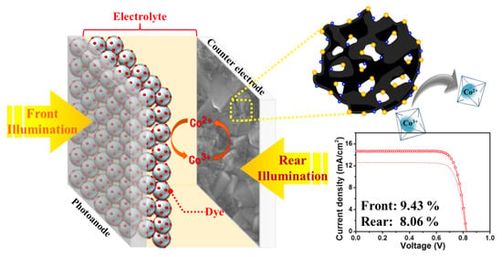
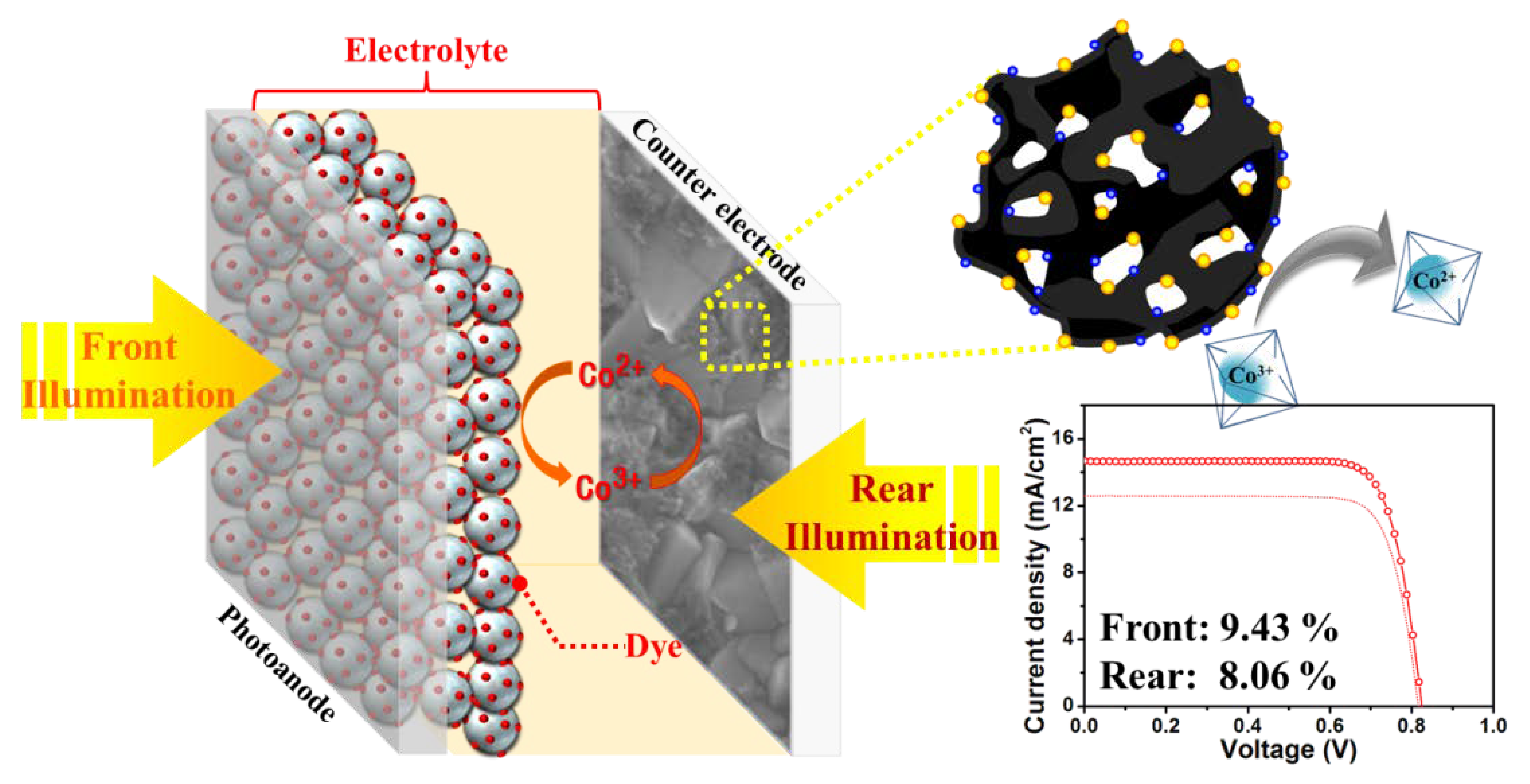
Tellurium-Doped, Mesoporous Carbon Nanomaterials as Transparent Metal-Free Counter Electrodes for High-Performance Bifacial Dye-Sensitized Solar Cells


Abstract
1. Introduction
2. Experimental Section
2.1. Materials
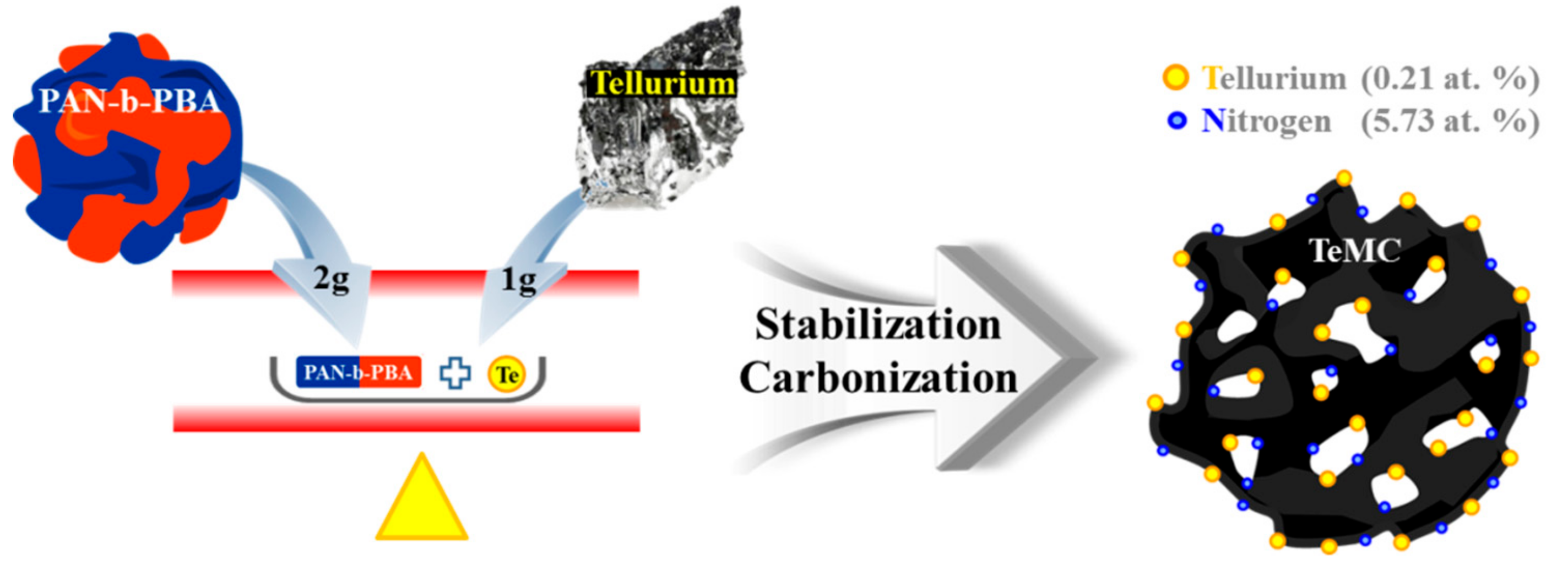
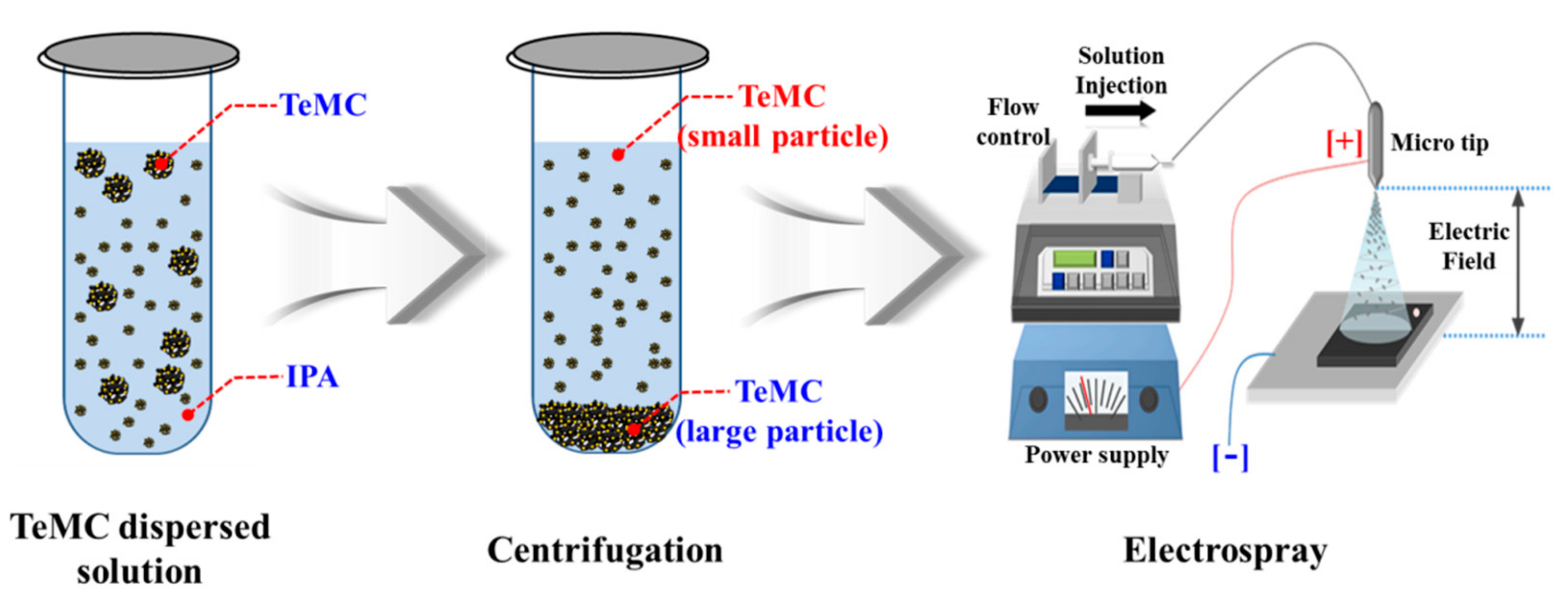
2.2. Preparation of Tellurium-Doped, Mesoporous Carbon (TeMC) Materials
3. Results and Discussion
4. Conclusions
Supplementary Materials
Author Contributions
Funding
Conflicts of Interest
References
- Oregan, B.; Gratzel, M. A Low-Cost, High-Efficiency Solar-Cell Based on Dye-Sensitized Colloidal TiO2 Films. Nature 1991, 353, 737–740. [Google Scholar] [CrossRef]
- Grätzel, M. Photoelectrochemical cells. Nature 2001, 414, 338. [Google Scholar]
- Mathew, S.; Yella, A.; Gao, P.; Humphry-Baker, R.; Curchod, B.F.; Ashari-Astani, N.; Tavernelli, I.; Rothlisberger, U.; Nazeeruddin, M.K.; Grätzel, M. Dye-sensitized solar cells with 13% efficiency achieved through the molecular engineering of porphyrin sensitizers. Nat. Chem. 2014, 6, 242–247. [Google Scholar]
- Ji, J.M.; Zhou, H.; Kim, H.K. Rational design criteria for D–π–A structured organic and porphyrin sensitizers for highly efficient dye-sensitized solar cells. J. Mater. Chem. A 2018, 6, 14518–14545. [Google Scholar] [CrossRef]
- Freitag, M.; Teuscher, J.; Saygili, Y.; Zhang, X.; Giordano, F.; Liska, P.; Hua, J.; Zakeeruddin, S.M.; Moser, J.-E.; Grätzel, M.; et al. Dye-sensitized solar cells for efficient power generation under ambient lighting. Nat. Photonics 2017, 11, 372. [Google Scholar] [CrossRef]
- Saifullah, M.; Gwak, J.; Yun, J.H. Comprehensive review on material requirements, present status, and future prospects for building-integrated semitransparent photovoltaics (BISTPV). J. Mater. Chem. A 2016, 4, 8512–8540. [Google Scholar] [CrossRef]
- Yuan, H.; Wang, W.; Xu, D.; Xu, Q.; Xie, J.; Chen, X.; Zhang, T.; Xiong, C.; He, Y.; Zhang, Y.; et al. Outdoor testing and ageing of dye-sensitized solar cells for building integrated photovoltaics. Sol. Energy 2018, 165, 233–239. [Google Scholar] [CrossRef]
- Xie, Y.; Tang, Y.; Wu, W.; Wang, Y.; Liu, J.; Li, X.; Tian, H.; Zhu, W.-H. Porphyrin Cosensitization for a Photovoltaic Efficiency of 11.5%: A Record for Non-Ruthenium Solar Cells Based on Iodine Electrolyte. J. Am. Chem. Soc. 2015, 137, 14055–14058. [Google Scholar] [CrossRef]
- Zhou, H.; Ji, J.-M.; Kang, S.H.; Kim, M.S.; Lee, H.S.; Kim, C.H.; Kim, H.K. Molecular design and synthesis of D–π–A structured porphyrin dyes with various acceptor units for dye-sensitized solar cells. J. Mater. Chem. C 2019, 7, 2843–2852. [Google Scholar] [CrossRef]
- Zhou, H.; Ji, J.-M.; Kim, M.S.; Kim, H.K. Significant Influence of a Single Atom Change in Auxiliary Acceptor on Photovoltaic Properties of Porphyrin-Based Dye-Sensitized Solar Cells. Nanomater. 2018, 8, 1030. [Google Scholar] [CrossRef]
- Yun, S.; Hagfeldt, A.; Ma, T. Pt-free counter electrode for dye-sensitized solar cells with high efficiency. Adv. Mater. 2014, 26, 6210–6237. [Google Scholar]
- Thomas, S.; Deepak, T.G.; Anjusree, G.S.; Arun, T.A.; Nair, S.V.; Nair, A.S. A review on counter electrode materials in dye-sensitized solar cells. J. Mater. Chem. A 2014, 2, 4474–4490. [Google Scholar] [CrossRef]
- Wu, J.; Lan, Z.; Lin, J.; Huang, M.; Huang, Y.; Fan, L.; Luo, G.; Lin, Y.; Xie, Y.; Wei, Y. Counter electrodes in dye-sensitized solar cells. Chem. Soc. Rev. 2017, 46, 5975–6023. [Google Scholar] [CrossRef] [PubMed]
- Xue, Y.; Liu, J.; Chen, H.; Wang, R.; Li, D.; Qu, J.; Dai, L. Nitrogen-Doped Graphene Foams as Metal-Free Counter Electrodes in High-Performance Dye-Sensitized Solar Cells. Angew. Chem. 2012, 124, 12290–12293. [Google Scholar] [CrossRef]
- Bu, C.; Liu, Y.; Yu, Z.; You, S.; Huang, N.; Liang, L.; Zhao, X.-Z. Highly Transparent Carbon Counter Electrode Prepared via an in Situ Carbonization Method for Bifacial Dye-Sensitized Solar Cells. ACS Appl. Mater. Interfaces 2013, 5, 7432–7438. [Google Scholar] [CrossRef]
- Jung, S.-M.; Choi, I.T.; Lim, K.; Ko, J.; Kim, J.C.; Lee, J.-J.; Ju, M.J.; Kim, H.K.; Baek, J.-B. B-Doped Graphene as an Electrochemically Superior Metal-Free Cathode Material As Compared to Pt over a Co(II)/Co(III) Electrolyte for Dye-Sensitized Solar Cell. Chem. Mater. 2014, 26, 3586–3591. [Google Scholar] [CrossRef]
- Nemala, S.S.; Aneja, K.S.; Bhargava, P.; Bohm, H.M.; Mallick, S.; Bohm, S. Novel high-pressure airless spray exfoliation method for graphene nanoplatelets as a stable counter electrode in DSSC. Electrochimica Acta 2018, 285, 86–93. [Google Scholar] [CrossRef]
- Cho, S.; Hwang, S.H.; Kim, C.; Jang, J. Polyaniline porous counter-electrodes for high performance dye-sensitized solar cells. J. Mater. Chem. 2012, 22, 12164–12171. [Google Scholar] [CrossRef]
- Wei, W.; Wang, H.; Hu, Y.H. A review on PEDOT-based counter electrodes for dye-sensitized solar cells. Int. J. Energy Res. 2014, 38, 1099–1111. [Google Scholar] [CrossRef]
- Khan, A.; Huang, Y.-T.; Miyasaka, T.; Ikegami, M.; Feng, S.-P.; Li, W.-D. Solution-Processed Transparent Nickel-Mesh Counter Electrode with in-Situ Electrodeposited Platinum Nanoparticles for Full-Plastic Bifacial Dye-Sensitized Solar Cells. ACS Appl. Mater. Interfaces 2017, 9, 8083–8091. [Google Scholar] [CrossRef]
- Chang, P.-J.; Cheng, K.-Y.; Chou, S.-W.; Shyue, J.-J.; Yang, Y.-Y.; Hung, C.-Y.; Lin, C.-Y.; Chen, H.-L.; Chou, H.-L.; Chou, P.-T. Tri-iodide Reduction Activity of Shape- and Composition-Controlled PtFe Nanostructures as Counter Electrodes in Dye-Sensitized Solar Cells. Chem. Mater. 2016, 28, 2110–2119. [Google Scholar] [CrossRef]
- Li, Y.; Feng, Q.; Wang, H.; Zhou, G.; Wang, Z.S. Reduced graphene oxide–Ta3N5 composite: A potential cathode for efficient Co(bpy)32+/3+ mediated dye-sensitized solar cells. J. Mater. Chem. A. 2013, 1, 6342–6349. [Google Scholar]
- Ramasamy, E.; Jo, C.; Anthonysamy, A.; Jeong, I.; Kim, J.K.; Lee, J. Soft-Template Simple Synthesis of Ordered Mesoporous Titanium Nitride-Carbon Nanocomposite for High Performance Dye-Sensitized Solar Cell Counter Electrodes. Chem. Mater. 2012, 24, 1575–1582. [Google Scholar] [CrossRef]
- Ju, M.J.; Lim, K.; Mohin, J.; Kim, H.K.; Choi, I.T.; Zhong, M.; Ko, J.; Lamson, M.; Kowalewski, T.; Matyjaszewski, K. Copolymer-templated nitrogen-enriched nanocarbons as a low charge-transfer resistance and highly stable alternative to platinum cathodes in dye-sensitized solar cells. J. Mater. Chem. A 2015, 3, 4413–4419. [Google Scholar] [CrossRef]
- Ju, M.J.; Jeon, I.-Y.; Kim, H.M.; Choi, J.I.; Jung, S.-M.; Seo, J.-M.; Choi, I.T.; Kang, S.H.; Kim, H.S.; Noh, M.J.; et al. Edge-selenated graphene nanoplatelets as durable metal-free catalysts for iodine reduction reaction in dye-sensitized solar cells. Sci. Adv. 2016, 2, e1501459. [Google Scholar] [CrossRef]
- Guo, N.; Shibuya, R.; Akiba, C.; Saji, S.; Kondo, T.; Nakamura, J. Active sites of nitrogen-doped carbon materials for oxygen reduction reaction clarified using model catalysts. Sci. 2016, 351, 361–365. [Google Scholar] [CrossRef]
- Frackowiak, E. Carbon materials for supercapacitor application. Phys. Chem. Chem. Phys. 2007, 9, 1774. [Google Scholar] [CrossRef]
- Roberts, A.D.; Li, X.; Zhang, H. Porous carbon spheres and monoliths: morphology control, pore size tuning and their applications as Li-ion battery anode materials. Chem. Soc. Rev. 2014, 43, 4341–4356. [Google Scholar] [CrossRef]
- Baptista, F.R.; Belhout, S.A.; Giordani, S.; Quinn, S.J. Recent developments in carbon nanomaterial sensors. Chem. Soc. Rev. 2015, 44, 4433–4453. [Google Scholar] [CrossRef]
- Kim, C.K.; Zhou, H.; Kowalewski, T.; Matyjaszewski, K.; Kim, H.K. Soft-templated tellurium-doped mesoporous carbon as a Pt-free electrocatalyst for high-performance dye-sensitized solar cells. ACS Appl. Mater. Inter. 2019, 11, 2093–2102. [Google Scholar]
- Duan, Y.; Tang, Q.; Liu, J.; He, B.; Yu, L. Transparent Metal Selenide Alloy Counter Electrodes for High-Efficiency Bifacial Dye-Sensitized Solar Cells. Angew. Chem. Int. Ed. 2014, 53, 14569–14574. [Google Scholar] [CrossRef] [PubMed]
- Song, D.; Li, M.; Li, Y.; Zhao, X.; Jiang, B.; Jiang, Y. Highly Transparent and Efficient Counter Electrode Using SiO2/PEDOT–PSS Composite for Bifacial Dye-Sensitized Solar Cells. ACS Appl. Mater. Interfaces 2014, 6, 7126–7132. [Google Scholar] [CrossRef] [PubMed]
- Kang, J.S.; Kim, J.; Kim, J.-Y.; Lee, M.J.; Kang, J.; Son, Y.J.; Jeong, J.; Park, S.H.; Ko, M.J.; Sung, Y.-E. Highly Efficient Bifacial Dye-Sensitized Solar Cells Employing Polymeric Counter Electrodes. ACS Appl. Mater. Interfaces 2018, 10, 8611–8620. [Google Scholar] [CrossRef] [PubMed]
- Leofanti, G.; Padovan, M.; Tozzola, G.; Venturelli, B. Surface area and pore texture of catalysts. Catal. Today 1998, 41, 207–219. [Google Scholar] [CrossRef]
- Shang, H.; Lu, Y.; Zhao, F.; Chao, C.; Zhang, B.; Zhang, H. Preparing high surface area porous carbon from biomass by carbonization in a molten salt medium. RSC Adv. 2015, 5, 75728–75734. [Google Scholar] [CrossRef]
- Jeon, I.-Y.; Kim, H.M.; Kweon, D.H.; Jung, S.-M.; Seo, J.-M.; Shin, S.-H.; Choi, I.T.; Eom, Y.K.; Kang, S.H.; Kim, H.K.; et al. Metalloid tellurium-doped graphene nanoplatelets as ultimately stable electrocatalysts for cobalt reduction reaction in dye-sensitized solar cells. Nano Energy 2016, 30, 867–876. [Google Scholar] [CrossRef]
- Kim, C.K.; Choi, I.T.; Kang, S.H.; Kim, H.K. Anchovy-derived nitrogen and sulfur co-doped porous carbon materials for high-performance supercapacitors and dye-sensitized solar cells. RSC Adv. 2017, 7, 35565–35574. [Google Scholar] [CrossRef]
- Hou, Y.; Wang, N.; Yang, X.H.; Fang, W.Q.; Zhang, B.; Wang, H.F.; Lu, G.Z.; Hu, P.; Zhao, H.J.; Yang, H.G. Rational screening low-cost counter electrodes for dye-sensitized solar cells. Nat. Commun. 2013, 4, 1583. [Google Scholar] [CrossRef]
- Kang, S.H.; Jeong, M.J.; Eom, Y.K.; Choi, I.T.; Kwon, S.M.; Yoo, Y.J.; Kim, J.; Kwon, J.; Park, J.H.; Kim, H.K. Porphyrin sensitizers with donor structural engineering for superior performance dye-sensitized solar cells and tandem solar cells for water splitting applications. Adv. Energy Mater. 2017, 7, 1602117. [Google Scholar] [CrossRef]


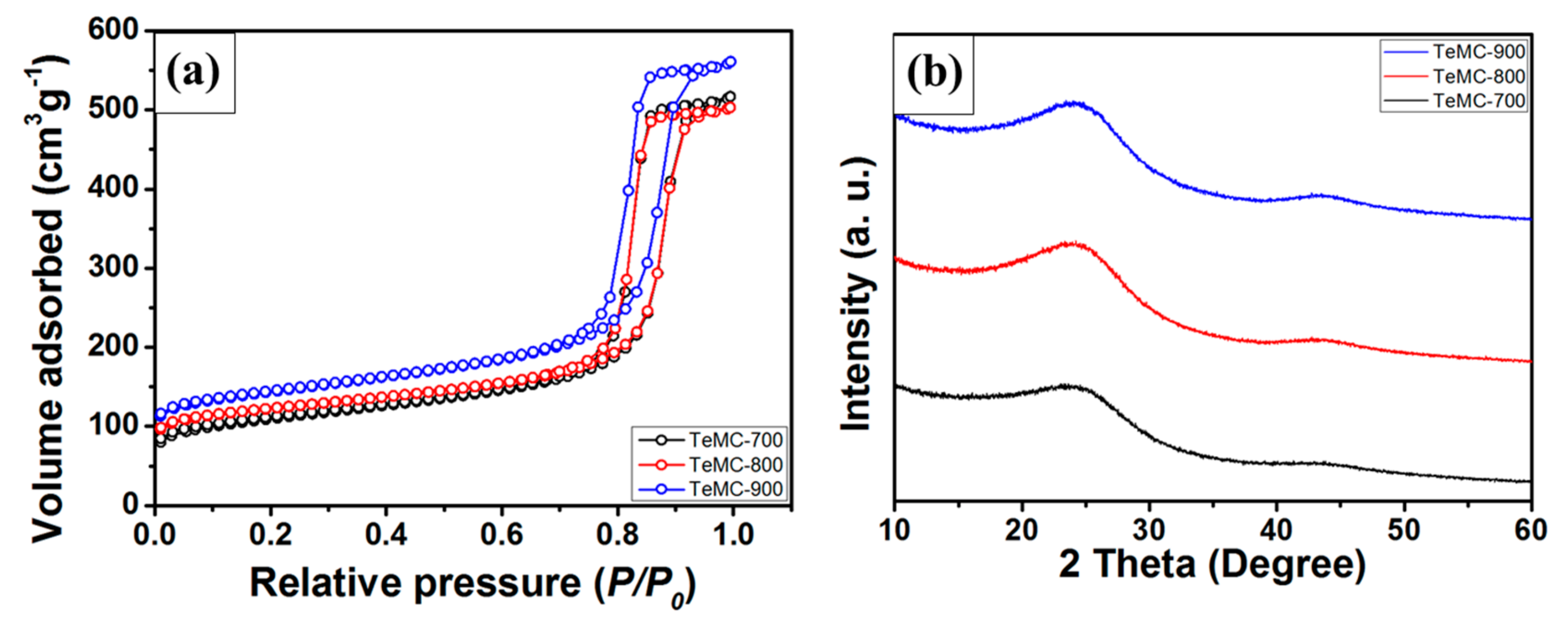
| Sample | SBET (m2 g−1) | Vtotal (cm3 g−1) | Vmicro (cm3 g−1) | Vmeso (cm3 g−1) | Pore Size (nm) |
|---|---|---|---|---|---|
| TeMC-700 | 399.68 | 0.80 | 0.08 | 0.73 | 12 |
| TeMC-800 | 455.05 | 0.78 | 0.11 | 0.68 | 12 |
| TeMC-900 | 526.79 | 0.87 | 0.12 | 0.75 | 11 |
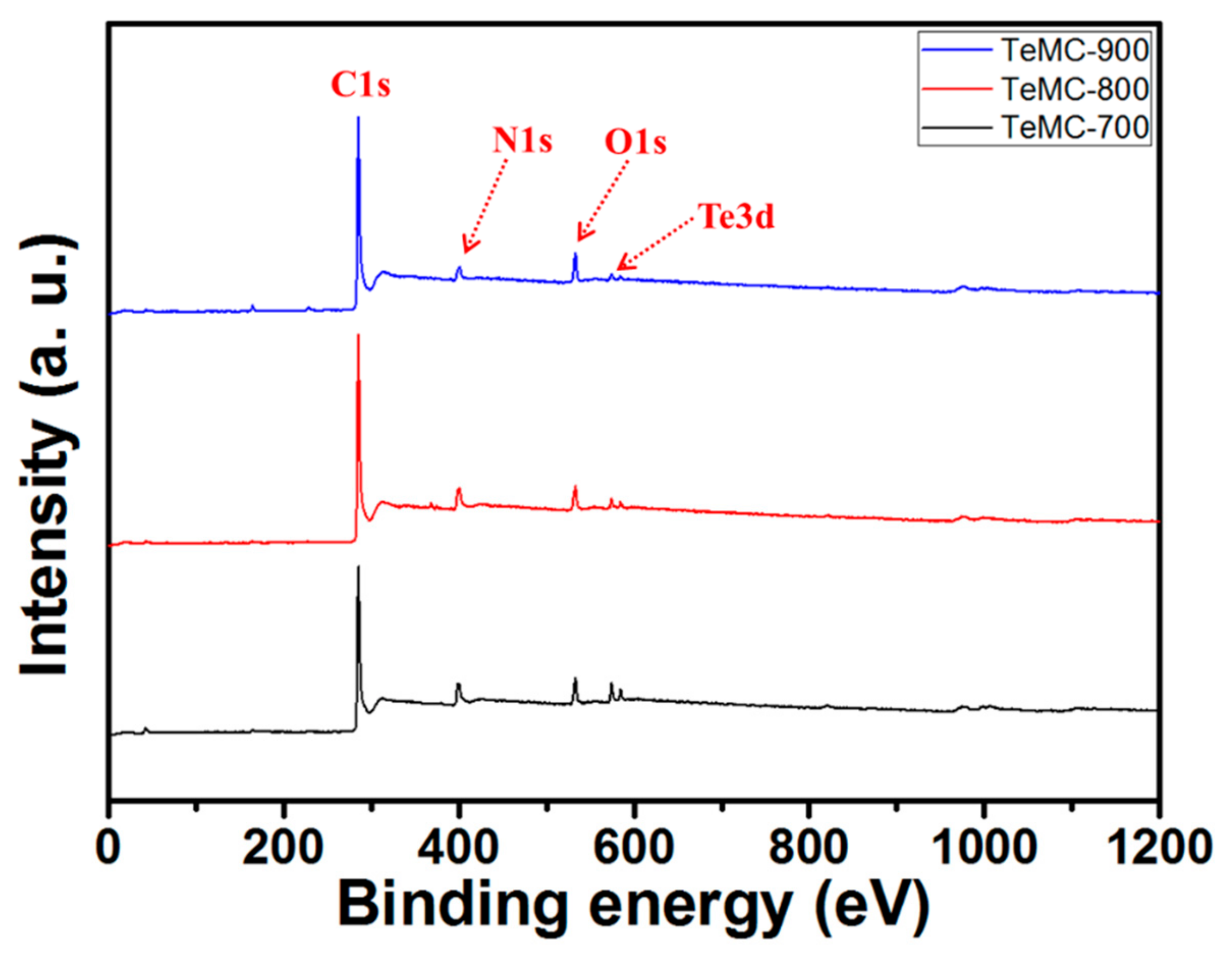
| Sample | Element (at.%) | |||
|---|---|---|---|---|
| C | O | N | Te | |
| TeMC-700 | 83.63 | 5.80 | 10.01 | 0.55 |
| TeMC-800 | 86.34 | 5.04 | 8.36 | 0.26 |
| TeMC-900 | 87.47 | 6.40 | 5.73 | 0.21 |
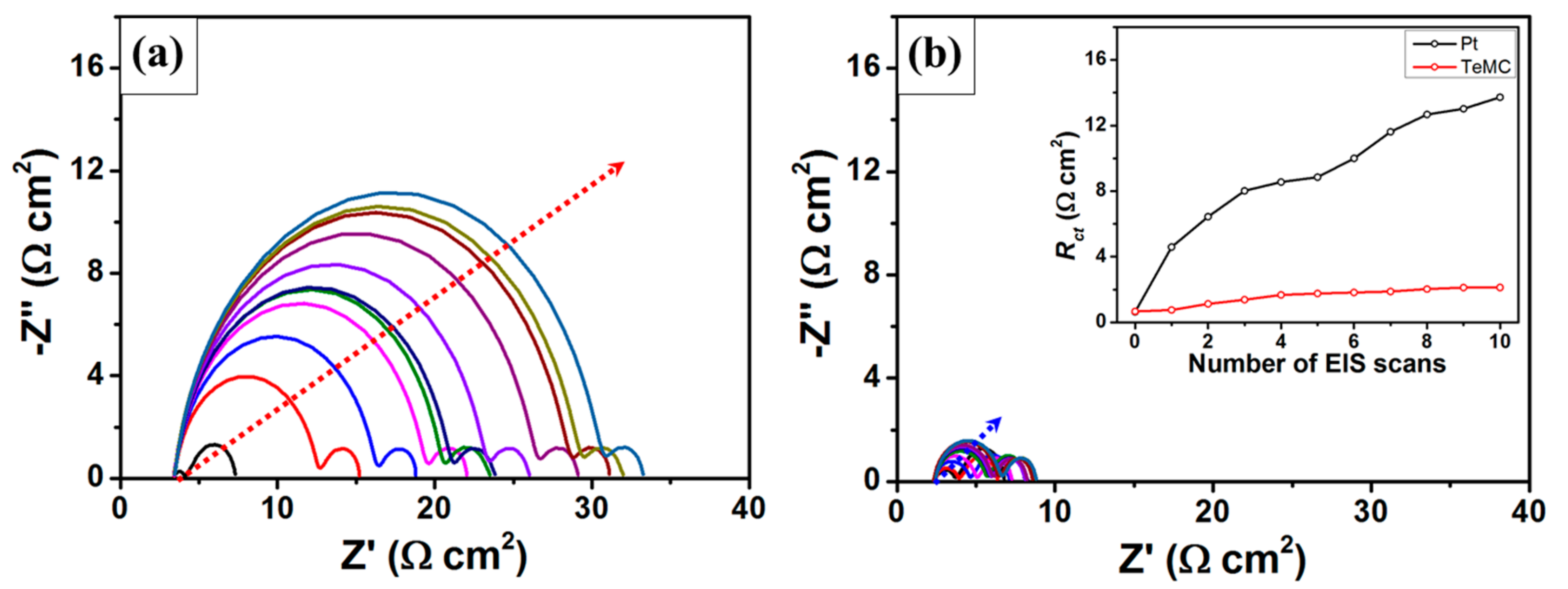
| LSV | EIS | ||||||
|---|---|---|---|---|---|---|---|
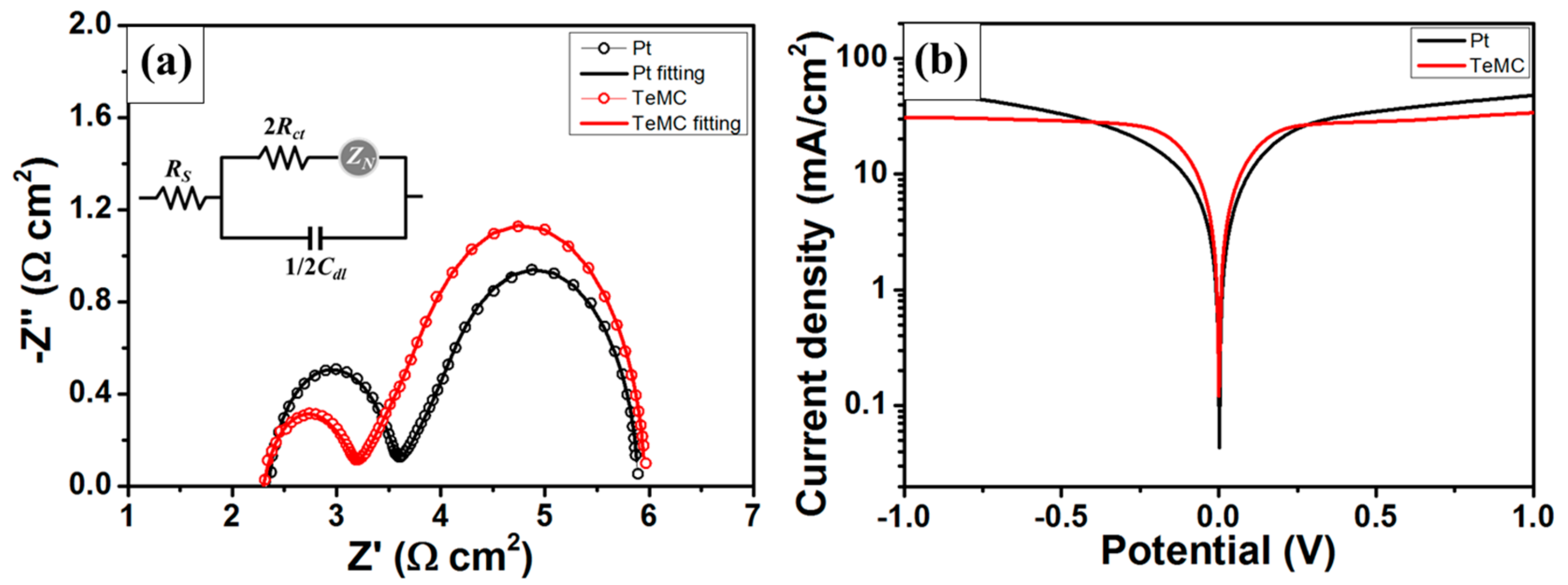
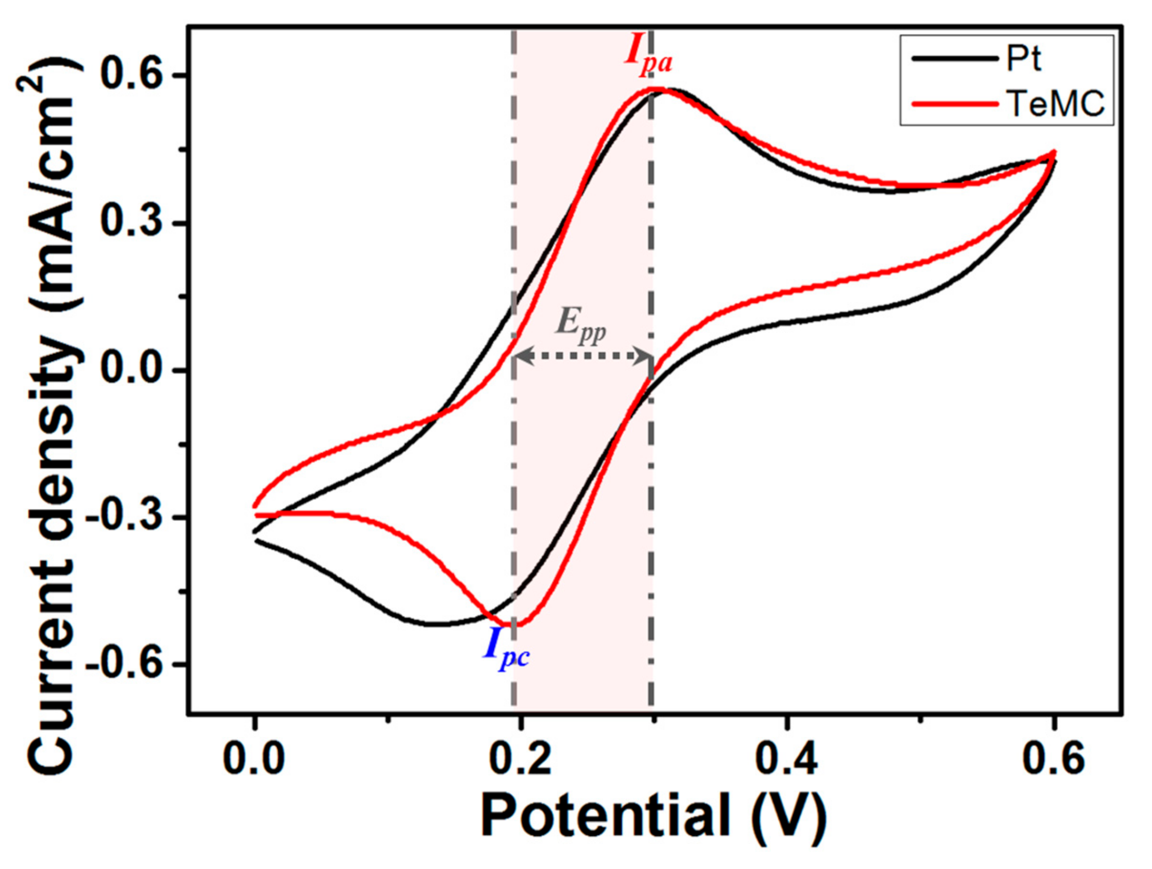
| CE | Electrolyte | RCV (Ω cm2) | Jo (mA cm−2) | Rs (Ω cm2) | Rct (Ω cm2) | Cdl (μF cm2) | Jo (mA cm−2) |
| Pt | Co(bpy)32+/3+ | 9.37 | 2.74 | 2.30 | 0.62 | 14.38 | 41.44 |
| TeMC | 6.87 | 3.74 | 2.17 | 0.49 | 28.91 | 52.43 | |
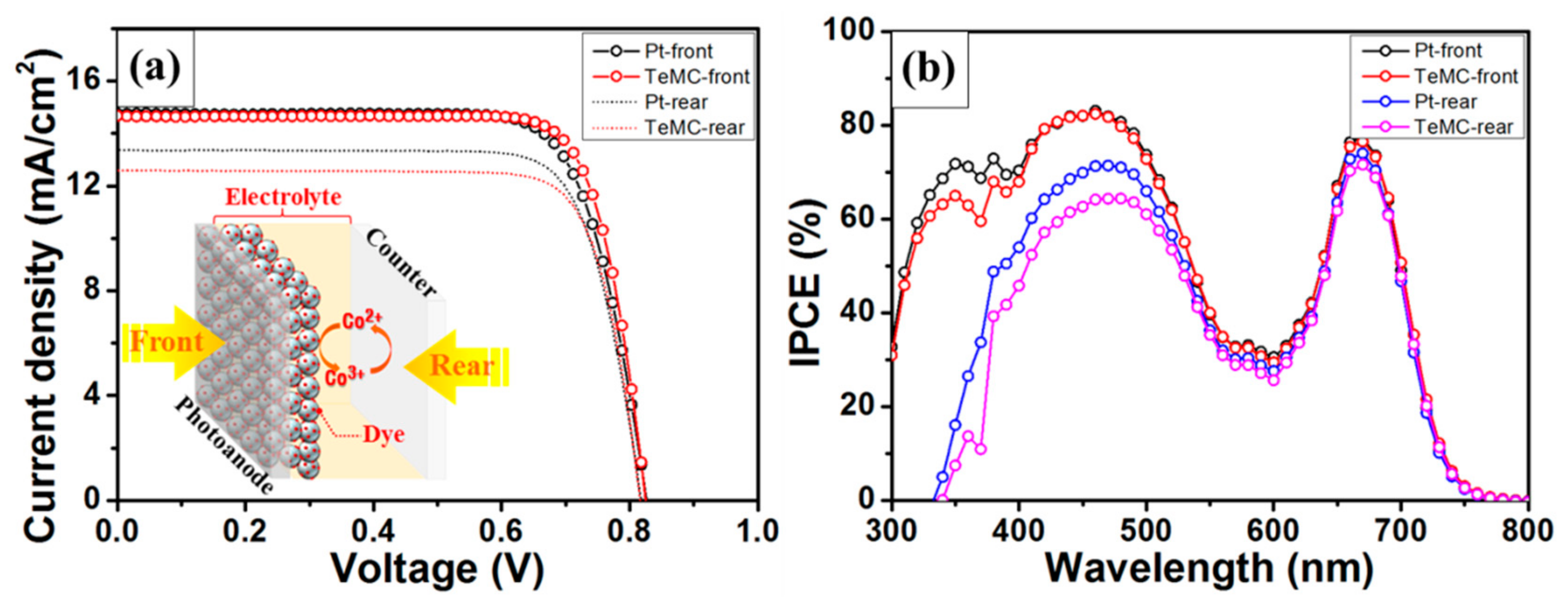
| Sample | Dye/Electrolyte | JSC (mA cm−2) | VOC (mV) | FF (%) | PCE (%) * |
|---|---|---|---|---|---|
| Pt-front | SM315/Co(bpy)32+3+ | 14.58 ± 0.11 | 820.51 ± 4.86 | 77.13 ± 0.57 | 9.23 ± 0.07 |
| TeMC-front | 14.48 ± 0.12 | 822.14 ± 3.73 | 79.23 ± 0.23 | 9.43 ± 0.10 | |
| Pt-rear | 13.25 ± 0.14 | 817.00 ± 1.43 | 77.78 ± 0.10 | 8.42 ± 0.08 | |
| TeMC-rear | 12.52 ± 0.11 | 813.38 ± 3.04 | 79.13 ± 0.25 | 8.06 ± 0.09 |
© 2019 by the authors. Licensee MDPI, Basel, Switzerland. This article is an open access article distributed under the terms and conditions of the Creative Commons Attribution (CC BY) license (http://creativecommons.org/licenses/by/4.0/).
Share and Cite
Kim, C.K.; Ji, J.-M.; Zhou, H.; Lu, C.; Kim, H.K. Tellurium-Doped, Mesoporous Carbon Nanomaterials as Transparent Metal-Free Counter Electrodes for High-Performance Bifacial Dye-Sensitized Solar Cells. Nanomaterials 2020, 10, 29. https://doi.org/10.3390/nano10010029
Kim CK, Ji J-M, Zhou H, Lu C, Kim HK. Tellurium-Doped, Mesoporous Carbon Nanomaterials as Transparent Metal-Free Counter Electrodes for High-Performance Bifacial Dye-Sensitized Solar Cells. Nanomaterials. 2020; 10(1):29. https://doi.org/10.3390/nano10010029
Chicago/Turabian StyleKim, Chang Ki, Jung-Min Ji, Haoran Zhou, Chunyuan Lu, and Hwan Kyu Kim. 2020. "Tellurium-Doped, Mesoporous Carbon Nanomaterials as Transparent Metal-Free Counter Electrodes for High-Performance Bifacial Dye-Sensitized Solar Cells" Nanomaterials 10, no. 1: 29. https://doi.org/10.3390/nano10010029
APA StyleKim, C. K., Ji, J.-M., Zhou, H., Lu, C., & Kim, H. K. (2020). Tellurium-Doped, Mesoporous Carbon Nanomaterials as Transparent Metal-Free Counter Electrodes for High-Performance Bifacial Dye-Sensitized Solar Cells. Nanomaterials, 10(1), 29. https://doi.org/10.3390/nano10010029