1. Introduction
In recent decades, renewable energy has become a very attractive solution because it is inexhaustible, non-polluting, and highly adapted to decentralized generation [
1,
2,
3]. Indeed, technologies are currently being developed to use this energy on a daily basis [
4,
5]. Exploitation for the production of electricity is very profitable in isolated areas where the extension of the power grid is very expensive. It appears that wind generators are a good alternative for supplying the required energy with affordable prices. These generators are usually equipped with induction machines, which are widely used because of their robustness and the reduced cost of maintenance [
6,
7,
8].
However, independent wind systems do not produce effective energy for a long time during the year. This is explained by the fact that the wind and solar systems have unpredictable behavior and depend on weather and climatic changes, particularly when they are used independently [
9,
10]. Also, they must be oversized to make them totally consistent. To overcome these difficulties, we must resort to renewable energy hybrid systems. Indeed, the use of the wind and the solar PV hybrid system with battery storage is recommended [
11]. Such systems are usually equipped with diesel generators to meet the peak load when there is a deficiency of available energy to ensure the requested power in isolated areas [
12]. The combination of the solar PV and wind generation system is considered very good alternative, especially in the case of stand-alone applications [
13].
Consequently, the use of the renewable energy sources in a hybrid system reduces combustion of fossil fuels and CO
2 emission. This strategy may preserve the environment [
14]. To increase the reliability and efficacy of the system, current solutions use the combination of several renewable energy sources, such as photovoltaic and wind generators. For better energy stability and autonomy, other sources can be added, such as batteries and fuel generators [
15,
16]. In this case, the drawbacks of one source can be supplemented by the advantages of the other source. Hence, more economical operation of such a hybrid system can be achieved [
17]. A robust operating of the integrated system can be reached and the size of energy storage can be reduced [
18,
19,
20]. To prevent the generator from stalling during operation in isolated mode, adjustments to the parameters of the wind turbine are necessary. However, these adjustment techniques when it comes to remote sites does not exactly optimize the quality of the voltage and can cause the instability of the voltage even its breakdown. These drawbacks are due to the reverse nature of the problem. Indeed, in the case of such system, the angular frequency, the voltage, and the slip are not given if the latter operates in remote area [
21,
22].
Some studies present the use of complex techniques to stabilize the voltage. These techniques are based on synchronous compensators, sliding mode controllers or pulse width-modulated inverters [
23,
24]. However, these solutions are not adapted in the remote sites and do not take in consideration the machine parameters to consider its safe operating area (SOA) [
25]. Consequently, to solve the unstable operation of the wind turbine generator a new approach is described in this paper. This procedure treats the behavior of a self-excited induction generator (SEIG) which is incorporated into an isolated site hybrid system. This system integrates the advantages of the preferred operating point with those of electronic controllers. This work presents a dynamic and steady state analysis of a hybrid solar and wind system with batteries storage. The importance of the merging of several renewable energy sources will be detailed to give the hybrid system more stability.
The contribution of this work consists of developing a consistent procedure and a testing process to investigate an induction generator operating as integrated source in a low power multisource. This strategy can prevent the generator demagnetization following a sudden stall. The suggested procedure allows for widening of the operating range of frequency and slip. Consequently, it increases the SOA where the best stability of the SEIG can be obtained. Extensive simulation will be presented, analyzed, and compared with experimental results obtained from carried out tests.
2. Multisource System Configuration
The SEIG integration in an isolated multisource system presented in this work is shown in
Figure 1. This system is built around a diode rectifier and a chopper which enables the connection of the SEIG to a DC bus. In this scheme, the battery imposes the bus DC voltage level and the photovoltaic source is one of the multisource systems which can be connected to the DC bus.
The connection of a diesel generator is possible and can be realized if it is needed to ensure the sustainability of power delivery. As a load, a resistive (heating) load and an induction motor (pump) are considered. The capacitor bank C delivers the reactive power consumed by the induction generator (IG) as well as the neighboring loads. In this work, the objective was focused on limiting the variation of the R and C parameters when the generator is coupled to a local multisource system. The determined SOA takes into account the voltage stability and the IG energetic performance.
3. Steady State Evaluation of Induction Generator
To establish the analytical study of the considered induction generator, one uses the single phase equivalent circuit shown in
Figure 2 [
26]. In this figure, one notes the presence of the capacitor
C connected in parallel with the
R-L load.
In this model, the iron losses are neglected and the various parameters are defined in
Appendix A. The various parameters of IG and that acting in
Figure 2 are determined using the conventional no load and blocked rotor experiments. The equations which govern the SEIG operation are given by:
Taking into account the time phasor diagram related to the equations system (1), the following equations can be obtained.
where, the constants A”, B, D”, E”, A’, D’, and E’ are defined in the
Appendix A. the resolution of the equations system (2) leads to the following solutions:
and
The analysis of Equations (2)–(4) can conclude that the angular speed ω and the slip s are influenced only by the load and the induction machine parameters. Thus, the SEIG will be locked on fixed ω and s when these elements are fixed.
4. Safe Operating Area Delimitation
To define the exact values of ω and s solution of equations system (2), an iterative Newton–Raphson, PSO algorithm, or graphical methods [
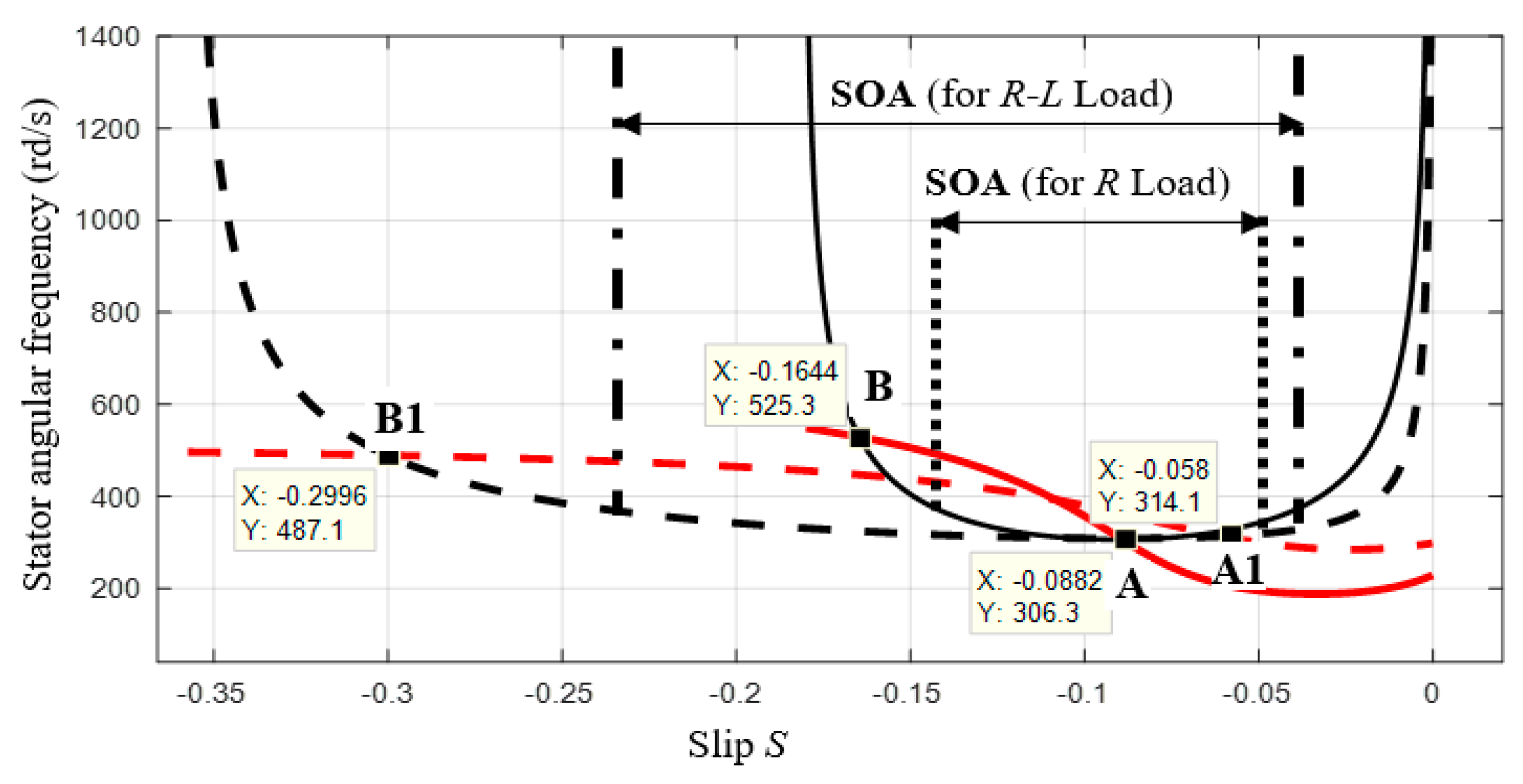
27] can be used to solve the given equations system. The ω solutions expressed by Equations (3) and (4) for an
R-L load are graphically shown in
Figure 3. In this figure, the
R load characteristics are represented by a continuous line but those of the
R-L load are represented by a dashed line. This study has been carried out considering the IG parameters defined in the
Appendix A. The used
R-L load is characterized by the following values:
R = 111 Ω,
L = 0.17 H and
C = 87.5 µF. On the other hand, for the resistive load we took the following values:
R = 76 Ω, and
C = 38 µF. From the time when the operating points are given by the intersections of ω
1 (Equation (3)) with ω
2(1) (Equation (4)) and ω
2(2) (Equation (4)), it is clear that there are only two operating points which have to be retained for each load. The first operating point is placed in the flattened part of the curve located around ω
min where the changes of ω are relatively limited. In this study, the first operating point is ‘A’ for the
R load and ‘A1′ for
R-L load. ω
min is the minimal angular frequency at the output of the stator and is given by:
where s
min is given by:
This zone, designated as the SOA, is limited on the right by the increase of the frequency. However, on the left, it is limited by considering the SEIG energetic performances explained by the limited critical slip expressed as:
The second operating point, noted ‘B’ for R load and ‘B1′ for R-L load will not be taken into account since its characteristics (ω and s) have high values which may destroy the energetic performances of the generator. In addition to that, this operating point is placed in the unstable zone far from the SOA.
From the analytical developments, one can remark upon a possible variation zone of the slip named SOA. In this area, the angular frequency is kept at constant values and the IG maintains its stability towards the sudden load changes or wind power variations. Considering
Figure 3, one can conclude that the flattened part of the curve, where the stator angular frequency kept quasi constant, is the largest in the case of the
R-L load. This can be considered an advantage if there are no adverse effects on the energy performance of the induction generator. In this case, the stability of the generator operating can be improved as the range of SOA is extended. Hence, the generator is permitted to operate in complete safety and with its maximum energy efficiency.
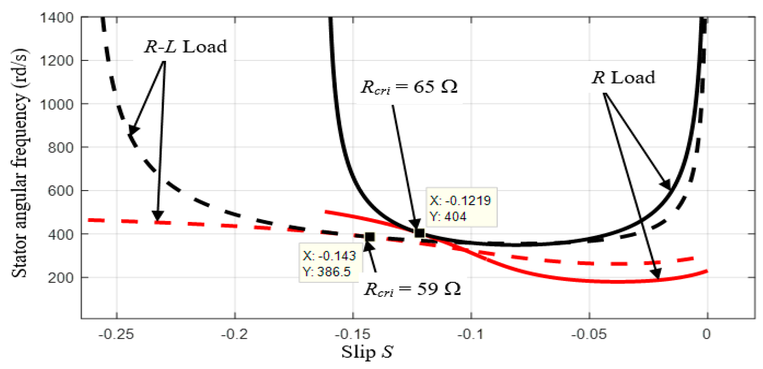
5. Impact of the Load Variation
Figure 4 presents the case where the capacitor
C is maintained constant but the resistive load varies. In this case, decreasing
R to the limited value noted
Rcri = 65 Ω leads to an operating point where the curves are tangent at a point whose ω is 404 rd/s (64.33 Hz). However, in the case of
R-L load,
R decreases to the critical value
Rcri = 59 Ω.
The operating conditions are limited. In this case, the IG lost its energy performances and the voltage stability is rapidly lost in transient state. From the analysis of
Figure 3 and
Figure 4, one can remark that the presence of an
L inductive load in the system allows the increase of the stability area where the SEIG can operate under load sudden changes or wind power variations. It is clear that the generator can be more loaded in the presence of the inductive load and that
R can reach 59 Ω. In contrast, we cannot go below the value 65 Ω in the case where the load is purely resistive. A resistive
R load enables a more limited interval variation of operating points and the use of a fixed capacitor increases the SEIG instability. For these reasons, it is necessary to operate with a variable capacitor to make sure that the generator works at maximum efficiency and the operating point does not exceed the SOA.
6. Simulation Model
To develop an adequate model for the considered induction generator, we assume some simplifying hypotheses, such as neglecting iron losses, supposing that resistances are independent of temperature, and considering that there are no saturation effects. Consequently, a simple model is used to make easy numerical development and decrease of time simulation. The presented model is made using space phasor formalism, considering that the stator and rotor spatial reference (
and
) are linked to the stator and rotor phase 1 axes. Let us symbolize
the stator variables which is defined relatively to
. The rotor variable which is defined relatively to
will be represented by
. The stator variable given relatively to the spatial reference
is denoted
. So, one can get
from
by means of the variable change
Therefore, the generator will be characterized by the equations system (8). These equations are given in the rotor reference frame and they are presented by:
where
,
, and
represent the fluxes linked by the stator, the rotor and the fictitious windings, respectively, expressed by:
Using Equations (1) and (2), the stator voltages is given by:
As the voltage at the rotor coil output is null, from the second equation of (1) the current in the stator can be written as:
Moreover, it is essential to consider the mechanical relationship to develop the generator model during transients and steady states. Considering
the overall system inertia, the mechanical relationship is given by:
where
represents the machine friction and windage torque and
the torque that acts on the shaft of the generator.
is the torque defined by the following cross product:
7. Experimental Test Bench Configuration
Let us consider a multisource system in the isolated sites which look like an agglomeration of a few houses and farms which require a low power. It is preferable in this case to provide the reliability of the system and the continuity of the power supply. Consequently, to guarantee these priorities, the SEIG must be used in a stable operating zone and the transient state can be enhanced using a complementary supply source. This situation will be reached when the SEIG is integrated into the multi-source system presented in
Figure 1. The corresponding experimental test bench is shown by
Figure 5. After starting, the operating point of the induction generator can be changed with load variations.
To ensure the various tests, a laboratory test bench is used. The latter is made up of an Induction machine connected to a DC Bus through a diode rectifier and associated filter. A DC voltage source realized by means of an autotransformer, a rectifier and a filter. The use of the autotransformer is necessary to modify and to set the bus voltage at the requested level. The experimental study aims to define the limits and the SOA in which the SEIG is stable when it is connected to the DC bus. Consequently, the IG will be protected from high damaging transients that occurs during sudden changes in load or unexpected wind power variation. The DC motor is used, as a prime mover, to drive the induction motor (IM) which will operate in the generator mode. Another autotransformer and an additional diode rectifier PD6 are used to supply the DC Bus. A variable R load enables power variations from 5% to 25% of the total power of 2 kW. A capacitor bank changing from 5 µF to 180 µF provides variation of the necessary reactive power to the machine.
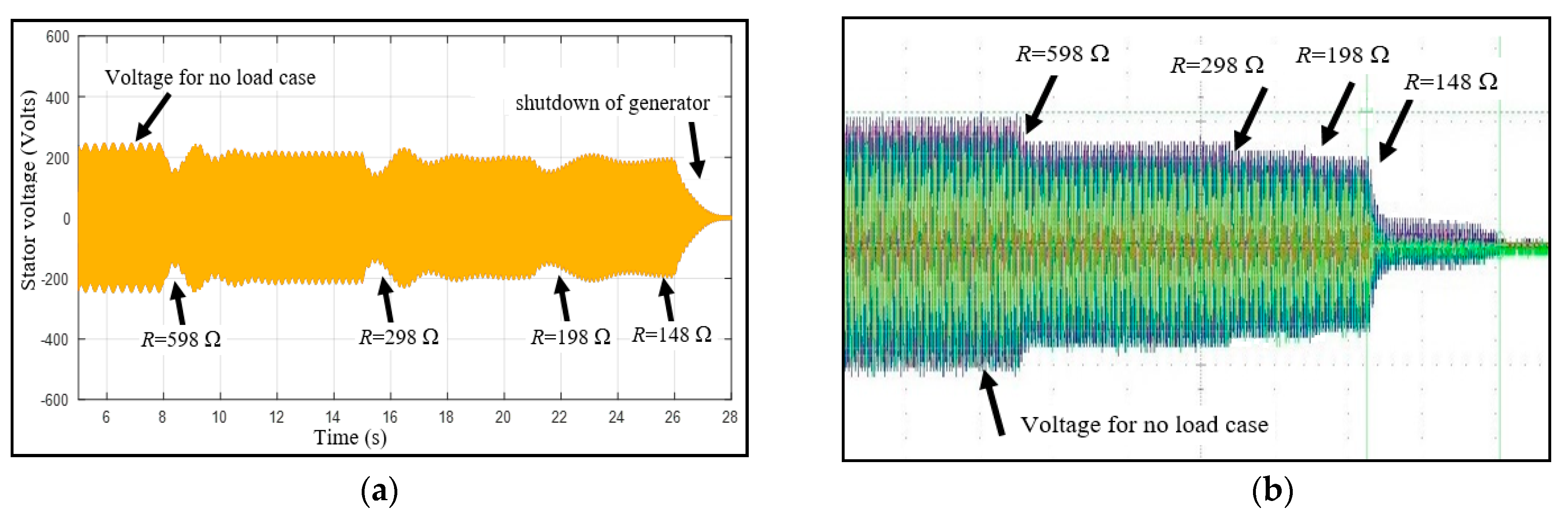
8. Experimental Results
The analytical results presented in
Figure 3 and
Figure 4 show that the inductive load enhances the stability of the induction generator operating during the transient state. Therefore, this study takes into account the most critical case in which only
R load varies.
Figure 6a,b present the SEIG stability obtained for a decrease of
R from no load to 198 Ω load corresponding to 15% of 2 kW at constant reactive power operation. Here, the SEIG is not connected to the DC bus and the capacitor
C is kept at a constant value.
The next step consists on the SEIG operating while connecting to the microgrid. In this case, a step-down shopper is used via a diode rectifier to stabilize the voltage at the value of the DC bus.
Figure 7a,b show the simulation and experimental results obtained in the case of the SEIG connection to the DC bus. The
R load variation starts from no load case to that where R = 198 Ω. One can note that the voltage at the IG output decreases slightly. To examine the SEIG stability, the tests are repeated by changing the load to 119 Ω (25% 500 W) and to 60 Ω (50%, 1000 W).
It is remarked that the voltage level decreases with balancing at the DC bus voltage set to 220 V upon application of 10% of the load. The stability of the machine is improved and it is maintained for 50% of the load variation corresponding to
R = 60 Ω. However, a greater variation of the load leads to a voltage collapse and the machine dropping out. This case presented in
Figure 8a,b corresponds to
R = 37 Ω.


