Abstract
The use of Computational Fluid Dynamics (CFD) to assist in air quality studies in urban environments can provide accurate results for the dispersion of pollutants. However, due to the computational resources needed, simulation domain sizes tend to be limited. This study aims to improve the computational efficiency of an emission and dispersion model implemented in a CPU-based solver by migrating it to a CPU–GPU-based one. The migration of the functions that handle boundary conditions and source terms for the pollutants is explained, as well as the main differences present in the solvers used. Once implemented, the model was used to run simulations with both engines on different platforms, enabling the comparison between them and reaching promising time improvements in favor of the use of GPUs.
1. Introduction
Since the industrial revolution, cities have grown at an outstanding pace, leading not only to an increase in population density, but also in the emissions to be found in a city as industrial and vehicle emissions appeared. Given that the urban landscape generates poor dispersion conditions, high pollution concentration areas are generated, representing a health hazard to inhabitants and a threat to the environment in general. Therefore, the study of air quality in cities is of the utmost importance for ensuring a safe living environment.
A wide range of studies concerning pollutant dispersion can be found in the literature, dealing with a wide variety of emissions from different sources [1,2,3,4,5]. In order to study this phenomenon through numerical modeling, various approaches have been considered [6], among which Computational Fluid Dynamics (CFD) represents one of the most used, with promising results for diagnosis and forecast of concentration fields under different weather conditions on complex domains [7,8,9]. The main advantage of CFD over other methods are the space and time resolutions that can be achieved, as well as the accurate consideration of flow dynamics. However, due to the computational power needed, domain sizes are limited, as is the resolution. This problem has led to research efforts towards improving the computational efficiency combining advances in hardware technology, new numerical methods, and programming techniques, generically regarded as the field of High Performance Computing (HPC). The relatively recent incorporation of secondary processors in the HPC landscape has led to a significant increase in raw computing power available for numerical simulation solvers at decreasing costs.
Particularly, over the last fifteen years, Graphics Processing Units (GPUs) have shown an outstanding evolution, not only in terms of computational power, but also in terms of capacity and flexibility for programming, since the release of CUDA (Compute Unified Device Architecture) [10] by NVIDIA in 2007 allowed the programming of multi-processors to execute parallel algorithms through the SPMD paradigm (Single Program–Multiple Data). Since then, scientists have studied the use of GPUs to tackle general problems [11], as well as numerical linear algebra problems [12,13], reaching significant improvements in performance in these last studies. Since most CFD codes are limited in performance by memory bandwidth rather than by floating point operations throughput, the huge memory bandwidth available in GPU processors has significantly allowed for performance improvements in CFD codes. Accessing this great computational power comes at an expense, however, since a significant portion of the code requires being adapted to GPU computing and rewritten in suitable languages such as CUDA and/or OpenCL.
As far as Computational Fluid Dynamics are concerned, several studies have been conducted incorporating the use of GPUs, since this parallelization technique has proven to have many benefits in terms of speedup and energy consumption [14]. Nonetheless, most studies still struggle with challenges when it comes to memory access optimization and data transfer between the CPU and the GPU, among other things [14], proving that there is room for further programming improvements regarding these technologies.
The use of graphics processors on CFD solvers dates even before the introduction of CUDA, with different solvers being ported to GPUs by other means. Such is the case of [15], where a Lattice Boltzman solver was implemented on GPUs to solve the pollution dispersion in an urban environment. Moreover, due to the high data parallelism found in the Lattice Boltzman Method, further studies have been conducted implementing different models in the GPUs, as in the cases of Fluid–Solid interaction [16,17,18] and multi-domain grid refinement [19], to name a few, always achieving time improvements when using GPUs.
Apart from this method, there has also been interest in the migration of other Navier–Stokes solvers, as in the case of [20,21,22]. All of these studies present the passage of a finite difference solver to a multi-GPU platform, using a similar parallelism strategy to the one described in this paper, recurring to the use of CUDA and the Message Passing Interface (MPI) library to handle the different levels of parallelisms present in the solvers, reaching speedups of up to two orders of magnitude when compared to the sequential version of the solver.
When it comes to the finite volume method—as the one described in this study—[23] presents a GPU implementation of an unstructured mesh-based finite volume Navier–Stokes solver, using the CUDA programming model and the MPI library and reaching speedups of up to 50 times. Similarly to [23], the present study aims to present a new version of an existing CPU-only-based solver CFD code that incorporates the use of the GPU as a part of a larger effort to generate a general purpose CFD code that allows computations to be done in graphics processing units or by central processing units.
In this work, the migration of an open-source general purpose code to Heterogeneous Computing, applied for the computation of pollution dispersion in urban environments, is presented. The different strategies used to incorporate the use of GPUs are explained for this particular application but are not limited to it, as the final code already uses several models, which include turbulence models and fluid–solid interaction models, among others, resulting in a multiphysics open-source code capable of simulating a wide range of situations with the aid of GPUs, leading to important improvements as far as computational efficiency is concerned.
Section 2 presents the Methodology, which includes the description of the different CFD solvers used for the simulations, the CPU-based version, and the new version that incorporates GPUs. Then, the tracer transport capabilities that were migrated from one platform to the other are explained to show the study case methodology in Section 3. In Section 4, some results from both simulation engines are shown, and computation time is compared between both solvers on different platforms. Finally, in Section 5, the conclusions are reached, and possible future work is presented.
2. Methodology
2.1. Simulation Engines
The solvers used were both in-house open-source codes that solve three-dimensional turbulent flows with the finite volume method, with second accuracy in space and time. The CPU-based code is called caffa3d.MBRi [24,25], and was used as a base for the generation of the second solver that incorporates the use of GPUs [26]; therefore, they both use the same mathematical models when solving the flow and transport equations. Simulation results from both codes for any one setup should match up to round off error. This feature provides a smooth path for debugging the GPU-based solver with straightforward correctness checks relative to the CPU solver.
2.1.1. CPU-Based Solver
This simulation solver is based on a family of 2D flow solvers contained in the textbook by Ferziger and Peric [27], and has had many improvements and additions since its creation, starting with its extension to 3D in 2004 [24]. The code is written in Fortran 90, making it an accessible solver for scientists that are not that familiar with computer sciences.
The solver caffa3d.MBRi is a general purpose open-source fully implicit code that implements the finite volume method for solving Navier–Stokes equations. The incompressible flowsolver aims at providing a useful tool for numerical simulation of real-world fluid flow problems that require both geometrical flexibility and parallel computation capabilities to afford tens and hundreds of millions of cell simulations. Geometrical flexibility is provided in this model by using a block-structured grid approach combined with the immersed boundary condition method [28] to address even the most complex geometries with little meshing effort and preserving the inherent numerical efficiency of structured grids [29,30].
The same block-structured framework provides the basis for parallelization through domain decomposition under a distributed memory model using the MPI library. A compact set of encapsulated calls to MPI routines provides the required high level communication tasks between processes or domain regions, each comprised of one or several grid blocks.
The solver has been applied and validated in several different fields, including wind energy and wind turbine simulations [31], blood flow in arteries [32], and atmospheric pollutant transport [25,33]. For a full description of the solver capabilities, please see [25].
The code consists mainly of a package of Fortran 90 modules that contain a wide range of capabilities that are to be called when needed. The parallel CPU computing approach is based on domain decomposition and MPI communication, while at each domain sub-region, serial single core CPU-only-based code is run, meaning that each core will be solving the flow at its sub-region in a serial way. Thus, within each sub-region, most solver routines deal with cell-level computations organized in loops through the entire sub-domain. Little simultaneous dependency between neighbor cells occurs, except for the linear solver required due to the semi-implicit nature of the code.
The mathematical model comprises the mass balance and momentum balance equations, Equations (1) and (2), for a viscous incompressible fluid (laminar or turbulent) with a generic non-reacting scalar transport equation, Equation (3) for scalar field with diffusion coefficient . This last equation was used here for implementing the Tracers Module (explained below) to compute pollutant dispersion.
In these equations, is the fluid velocity, is the density, is the thermal expansion factor, T is the fluid temperature and is a reference temperature, g is the gravity, p is the pressure, is the dynamic viscosity of the fluid, and D is the strain tensor. The balance equations are written for a region , limited by a closed surface S. The Equation (2) has been written here only for the first Cartesian direction.
The discretized version of the model consists of applying the previous equations to each volume element of the mesh, giving an expression in the form of Equation (4), written again for the u velocity component, where the variable value at cell P is related to the values at the six neighbors.
In Figure 1, a scheme of the iterations executed in order to solve each linearized equation for each timestep is shown. Complete details for the discretization of each term will not be given here, but can be found in Usera et al. (2008) [24].
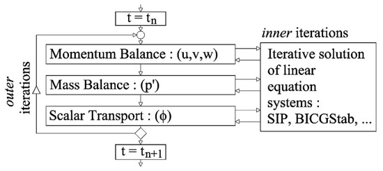
Figure 1.
caffa3d.MBRi iteration scheme, Usera et al. (2008) [24].
For this particular study, the parametrization of turbulence was performed with a simple Smagorinsky large eddies simulation model, and the buildings present in the domain were represented by the Immersed Boundary Method; capabilities that were already implemented in the GPU version are described in the next subsection.
2.1.2. CPU–GPU-Based Solver
The original CPU solver is currently being ported to the GPU, with about three quarters of the different physical modules already functional in the GPU, including all the general purpose capabilities. This effort is based on a preliminary study of GPU efficiency applied to the Strongly Implicit Procedure (SIP) linear solver [34], where cell arrangement by hyper-planes was explored in order to reduce data dependencies in heptadiagonal linear solver iterations. Some specialized modules, like Volume Of Fluid (VOF) and Wind Turbine models, remain to be ported.
This migration of the code was designed to produce a GPU-based version of the CPU-based solver, with equivalent implementations of all the relevant computations up to round-off error. The resulting package hosts both versions of the solver, which share about 40% of the original Fortran 90 source code. Compilation, through a parameterized hybrid Makefile, was configured to produce two independent versions of the solver, one that computes solely based on CPU, and another that incorporates the use of GPUs for computations. The main advantage of this approach is that it enables the programmer to debug the new solver by comparing results with its own CPU version, which consists of a reorganized version of the original caffa3d.MBRi code. Furthermore, through detailed configuration of the compilation process by use of conditional compilation instructions, selected modules can be chosen to execute at the CPU or GPU for debugging purposes at the expense of computation performance, since extra memory transfers between GPU and CPU are involved in that case.
A seamless integration between the original Fortran 90 code of the CPU-based solver and the new CUDA code for the GPU Kernels was achieved through extensive use of the Fortran 90 ISO-C-Binding module and specifications. This approach allows C99 routines to be called from Fortran 90 routines and to access global data defined in Fortran 90 modules. For this purpose, Fortran 90 interfaces were defined for each C99 routine. These routines manage the launch of CUDA GPU Kernels, as well as data transfer between the CPU and GPU. In Figure 2, a scheme of the command chain is shown.
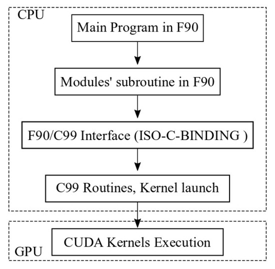
Figure 2.
Command chain scheme for the CPU–GPU solver.
In order to minimize inefficiencies due to memory transfers between the CPU and GPU, field arrays for velocity, pressure, and other physical magnitudes, as well as mesh geometrical properties, are permanently stored at the GPU global memory, even at the expense of intense GPU RAM utilization. Currently, about 1 GB of RAM is required for every 1.5 million cells in a typical simulation. Full field arrays are only transferred between the CPU and GPU at the beginning of the simulation and before writing intermediate or final output to disk. For this purpose, a copy of those fields is also permanently stored in CPU memory, which enables the overlap of disk latency with ongoing computations. MPI communications between nodes are overlapped with computations in a similar way, incorporating buffer arrays at the GPU and buffer transfer functions between the CPU and GPU, while keeping the original Fortran 90 implementation of the MPI communications [25]. Upgrading the communication scheme to handle direct communication between GPUs is planned for a future release of the software.
To promote coalesced memory access and prevent excessive need of atomic functions in several routines across the solver, a red-black scheme is adopted to store structured grid field arrays in GPU global memory. This strategy suits most of the solver routines well, as well as even simple linear solvers that can be optionally used in caffa3d.MBRi, like the Red-Black solver. Within these GPU arrays, data items are arranged in strips of one warp size length, alternating red-colored cells in one warp and black-colored cells in the following, after the arrays are first copied from the CPU to the GPU. This process is reverted before copying the arrays back to the CPU for output. Multidimensional arrays, as for velocity and position, are stripped along the relevant dimensions, so that each warp size strip holds same color and the same dimension data, with successive dimensions following one another in two warp size strips.
However, the most efficient linear solver included in caffa3d.MBRi for the heptadiagonal matrices arising from the structured grid scheme is the SIP Solver [34], for which the red-black scheme is not suitable due to the forward and backward substitution phases of the solver. Thus, a special memory scheme was adopted for the SIP solver routine according to the hyper-planes strategy. For details on this approach, please see [34].
With this in mind, the final structure of the GPU-using solver is depicted in Figure 3, where the execution order is shown and the commands and data transfer between the CPU and the GPU are presented. It is worth mentioning that within the solver block mentioned in Figure 3, one can find the computations needed for solving the aforementioned equations; nonetheless, the commands that order such executions as the outer iteration loop are controlled from the CPU.
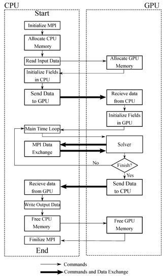
Figure 3.
Working scheme for the GPU-using solver.
2.2. Tracer Module
In order to handle the information needed to compute the pollutant dispersion, a module was incorporated into the original solver. This module is in charge of initializing the fields to be used as passive scalars and computing the boundary conditions and sources in the domain for those tracers. These last procedures are done by independent loops that are called on every timestep to compute three different kinds of emissions for each tracer, point, linear, or superficial source.
Firstly, the point sources correspond to commercial or industrial chimneys to be found in the domain; secondly, the linear sources represent vehicular emissions along the streets; finally, the superficial sources include domestic heating emissions, and represent them as a surface above the residential area of the domain. Given that all of these sources are defined geometrically, the way to compute the source terms on each cell is by checking whether that cell fulfills certain position requirements, so a loop through every cell is done on every timestep to compute the corresponding source term for each cell.
Taking into account the fact that the new code replaces the use of loops with GPU kernel routines, several changes had to be made to the original module. First of all, it had to be rearranged so that every loop was contained in its own subroutine, allowing the choice of whether to use serial computation in the CPUs or to use the GPUs. Every time a subroutine is to be called, two roads can be taken: One basically follows the original code, while the other calls a C99 function that will send a command to the GPU to execute what is called a Kernel. Each Kernel will correspond to a loop through the cells, with the Kernels being executed by several processors at the same time; each of them is in charge of a small set of cells, in comparison with the total amount of cells.
Next, the Kernels developed will be explained, but first, the original subroutines have to be explained. The loop that determines which cells will emit due to a point source consists of checking whether each cell’s center is inside a sphere centered in the chimney to be modeled with a predefined diameter. Moreover, the total volume of the emitting cells is needed in order to assign a source term to each of them, so at the initialization, a loop checking which cell will be emitting for each source and the total volume of each source (equal to the sum of the emitting cells volume for a certain source) is run, and the data is saved. Once this is done, an integer field called Point Emission Flag (PEF) gets a value for each cell of the domain; the idea is that the integer number will indicate which sources are emitting in that cell. In order to accomplish this, the field is computed in the following way every time the cell should emit due to the source number “SN”:
Once PEF is determined, it can be converted into a binary number that indicates which sources will be emitting through a cell, since each position of the binary number will correspond to a specific source; therefore, a 1 in the position of a certain source will indicate that the cell emits due to that source, while a 0 indicates that it is not emitting from that source. Given that one already has the PEF, the way to compute the source terms for the scalar transport is fairly simple; one has to loop through each point source and check whether each cell emits or not, and if it does, one has to assign the corresponding source term to it. In order to accomplish this using GPUs, the C99 function in charge of sending the Kernel command has to send the needed information to the device; this information includes fields, grid data pointers, and any extra value that is not saved in the device memory.
With this in mind, the Kernel in charge of computing the point sources will assign eight cells to every processor as the hyper-plane strategy and a Red-Black scheme are used, so the first part of each Kernel will be in charge of determining the cells’ indexes. Once this is done, a loop through those eight cells is done, so as to perform the needed computations for each cell. These computations include looping through the different point sources to determine if the cell has an emission associated with that source by using the PEF field; if it does emit, a source term is computed for that specific cell.
Similarly, the linear sources are computed the same way, as the emission of a cell depends whether it is inside a predefined prism or not, so a Linear Emission Flag (LEF) field is used, and the Kernel scheme is basically the same one. However, when computing the superficial sources, another scheme is needed, as the emitting cells will be those whose centers are inside a horizontal polygon and whose heights are just above a certain height. Taking this into account, each Kernel will be in charge of two columns of cells, as the hyper-plane strategy is not used, yet the Red-Black scheme is. So, after determining some indexes, a loop through the superficial sources is done, and the first cell above the pre-established height is determined for each column. Then, the position of the cell is computed and checked to see if it should emit or not; in case it does, the source term is assigned to that cell.
Apart from the passage of the previously explained subroutines, another module that computes statistical data was incorporated into the GPU scheme. The purpose of the module is to compute mean fields through the simulation by updating them on every timestep. With this in mind, a Kernel in charge of doing so was created with a scheme very similar to the one described for the point sources, but the computations done consist only of the update of a mean field defined by the input given. Using only one Kernel, one can to compute the mean field of as many fields as needed; for instance, mean velocity and mean tracer concentration fields are computed, among others.
3. Study Case
In order to test and compare the performance of the new code, a real life domain was considered, consisting of the surroundings of a power plant near Montevideo’s port area. Inside the domain, point and linear sources can be found; however, as no residencies are included in the area, superficial emissions were not included. Nonetheless, the proper operation of the new model for those emissions was tested and proved to work as expected. In the selected domain, the structures present were represented by the Immersed Boundary Method [28], a model that was already operating in the heterogeneous version of the solver. Once the domain was determined, the simulations were run with a timestep of one second.
In order to ensure an accurate representation of the pollutant dispersion, 5000 timesteps were run without any emission so as to let the flow develop. Then, the emissions were turned on, and 10,000 timesteps were simulated to ensure the concentration field reached stationary-like conditions. Last but not least, the mean concentration fields were computed over 20,000 more timesteps. In total, 35,000 s were simulated, printing information every 1000 timesteps, allowing the comparison of the performance of each solver when computing not only the velocity fields, but also the pollutant fields, as well as the mean fields for all magnitudes.
The simulated domain was a prism, decomposed into 20 blocks, each of them being a prism of made out of cells (including the boundary cells), leading to a total of 8,028,160 cells. Furthermore, an exponential growing height in the vertical direction was applied to the cells to ensure a proper representation of the flow near the floor, with an initial height for the bottom cells of 0.1 m. Given the fact that the solver will solve the speed for three directions and the pressure for the flow, and solve dispersion for four tracers, each cell will have eight degrees of freedom (DOFs), resulting in 59,043,840 DOFs for the entire simulation. In Figure 4, the domain and its block separation can be seen from above, while in Figure 5, it can be seen from a 3D perspective. In both Figures, the power plant present in the domain can be seen in grey.
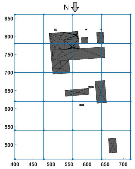
Figure 4.
Simulation domain seen from above. Black structure is the representation of the present structure.
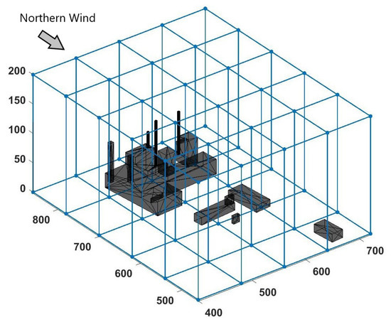
Figure 5.
Simulation domain isometric view. The black structure is the representation of the present structure.
Once the domain was determined, a Northern wind condition was imposed as the inlet condition. Additionally, one point source and two linear sources were configured as the pollutant emissions. In Figure 6, the emitting cells for the point source are shown in red in the left image, while the emitting cells that correspond to the linear sources are colored in the right picture.

Figure 6.
(a) Emitting cells in red for the point sources; (b) linear sources emitting cells inside the domain.
In order to compare the efficiency of the solvers, different platforms and configurations were used. The main one is a cluster made out of several nodes, each consisting of two CPUs (Intel Xeon Gold 6138 CPU @ 2.00 GHz) and a GPU (Nvidia P100) that counts with 3584 cores; this platform is called ClusterUy. Apart from it, another computer (Medusa) with a CPU (Intel(R) Core(TM) i7-6700K CPU @ 4.00 GHz) and four GPUs (Nvidia GTX 980 TI) with 2048 cores each were used. Given that ClusterUy is a shared platform, some parts of the simulations were run with shared nodes, especially for the CPU-based solver, reaching varying simulation times due to sharing memory with other processes. To avoid this problem, exclusive nodes were required to ensure each simulation was run without sharing memory with other processes.
Taking the different platforms into account, different simulations were performed, considering not only the platform and solver, but also the number of regions defined. For CPU-only simulations, each region is assigned to one CPU core, while for the Heterogeneous Computing solver, each region is assigned to an entire GPU, and all of its cores are used. Given that the domain and number of cells were never changed, only strong speed-up analysis was performed, leaving weak-scaling speed-up analysis for future research. In Table 1, the different simulations run are shown with their corresponding information.

Table 1.
Simulations run for each solver with their configurations and platforms.
Once the simulations were run, different execution times were considered: First of all, various running times were measured inside the Main Time Loop for the simulations run in ClusterUy, obtaining information about the execution time of a single timestep, the outer iterations loop inside one timestep, the momentum computation and tracers computations executed in one iteration, and lastly, the whole Main Time Loop. These measures were taken over 500 timesteps for every region in each simulation, thus obtaining a mean execution time for each run.
Apart from these measures, printing time between the two outputs was also measured in minutes to obtain an idea of the speed-up of the entire program, including reading and writing processes. The outputs in these measures were written every 1000 timesteps, and the resulting running times were also computed as the mean values for every simulation run.
4. Results
Once the module was implemented in the new solver, different simulations were run in order to ensure the proper representation of the different sources in the domain. Later on, a full-scale simulation for the study case described previously was run, reaching the following results for the concentration fields.
First of all, in Figure 7, the instant concentration for SO at a height of 60 m above the ground, computed by both solvers, is presented.
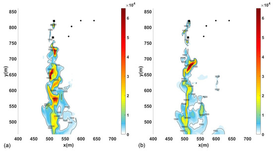
Figure 7.
SO instant concentration (g/m) at 60 m above ground (10 m below emission). (a) Results obtained with caffa3d, and (b) with the GPU-using version.
In Figure 7, the concentration peaks can be found in the different vortices generated by the structure represented by the Immersed Boundary Method and depicted in black in the Figure. In the right picture, the concentration for the CPU–GPU solver is shown; it can be seen that despite the different location of the peaks, they reach similar values of concentration. This difference in the location and distribution of the vortices is expected, as it is known that the parallelization of the scalar product leads to different numerical results in contrast to a sequential scalar product, due to rounding errors [20]. These differences in results are then increased because of the turbulence present in the simulations, resulting in different velocity fields and different concentration fields. Nonetheless, the results reached are within what is expected, representing different turbulent conditions of the same flow.
In order to have a better comparison of the results, the mean concentration fields are compared in Figure 8, where the CO mean concentration field at ground level is shown for the CPU and CPU–GPU solvers.
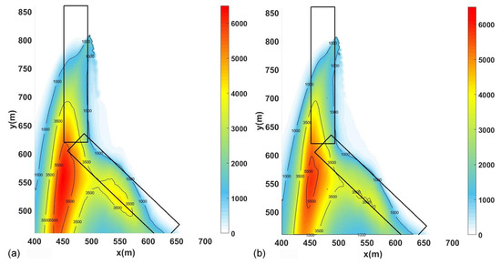
Figure 8.
mean concentration (g/m) at ground level, (a) results obtained with caffa3d, and (b) with the GPU-using version.
As expected, the mean concentration fields are smoother than the instant ones, and are not dependent on the vortices generated by the structure. Therefore, as Figure 8 shows, the mean concentration fields are very similar, especially in defining the impact zone of the emissions simulated, as expected. It can be concluded that the new solver reaches consistent results in comparison with the original solver, proving to be a reliable code when representing the physics involved in the present problem.
Once the results from both solvers were found coherent, performance was analyzed. First of all, the different execution times for parts of the code were compared for every 500 timesteps run, and results are shown in Table 2.

Table 2.
Computation time in seconds for different procedures of the code (only ClusterUy simulations).
In order to have a better comparison of the results, the speed-up for every procedure was computed against the simulation with four regions run with the CPU-only solver, providing the results shown in Figure 9.
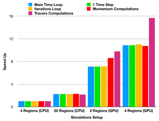
Figure 9.
Speed-ups for different procedures for simulations run in ClusterUy.
Figure 9 shows the important speed-ups that are achieved when GPUs are implemented, even when fewer regions are defined. Furthermore, it can be appreciated that Tracer Computations have the largest speed-up when using GPUs, indicating that the migration of the model was worth it, reaching speed-ups of over 15 times.
Apart from this analysis, the computation time needed for 1000 timestep was considered, only for when all of the fields and their mean values were being computed, which corresponds to the computations done after the 15,000 first timesteps. Moreover, only the results when computing in an exclusive node were considered, as high variability in simulation times was found when sharing nodes in ClusterUy. In Table 3, the computation times for the different simulations and their configurations are shown.

Table 3.
Computation times (minutes) for computing 1000 timesteps of the simulation.
As Table 3 shows, the new solver as a whole works faster than the original, having a speed-up of up to 8.5 times when using the same domain decomposition. Furthermore, an improvement of up to four times is reached when using five times fewer processors with the GP-using version, and even a speed-up of three times when using 10 times fewer processors. Taking into account the fact that using half the GPUs slows the simulation by around only 30% indicates that the GPUs were not being fully used, so even bigger domains could be simulated with little change in the simulation time for the heterogeneous version, while the original solver, due to its serial nature, would be slowed down when computing bigger domains.
When comparing these results against the Main Time Loop speed-up shown before, the speed-ups for the whole program are lower. This can be explained mainly by the fact that the Main Time Loop does not include the output writing and other procedures handled by the CPU in both versions; however, a possibility to write the output files while continuing computing on the GPU is being taken into account so as to reach higher speed-ups for the whole code.
Apart from these analyses, the amount of time spent on data transfer was obtained with a profiler for a smaller simulation with only one region (no MPI communication), finding that only of the total time was spent on exchanging data between the CPU and GPU. It is worth mentioning that this mostly accounts for the initial data transfer between the host and the device, since it accounts for of the total time, while the other of the total time was spent on transferring data from the GPU back to the CPU. Even though these results are not directly relatable with the study case, they do show that data transfer between the GPU and the CPU accounts for a small percentage of time when the initialization exchange is not taken into account, enabling further improvements, as this exchange does not limit the parallelization.
5. Conclusions
As far as the module implemented in the new solver is concerned, the results obtained were coherent with the ones obtained from the original solver. Furthermore, as caffa3d.MBRi has been validated in some pollution study cases [25,33], the new engine proves to be a reliable tool for the computation of pollution dispersion as well.
When computational performance is considered, an important improvement can be seen, as simulation times were reduced by at least eight times with the same decomposition, and even of three times when using ten times fewer processors. These results are highly promising, as they show not only that faster computations are possible, but also that bigger domains with higher resolutions are possible as well, since only two cores were used for some simulations and little difference in computation time was noticed.
In conclusion, the migration of the model was successful, contributing to the development of a general purpose CFD open-source code that allows computations to be done either on CPUs or GPUs. Moreover, this study presents the improvements reached by the incorporation of the HPC techniques described, encouraging the use of this method on simulations that require high computational power due to the domain size, as is the case of pollution dispersion in urban environments, leading to important time and resource reductions. These reductions could enable the use of this kind of software as a real-time simulator, allowing the user to predict pollutant dispersions as soon as an incident occurs. Furthermore, due to the high variability of the flows involved, further statistical analysis could be easily performed to forecast and diagnose air quality in urban environments, achieving stronger results which can then be used for city design, health risk prevention, emissions control, etc.
Taking into account the promising results obtained from the new Heterogeneous Computing solver, more capabilities are expected to be migrated from the original solver. Some of them are Wind Turbine models, VOF models, and other multiphase flow models, among others. Moreover, when it comes to the emission sources, modeling the possibility of including moving sources is being taken into account so as to represent the vehicular emission explicitly.
Author Contributions
Conceptualization, G.U., M.M., and G.F.; methodology, G.F. and G.U.; software, G.U. and G.F.; formal analysis, G.F.; writing—original draft preparation, G.F.; writing—review and editing, G.F., M.M., and G.U.; supervision, G.U and M.M.; project administration, M.M. and G.U. All authors have read and agreed to the published version of the manuscript.
Funding
This research was funded partly by ANII’s project FSE-1-2014-1-102535: “Modelo integral de emisiones gaseosas y particuladas a la atmósfera: Análisis de una zona industrial y residencial de Montevideo”, and partly by the Academic Postgraduate Commission (CAP) by funding the Master’s degree scholarship through which this study was performed.
Conflicts of Interest
The authors declare no conflict of interest.
Abbreviations
The following abbreviations are used in this manuscript:
| CPU | Central Processing Unit |
| Heterogeneous Computing GPU | Graphic Processing Unit |
| CFD | Computational Fluid Dynamics |
| HPC | High Performance Computing |
| SPMD | Single Program – Multiple Data |
| SIP | Strongly Implicit Procedure |
| CUDA | Compute Unified Device Architecture |
| MPI | Message Passing Interface |
| VOF | Volume Of Fluid |
| PEF | Point Emission Flag |
| LEF | Linear Emission Flag |
| DOFs | Degrees Of Freedom |
References
- Chio, C.P. Assesing vanadium and arsenic exposure of people living near a petrochemical complex with two-stage dispersion models. J. Hazard. Mater. 2014, 271, 98–107. [Google Scholar] [CrossRef] [PubMed]
- Sarigiannis, D.A. Total exposure to airborne particulate matter in cities: The effect of biomass combustion. Sci. Total. Environ. 2014, 493, 795–805. [Google Scholar] [CrossRef] [PubMed]
- Vardoulakis, S. Modelling air quality in streets canyons: A review. Atmos. Environ. 2003, 37, 155–182. [Google Scholar] [CrossRef]
- Cheng, X. Numerical studies on flow fields around buildings in a street canyon and cross-road. Adv. Atmos. Sci. 2005, 22, 290–299. [Google Scholar]
- Colvile, R.N. The transport sector as a source of air pollution. Atmos. Environ. 2001, 35, 1537–1565. [Google Scholar] [CrossRef]
- Lateb, M. On the use of numerical modelling for near-field pollutant dispersion in urban environments—A review. Environ. Pollut. 2016, 208, 271–283. [Google Scholar] [CrossRef]
- Toparlar, Y. A review on the CFD analysis of urban microclimate. Renew. Sustain. Energy Rev. 2017, 80, 1613–1640. [Google Scholar] [CrossRef]
- Pullen, J. A comparison of contaminant plume statistics from a Guassian puff and urban CFD model for two large cities. Atmos. Environ. 2005, 39, 1049–1068. [Google Scholar] [CrossRef]
- Riddle, A. Comparison between FLUENT and ADMS for atmospheric dispersion modelling. Atmos. Environ. 2004, 38, 1029–1038. [Google Scholar] [CrossRef]
- Kirk, D.; Hwu, W. Programming Massively Parallel Processors: A Hands-on Approach; Morgan Kaufmann: Burlington, MA, USA, 2010. [Google Scholar]
- Owens, J.D. A Survey of General-Purpose Computation on Graphics Hardware. Comput. Graph. Forum 2007, 26, 80–113. [Google Scholar] [CrossRef]
- Barrachina, S. Exploiting the capabilities of modern GPUs for dense matrix computations. Concurr. Comput. Pract. Exp. 2009, 21, 2457–2477. [Google Scholar] [CrossRef]
- Ezzatti, P. Using graphics processors to accelerate the computation of the matrix inverse. J. Supercomput. 2011, 58, 429–437. [Google Scholar] [CrossRef]
- Afzal, A. Parallelization Strategies for Computational Fluid Dynamics Software: State of the Art Review. Arch. Comput. Methods Eng. 2017, 24, 337–363. [Google Scholar] [CrossRef]
- Fan, Z. GPU Cluster for High Performance Computing. In Proceedings of the 2004 ACM/IEEE Conference on Supercomputing, Pittsburgh, PA, USA, 6–12 November 2004; pp. 47–59. [Google Scholar]
- Valero-Lara, P. Accelerating Solid-Fluid Interaction using Lattice-Boltzmann and Immersed Boundary Coupled Simulations on Heterogeneous Platforms. Procedia Comput. Sci. 2014, 29, 50–61. [Google Scholar] [CrossRef]
- Valero-Lara, P. Accelerating solid–fluid interaction based on the immersed boundary method on multicore and GPU architectures. J. Supercomput. 2014, 70, 799–815. [Google Scholar] [CrossRef]
- Valero-Lara, P. Accelerating fluid–solid simulations (Lattice-Boltzmann and Immersed-Boundary) on heterogeneous architectures. J. Comput. Sci. 2015, 10, 249–261. [Google Scholar] [CrossRef]
- Valero-Lara, P. Multi-Domain Grid Refinement for Lattice-Boltzmann Simulations on Heterogeneous Platforms. In Proceedings of the 2015 IEEE 18th International Conference on Computational Science and Engineering, Porto, Portugal, 21–23 October 2015; pp. 1–8. [Google Scholar]
- Griebel, M. A multi-GPU accelerated solver for the three-dimensional two-phase incompressible Navier-Stokes equations. Comput. Sci. Res. Dev. 2010, 25, 65–73. [Google Scholar] [CrossRef]
- Thibault, J.; Senocak, I. CUDA Implementation of a Navier-Stokes Solver on Multi-GPU Desktop Platforms for Incompressible Flows. In Proceedings of the 47th AIAA Aerospace Sciences Meeting Including the New Horizons Forum and Aerospace Exposition, Orlando, FL, USA, 5–8 January 2009. [Google Scholar]
- Zhu, X. AFiD-GPU: A versatile Navier-Stokes Solver for Wall-Bounded Turbulent Flows on GPU Clusters. Comput. Phys. Commun. 2017, 229, 199–210. [Google Scholar] [CrossRef]
- Emelyanoz, V.N. Development of Advanced Computational Fluid Dynamics Tools and their Application to Simulation of Internal Turbulent Flows. Prog. Flight Phys. 2015, 7, 247–268. [Google Scholar]
- Usera, G. A parallel block-structured finite volume method for flows in complex geometries with sliding interfaces. Flow Turbul. Combust. 2008, 81, 471–495. [Google Scholar] [CrossRef]
- Mendina, M. A general purpose parallel block-structured open source incompressible flow solver. Clust. Comput. 2014, 17, 231–241. [Google Scholar] [CrossRef]
- Igounet, P. GPU Acceleration of the caffa3d.MB Model. In Proceedings of the Computational Science and Its Applications—ICCSA 2012, Salvador de Bahia, Brazil, 18–21 June 2012; pp. 530–542. [Google Scholar]
- Ferziger, J.; Peric, M. Computational Methods for Fluid Dynamics; Springer: Berlin, Germany, 2002. [Google Scholar]
- Liao, c. Simulating flows with moving rigid boundary using immersed-boundary method. Comput. Fluids 2010, 39, 152–167. [Google Scholar] [CrossRef]
- Lilek, Z. An implicit finite volume method using nonmatching block structured grid. Numer. Heat Transf. 1997, 32 Pt B, 385–401. [Google Scholar] [CrossRef]
- Lange, C.F. Local block refinement with a multigrid solver. Int. J. Numer. Methods Fluids 2002, 38, 21–41. [Google Scholar] [CrossRef]
- Draper, M. A Large Eddy Simulation Actuator Line Model framework to simulate a scaled wind energy facility and its application. J. Wind Eng. Ind. Aerodyn. 2018, 182, 146–159. [Google Scholar] [CrossRef]
- Steinman, D. Variability of CFD Solutions for Pressure and Flow in a Giant Aneurysm: The SBC2012 CFD Challenge. J. Biomech. Eng. 2018, 135. [Google Scholar] [CrossRef]
- Fernández, G. Numerical Simulation of atmospheric pollutants dispersion in an urban environment. In Proceedings of the Tenth International Conference on Computational Fluid Dynamics, Barcelona, Spain, 9–13 July 2018. [Google Scholar]
- Ezzati, P. Towards a Finite Volume model on a many-core platform. Int. J. High Perform. Syst. Archit. 2012, 4, 78–88. [Google Scholar]
© 2020 by the authors. Licensee MDPI, Basel, Switzerland. This article is an open access article distributed under the terms and conditions of the Creative Commons Attribution (CC BY) license (http://creativecommons.org/licenses/by/4.0/).