Abstract
As a result of the growing demand for highly customized and individual products, companies need to enable flexible and intelligent manufacturing. Cyber-physical production systems (CPPS) will act autonomously in the future in an interlinked production and enable such flexibility. However, German mid-sized plant manufacturers rarely use virtual technologies for design and validation in order to design CPPS. The research project Virtual Commissioning with Smart Hybrid Prototyping (VIB-SHP) investigated the usage of virtual technologies for manufacturing systems and CPPS design. Aspects of asynchronous communicating, intelligent- and autonomous-acting production equipment in an immersive validation environment, have been investigated. To enable manufacturing system designers to validate CPPS, a software framework for virtual prototyping has been developed. A mechatronic construction kit for production system design integrates discipline-specific models and manages them in a product lifecycle management (PLM) solution. With this construction kit manufacturing designers are able to apply virtual technologies and the validation of communication processes with the help of behavior models. The presented approach resolves the sequential design process for the development of mechanical, electrical, and software elements and ensures the consistency of these models. With the help of a bill of material (BOM)- and signal-based alignment of the discipline-specific models in an integrated mechatronic product model, the communication of the design status and changes are improved. The re-use of already-specified and -designed modules enable quick behavior modeling, code evaluation, as well as interaction with the virtualized assembly system in an immersive environment.
1. Introduction
The fourth industrial revolution announced as Industrie 4.0 will enable a more flexible usage of production resources. The production of smaller batch sizes, up to sizes that are individually matched to customer needs, will be realized by autonomous interacting production systems. These autonomous production systems should be intelligent and interlinked with other production systems, as well as the production-IT. For this reason, physical functions are combined with software features to a cyber-physical system (CPS) [1]. In the context of production, several interacting CPS comprise a cyber-physical production system (CPPS) [2,3].
In addition to the development and integration of flexible hardware (e.g., flexible grippers, handling systems), additional logic behavior and communication mechanisms must be designed. Therefore, CPPS need to be integrated into the production-IT, as well as in global information networks [4]. This integration needs to be considered during the development, as well as in the overall manufacturing system validation.
For designing and validating CPPS, various approaches have been presented [5,6,7]. However, they assume a completely new design of systems incorporating microcontrollers, such as field programmable gate arrays (FPGA) or other embedded system controllers. The hardware-oriented design and physical integration in the mechatronic product design seems to be different from the software oriented “dematerialization” of CPS design [8]. Behavior modeling has been proposed by [9] as a possible solution for industrial practice, but emphasizes that the current heterogeneous and isolated tools lack interfaces for data exchange and simulation.
The German plant manufacturers are often mid-sized companies with mechanic-centered development approaches and a sequential design process for mechanics, electrics, and software [10]. Virtual technologies, especially for mechatronic design and validation, such as virtual commissioning, are only applied in complex projects, e.g., automotive body in white area [11]. In order to handle the challenge of transforming mechatronic designs into a CPPS design [12], the publicly-funded project Virtual Commissioning with Smart Hybrid Prototyping (VIB-SHP) investigated the usage of virtual technologies in production system design. The development process was extended with the necessary design and validation steps of communication processes for interlinked and autonomous production.
This paper provides an overview of existing design approaches and the general usage of virtual technologies in mechatronic product design. Additionally, the possible usage of virtual technologies for assembly systems design is presented. Based on the identified techniques a software framework for CPPS design and validation is proposed to enable plant manufacturers to apply these virtual techniques. Finally, the modular design of functional units are presented with the help of a manufacturing system construction kit including behavior models.
2. State of the Art in Mechatronic Product Validation/Manufacturing System Validation
For the design and validation of manufacturing systems and their processes (e.g., robot planning and validation), today’s PLM vendors offer simulation environments, such as Dassault Systèmes DELMIA or SIEMENS PLM Process Designer and Process Simulate. These planning and simulation applications offer high-end capabilities for planning and validation of complex manufacturing systems, but require the usage of the whole PLM toolset of a vendor. For a smooth and efficient usage, the linked computer aided design (CAD) systems, as well as the linked PLM solution, are recommended.
However, such simulation tools do not match the requirements of mid-sized plant manufacturers in Germany: Firstly, the companies use dedicated CAD tools which may differ from the CAD tools of mentioned PLM toolsets. Secondly, they do not have the know-how to use these monolithic design and simulation environments. Thirdly, the necessary integration of design results in the simulation models is time-consuming. Therefore, these simulation tools focus more on large companies which fulfill their complete product development and production planning by using PLM toolsets. For the usage of these PLM toolsets in the mid-size company context, the manual model definition and update processes, as well as geometry converter processes, are not an option. Today, design applications provide open interfaces and application programming interfaces (APIs) [13], while integrated data management is missing.
From the point of view of a design method, mechatronic design approaches, such as the “V-model” [14] and the “extended V-model” (V-model-XT, cf. [15]), as well as other design approaches, are given, however, they are often defined as too academic for the practical application in industry [16] or do not address the existing roles in company organizations [17]. For the manufacturing system design, a model-based engineering V-model considering the modularization of components, subsystems (stations), as well as the complete system is proposed (Figure 1).
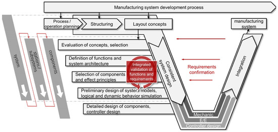
Figure 1.
Adapted V-model for manufacturing system design.
The small and mid-sized enterprises (SME) plant manufacturers involved in the research project VIB-SHP criticized the absence of an overview regarding virtual technologies and their capability for verification and validation that can be applied during design. Therefore, several workshops with these plant manufacturers have been conducted. Validation in product development ranges from detailed physical prototypes—physical mock ups (PMU)—to virtual validation with virtual prototypes. Consequently, diverse computer aided engineering (CAE) methods are used, e.g., finite element methods (FEM) or spatial analysis with digital mock-ups (DMU). These virtual technologies comprise different virtual prototypes and environments, e.g., [18]:
- Functional digital mock-up (FDMU): Research is going on in order to extend DMU with functional elements to FDMU. Thus, the mechatronic aspect as behavior and programming must be integrated as well, e.g., Dassault Systèmes RFLP-concept (requirements, functions, logic, and physics) within CATIA V6 [19].
- Virtual reality and augmented reality: VR is a technology to enable high-end visualization of digital models. The main idea is to provide an immersive and interactive environment to increase the emergence of future products. The projection can be realized by different forms (e.g., CAVE, Cave Automatic Virtual Environment). The overlaying of virtual components, e.g., information, on a physical component is known as augmented reality.
- Smart hybrid prototyping (SHP): SHP basically enables digital models to interact with physical prototypes in VR and, consequently, provide a realistic experience of virtual models. Therefore, a mixed reality environment expands the validation and verification of FDMUs [20].
For specific design activities in engineering, e.g., dynamic behavior simulations, numerical simulations such as MATLAB or Simulink, are also used to investigate specific design aspects [21,22]. For the manufacturing system design, physics, and automation behavior simulations with Simulink have been integrated in a software framework [23], but seem to be too detailed in terms of simulation depth and simulation targets required by the plant manufacturers.
One important finding within the workshops with the plant manufacturers and researchers of the VIB-SHP project was that virtual technologies provide potent means in order to develop and test CPS and CPPS by integrating product, software, and electronics in a virtual prototype. Nevertheless, feasibility and the cost-benefit ratio need to be analyzed in the context of small and mid-sized enterprises (SME).
3. Usage of Virtual Technologies within Manufacturing Systems Design
Today, complexity in programmable logic controller (PLC) design, especially at automotive OEMs in the “body in white” area, is solved with the technology of virtual commissioning [11]. By virtualizing all integrated automation components, their peripherals and fieldbus communication, a holistic test of the controller code development is possible. Due to the need to support PLC design and validation, virtual commissioning has been identified as one of the virtual technologies to be integrated in the development process of CPPS.
Virtual reality (VR) is often used for design reviews in order to validate geometric models in a digital mock-up (DMU) model. Functional aspects are usually not in the scope of such models. For the alignment of the mechanical, electrical, and controller design, the functional validation of a virtual prototype was identified by plant manufacturers as an additional virtual technique. In a VR session the designed geometry, including their kinematic and automation behavior, as well as the PLC design (including the electrical and pneumatic wiring) in interaction can be validated. Therefore, VR was identified as gainful for the alignment of the discipline-specific design. The possibilities and benefits of VR for production system design have already been identified by research and industry [24].
In addition to the functional prototype in a VR session the Chair of Industrial Information Technology of the Technische Universität Berlin has developed the technology “smart hybrid prototyping” (SHP) for product evaluation and optimization [20]. With the help of physical behavior simulation, special haptic devices with force feedback and VR visualization, as well as product functionalities, can be explored based on the haptic experience with high immersion. In assembly, the system design of manual operations—for loading, or the assembly itself—has still to be considered. The interaction with the assembly process and corresponding validation was, therefore, identified as the use case.
Due to the need of expert knowledge for the application of the virtual technologies listed in Section 2, the use of a mechatronic construction kit for production systems has been proposed. The construction kit includes behavior models besides electrical models, mechanical models, and software (PLC) modules. With the help of the construction kit, planners are able to quickly build up a virtual prototype. The geometry, kinematic, electrical, and behavior models are linked in construction kit modules with the design concepts and can be used without further modeling effort. This kit is supposed to simplify/facilitate the usage of virtual technologies by providing the related models for already-detailed modules. With this approach, the transformation of German plant manufacturers from mechanic- to controller-centered design is enabled.
The communication with other manufacturing systems, as well as their integration in the production-IT, has been identified as additional design and validation tasks. In order to enable plant manufacturers to cope with the production-IT integration, specific modules with generic functions for supervisory control and data acquisition (SCADA)- and manufacturing execution systems (MES)-integration are provided by the construction kit. These production-IT-relevant modules need to be adapted according to specifications of the customer and enable the preliminary SCADA- and MES-integration without the presence of the real systems. Later in the design process of the PLC, the test systems of the customers can be connected with the controller of the virtual prototype for a final integration test.
The identified usage of virtual technologies and the mechatronic construction kit during the development process are shown in Figure 2.
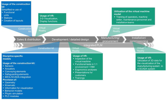
Figure 2.
Virtual technologies and usage of the construction kit within the product development process of an assembly system.
An added value for the use of VR for German mid-sized plant manufacturers is given in the early phase: during the concept phase, designers are enabled to generate a functional, virtual 3D-prototype for layout evaluation, assembly function allocation for assembly stations, and material flow validation. The construction kit provides functional groups or complete stations of an assembly system, including kinematics and behavior models.
During the design process, the validated and proven modules developed within the construction kit can be re-used. Consequently, the involvement of automation experts and PLC programmers is reduced for detail engineering. With the help of already-detailed modules, only their logical integration is necessary. A design of the assembly system “from scratch” can be avoided. Knowledge and “best practices” in the electrical and PLC design are provided to designers with the detailed modules. By means of the construction kit, virtual prototyping of assembly systems can be simplified. Additionally, new variants can be set up quickly by composing the modules of the construction kit. For design reviews, the developers are able to validate their discipline-specific design with the help of behavior models. In the case of mid-sized plant manufacturers, a higher degree of re-use of their designs should be ensured and engineering efforts reduced.
The involved German mid-sized plant manufacturers also reported a lack of availability of PLC-programmers. By using the virtual prototype, the PLC design, as well as the final PLC test during virtual commissioning, can be realized earlier. Additionally, the involvement of PLC programmers can be decoupled/disconnected from today’s sequential design process. Once the functional, virtual prototype has been aggregated by the modules, the future staff and operators can test the virtually-designed assembly system. After the testing (procedure), they can provide feedback and address change requests at an early stage. Moreover, by a frontloading PLC-design, the human machine interface (HMI) can be developed and validated earlier. With the SHP technology, the future assembly process can also be tested and validated.
4. Components of the Software Framework
For the interaction with a virtual prototype of a manufacturing system, not only visual, but also functional aspects, need to be combined in an interactive model. The purpose of the software framework architecture is to combine the mechanical design—including kinematics, automation, and physics behavior, as well as the PLC design in a simulation environment. German plant manufacturers, typical SME, have only limited access to resources to gain specific modeling knowledge and integrate new design and simulation tools in their IT landscape. In consequence, the integration of existing design applications into a software framework was another aspect to be considered in order to gain acceptance with mid-sized plant manufacturers. Therefore, the software framework is composed of an open simulation environment and a corresponding design data management.
Firstly, the virtualization of the automation component behavior, the fieldbus, the automation periphery, and production IT can be realized with a virtual commissioning application. After the virtualization, plant manufacturers are able to design and test communication processes on a real-time basis, as well as not time-critical communication processes of a CPPS, e.g., asynchronous fieldbus communication or communication via OPC. Secondly, the integration of the relevant models into an extended mechatronic data model enables plant manufacturers to test and validate mechanical-, electrical-, and PLC design with a virtual prototype. The behavior models create the link between discipline-specific designs and enable all involved developers to review their design in the context of the functional, virtual prototype. Designers can discuss issues and challenges during the alignment of discipline-specific designs. In addition, the CPPS design becomes immersive for all involved stakeholders at an early stage. Thirdly, the designers need support for the management of the discipline-specific models and the usage of the software framework. For this, a construction kit has been defined providing the involved designers with a consistent set of models and configuration information for the software framework.
4.1. Simulation Environment
In order to establish the necessary interaction between simulation applications and the visualization environment, the open source TUI framework (tangible user interface) [25] is used for signal exchange. For the TUI framework, several interfaces are available and have been developed by other institutions, universities, and research organizations. The components of the presented software framework (Figure 3) have been defined together with several software-solution developers involved in the research project VIB-SHP. For automation behavior simulation, the virtual commissioning system “WinMOD” has been selected within this research project, while for physical behavior simulation, the “Mechatronic Concept Designer” (MCD) of SIEMENS PLM has been selected. Other physical behavior simulation systems, like DYMOLA or MATLAB, can be connected to the TUI-framework via an OPC interface. The automation virtualization and behavior simulation application WinMOD allows the designer to connect different fieldbus types, also in parallel-operated fieldbus types. For this reason, virtual, as well as real, PLC controllers can be connected to the automation behavior model. The signals for kinematics of the manufacturing system are transferred via the TUI framework and interlinked with the VR scene of the manufacturing system.
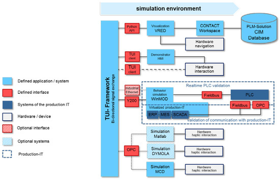
Figure 3.
Simulation environment of the software framework.
For realistic visualization the VR software of Autodesk VRED has been selected. For the integration of VRED, a Python API in the TUI framework has been developed regarding the manipulation of automation components according to their kinematics. In order to retrieve an up-to-date VR scene graph of mechanical design, the PLM solution “CIM-Database” stores native CAD data and provides lightweight Jupiter Tessellation (JT) data for the VR solution VRED. In addition, VRED allows several possibilities to visualize the scene graph, from a “desktop” visualization, CAVE- and power wall-visualization, up to mobile solutions, like the HTC Vive© or Oculus Rift©.
For the integration of the smart hybrid prototyping technology, a modular approach has been chosen. The physical behavior simulation is encapsulated together with the haptic devices. The only relevant interface regarding the simulation environment is the OPC interface of the TUI framework. In order to enable designers during design reviews to interact with the virtual prototype, an HMI application for the override of signals of the manufacturing system has been designed and connected to the TUI framework. The application also allows the designers to retrieve additional information about the used automation modules, e.g., the cost of the module during early design stages, or their current signal states during validation and failure identification in PLC design. Additionally, the demonstrator HMI allows an override of kinematic and controller signals for the manual control of the actors of the virtual prototype. In case of a missing PLC code, mechanical collisions can be investigated by manipulating kinematic functions. Moreover, sensor states can be set and signal errors, as well as fault situations, can be emulated.
With the usage of the open source TUI framework, not only the integrated applications, but also other design, simulation, and visualization applications, can be connected to the software framework for virtual prototyping. The openness of the simulation framework ought to give an opportunity to mid-sized plant manufacturers to use open source applications for interlinking design data and simulation applications to a functional, virtual prototype.
4.2. Extended Mechatronic Product Data Model and Multi-Discipline Construction Kit
To enable designers to use the proposed software framework, each functional module needs corresponding models for the integrated application. In addition, for each functional module configurations for WinMOD, for the TUI framework, the Python client, as well as the HMI application, need to be available. For an immersive visualization, VR shaders and accompanying environments for the VR scene can be linked to mechanical design.
In addition to the availability of models and framework component configurations, all designers need to work on a shared database and connect the design and modeling tools to the PLM solution (Figure 4).
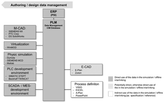
Figure 4.
Development applications connected to the PLM-solution.
With the presented design data management, the plant manufacturers are able to store their discipline-specific design into a shared database and group them to functional modules. Already-developed and verified functional units with a high degree of re-use, as well as a validated and verified design state, are linked to a module. In addition, identified procurement and cost information from a linked enterprise resource planning (ERP) system can be linked to a module. Moreover, the modules of the construction kit enclose the virtualization of the logic behavior in a WinMOD macro, fieldbus communication, and configuration information, as well as the visualization data for the usage in the software framework. The software design for MES and SCADA communication can also be stored in the data management solution and integrated in a module of the construction kit.
The consistency of the discipline-specific models and the linked behavior model within a functional module is ensured by the alignment of the bill of material (BOM), as well as by their signals: in the case of a modification, e.g., the change of a pneumatic actor, the link to the behavior model identifies the change in mechanical design and forces an update of the behavior model. The changes within a functional module, e.g., the integration of an additional sensor by a mechanical designer, automatically updates the signal list, as well as identify necessary changes of the fieldbus peripheral. With this approach, the functional modules with their discipline specific models and behavior model are aligned. Changes in mechanical, electrical, and PLC design can be evaluated within the simulation environment.
Consequently, a dedicated PLM item type has been defined for the functional modules covering the design and validation applications. For the manufacturing system itself, or a set of functional modules with their own PLC controller, a second item type (CPPS item type) was defined: the PLC-code (PLC project), as well as the automation behavior simulation project are additional elements, which need to be available for the CPPS test. The behavior simulation project, which reproduces the logical wiring, is mandatory for a manufacturing system or a set of functional modules with their own PLC controller. For virtual commissioning, each PLC controller must be linked to an instance of the behavior simulation. Wiring diagrams, as well as the VR scene setup for the design solution can also be stored within the CPPS item type. Both item types provide their protocols, as well as the variables for the communication with superior controllers, other CPPS, or linked SCADA and MES systems (Figure 5).
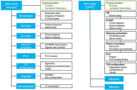
Figure 5.
Item structure for a manufacturing system and a module of the manufacturing system.
Both of the item types are provided by the PLM solution “CIM-Database”. In order to design a first draft of a manufacturing cell, the mechanical engineer can drag and drop needed modules in a CAD solution, thus creating a first layout variant. In a second step, the modules can be configured and linked according to the fieldbus configuration within the virtual commissioning software WinMOD. Finally, concept designers obtain a first layout and an executable virtual prototype by exchanging signal states between WinMOD and VRED via the TUI framework. Moreover, the designer can approximate the costs of the assembly system with the help of cost information provided by the construction kit. After completing the system design, all new module variants, cells, or even the complete system, can be stored as new modules.
For the design and validation of the communication between functional modules or manufacturing cells, a WinMOD communication module is provided. This communication module provided by the construction kit simulates the interaction and information exchange between modules or other manufacturing cells (Figure 6). After validation, the communication can be integrated in the PLC.
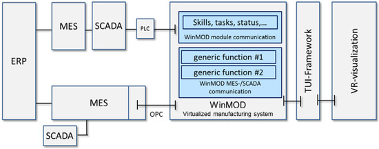
Figure 6.
WinMOD behavior model communication with decoupled SCADA and MES-entities and communication with interface modules.
For SCADA and MES integration, specific modules with generic functions according to ISA-95 have been defined for the construction kit. These functions ought to support the integrator of SCADA and MES entities by a modular definition of the production IT functions with dedicated WinMOD interface modules (Figure 6). The PLC developers and system integrators are enabled to develop in parallel SCADA and MES communication, as well as PLC design: both developers can decide the flexibly, at what time they want to merge both designs, while both WinMOD simulation projects can be used separately and independently during the design of the manufacturing system and PLC code. In practice, it is recommended that the customer or operator of the manufacturing system define a WinMOD interface in advance and provide a tested interface module to the PLC developer.
4.3. Scenario for Evaluation
For the validation of the proposed software framework and the usage of the mechatronic construction kit, an industrial use case has been defined under aspects of autonomous and interlinked production. The involved mid-sized plant manufacturers provided design data of already-designed assembly cells and already-designed conveyor belt components. Both provided assembly cells have been integrated as CPPS items (see Section 4.2) in the construction kit, while the conveyor belt components have been integrated as modules (see Section 4.2). For all components, abstracted behavior models were created with the help of the vendor of the virtual commissioning software WinMOD, as behavior modeling skills are not available at the plant manufacturers’ companies.
The plant manufacturers positioned the two already-designed assembly cells and composed a transport system from the provided modules in a 3D layout (Figure 7). Both assembly cells have been connected via the conveyor belt system with two levels of conveyors lying upon each other.
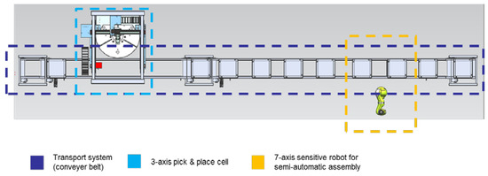
Figure 7.
Created 3D CAD layout and positioned systems with the construction kit for evaluation (bird-view).
All defined systems of the scenario will later communicate asynchronously with each other. A final assembly line at one end of the conveyer belt system (not part of the design) requests a variant of the assembled product. Within the scenario two types of reinforcements for two variants of cars are pre-assembled with noise vibration harnesses (NVH). Two process variants have been defined for a fully-automatic, as well as semi-automatic, assembly of the NVH parts.
The CAD tool SIEMENS NX 10.0 of a plant manufacturer was connected to the framework. The available modules and CPPS components have been added to the assembly line setup. As an example for a CPPS component, a seven-axis lightweight robot (KUKA LBR), including a gripper and controller, was detailed. As an example for an automation component, a lift station of the conveyor belt system was detailed (Figure 8). The design information, e.g., the signal list, fieldbus components, sensors, and drives were defined and modeled according to the schemes provided by the automation experts of the plant manufacturers. The presented motion profiles for the position of the lift and the conveyor belt velocity represent the real-time behavior of the lift’s kinematics behavior simulated by WinMOD. The signals for the kinematic of the conveyor belt lift were linked automatically in WinMOD via its Y200-interface to the TUI framework. A Python script in VRED continuously updates the VR scene with the signal value from the TUI framework with its kinematic movements.
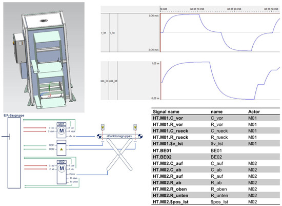
Figure 8.
CAD model, behavior model, schematic diagram, and signal list of a module of the construction kit (conveyor belt lift).
The design data for the modules (CAD model, electrical wiring, and behavior model) was integrated in the specified PLM item by connecting the design applications SIEMENS NX, ePlan, and WinMOD to the PLM solution CIM-Database. The different models were stored in the “workspace” of the PLM solution on the local disk of the designers. After updating one or more models during the design, the PLM solution CIM-Database identified the different model types by their extension. During the save operation, the PLM items were updated with the changed models and meta-information.
For realistic visualization (Figure 9), VR shaders have been linked to the designed CAD geometry. For this, the existing material library of the CAD solution NX has been linked to a VR shader library providing realistic visual effects and appearance according to the chosen material.
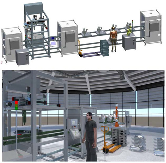
Figure 9.
CAD design data and realistic visualization in VR.
The behavior models of the used modules were linked according to the electrical wiring within the behavior simulation WinMOD. Moreover, the PLC-hardware configuration was defined and transferred to WinMOD according to the planned controller architecture. Two independently-controlled assembly stations and the autonomous transport system have been detailed. With the help of the behavior simulation, the PLC setup, including assignment of the address space for controllers and fieldbus devices, was provided. For PLC design and virtual commissioning, a fieldbus emulation of defined devices and controllers was provided, therefore, PLC programmers could directly integrate the provided PLC modules and function calls.
The PLC programming was realized with two virtual PLCs for the assembly cells, as well as a virtual PLC for the conveyor belt system. The communication of the interlinked assembly cells and the transport system have been modeled based on a proprietary design for skill exchange, task assignment, and status exchange via asynchronous ProfiNET fieldbus communication.
For the alignment and validation of the discipline specific design (mechanical, electrical, and software), the software framework provides a configuration for interlinking the behavior simulation with mechanical design based on defined signals and kinematic relations. The linked TUI configuration was created from signal lists of the defined setup. The PLC programmer was able to test the programmed functional calls and validate them by giving feedback of the visualized behavior. The haptic interaction could not yet be integrated, but will be considered during the upcoming second project period.
Due to the missing MES system in the scenario, a request for a product variant from a final assembly line initiates the manufacturing execution. A SCADA system could not yet be considered, but is also planned for evaluation for the second project period.
5. Conclusions and Outlook
The definition and specification of a software framework which connects heterogeneous design and simulation applications with a visualization environment were proven as technically possible and feasible. The provided framework integrates vendor-specific tools, however, each plant manufacturer has specific needs and tools in place for mechanical and electrical design, or needs to design the customer requests in its preferred tool. In the case of SME plant manufacturers, the design, visualization, and simulation tools need to deliver a clear return of investment in order to be integrated in their daily work. Regarding the identified usage of virtual technologies, the plant manufacturers confirmed a need, but highlighted the fact that return of investment is given only in specific projects. Early 3D-layout visualization was identified as useful for the presentation of complex layout variants and haptic interaction for critical manual operations.
With the help of the virtualization of the automation components’ behavior, a complex controller design and communication process in an interlinked and autonomous production scenario was designed, simulated, and validated as a virtual prototype. The discipline-specific designs were tested together in an immersive environment, but forced designers to follow a strict data model and maintain behavior models. The usage of the construction kit enabled plant manufacturers to generate fast design variants with added value of already-available behavior models and PLC calls.
This modularization is a success for plant manufacturers, if they have a high degree of standardization and re-use of their integrated functional modules. In the case of highly-customized modules and missing standardization of modules, the maintenance of the modules of the mechatronic construction kit could create an increased effort for variant management. In addition, the electrical wiring must be modeled redundantly to E-CAD in the behavior simulation application. This leads to an extra effort regarding the—presently missing—experts in behavior modeling. Eventually, the implemented communication processes were not linked to semantic standards, but only implemented as a proof of concept.
The migration from a mechanic-centered design towards a controller-centered design requires specific knowledge in behavior modeling, as well as in modeling the communication processes. Additionally, the automation components lack behavior descriptions and generic behavior models.
In the context of Industrie 4.0, the initial design and linked functional validation with the help of virtual commissioning is only a first step. As the systems will act autonomously and in self-organization, production planners—or, in the future, the manufacturing systems themselves—need the capability to setup and initiate simulations by their own.
Future CPPS need to provide and negotiate skills and be freely programmable so that the vision of self-organization and self-acting of manufacturing systems can be achieved. For this reason, the existing design methods and process planning approaches of plant manufacturers need to be investigated. Such design requires abstracted process planning with neutral modeling of processes and functions. Moreover, the integration of holistic semantics for communication and implementation of artificial intelligence algorithms in controllers need to be realized.
Acknowledgments
This research has been funded by project grants from the German “Federal Ministry of Education and Research” (BMBF), project VIB-SHP. Special thanks go to the partners CONTACT Software GmbH, Mewes and Partner and PSI Automotive and Industry for their contribution.
Author Contributions
Sebastian Neumeyer, Konrad Exner and Simon Kind defined the targets and scope of the article; Sebastian Neumeyer and Haygazun Hayka developed the software framework; Konrad Exner and Simon Kind defined the construction kit; Simon Kind and Sebastian Neumeyer defined together with CONTACT software the PLM-Item types and structure; Sebastian Neumeyer defined the Scenario for evaluation; Haygazun Hayka and Rainer Stark reviewed the paper before submission; Sebastian Neumeyer, Konrad Exner and Rainer Stark wrote the paper.
Conflicts of Interest
The authors declare no conflict of interest.
References
- Leitão, P.; Colombo, A.W.; Karnouskos, S. Industrial automation based on cyber-physical systems technologies: Prototype implementations and challenges. Comput. Ind. 2016, 81, 11–25. [Google Scholar]
- Schmidt, N.; Lüder, A.; Rosendahl, R. Surveying integration approaches for relevance in Cyber Physical Production Systems. In Proceedings of the 2015 IEEE 20th Conference on Emerging Technologies & Factory Automation (ETFA), Luxembourg, 8–11 September 2015; pp. 1–8.
- Pirvu, B.-C.; Zamfirescu, C.-B.; Gorecky, D. Engineering insights from an anthropocentric cyber-physical system. Mechatronics 2016, 34, 147–159. [Google Scholar] [CrossRef]
- VDI. Cyber-Physical-Systems: Chancen und Nutzen aus Sicht der Automation. Available online: http://www.vdi.de/uploads/media/Stellungnahme_Cyber-Physical_Systems.pdf (accessed on 16 February 2017).
- Andrade, H.A.; Derler, P.; Eidson, J.C. Towards a reconfigurable distributed testbed to enable advanced research and development of timing and synchronization in cyber-physical systems. In Proceedings of the 2015 International Conference on ReConFigurable Computing and FPGAs (ReConFig), Riviera Maya, Mexico, 7–9 December 2015; pp. 1–6.
- Lee, E.A. Cyber Physical Systems: Design Challenges. In Proceedings of the 2008 11th IEEE International Symposium on Object and Component-Oriented Real-Time Distributed Computing, Orlando, FL, USA, 5–7 May 2008; pp. 363–369.
- Lee, J.; Bagheri, B.; Kao, H.-A. A Cyber-Physical Systems architecture for Industry 4.0-based manufacturing systems. Manuf. Lett. 2015, 3, 18–23. [Google Scholar] [CrossRef]
- Guerineau, B.; Bricogne, M.; Durupt, A.; Rivest, L. Mechatronics vs. cyber physical systems: Towards a conceptual framework for a suitable design methodology. In Proceedings of the 2016 11th France-Japan & 9th Europe-Asia Congress on Mechatronics (MECATRONICS)/17th International Conference on Research and Education in Mechatronics (REM), Compiègne, France, 15–17 June 2016; pp. 314–320.
- Brandenbourger, B.; Vathoopan, M.; Zoitl, A. Behavior modeling of automation components using cross-domain interdependencies. In Proceedings of the 2016 IEEE 21st International Conference on Emerging Technologies and Factory Automation (ETFA), Berlin, Germany, 6–9 September 2016; pp. 1–4.
- Voss, V. Wiederverwendbare Simulationsmodelle für die domänen- und disziplinübergreifende Produktentwicklung. Ph.D. Thesis, Institut für Steuerungstechnik der Werkzeugmaschinen und Fertigungseinrichtungen, Universität Stuttgart, Stuttgart, Germany, 2012. [Google Scholar]
- Bergert, M.; Kiefer, J.; Höme, S.; Fedrowitz, C. Einsatz der Virtuellen Inbetriebnahme im automobilen Karosserierohbau. KUKA Systems Unternehmenskommunikation, 2009. Available online: http://www.kuka-systems.com/NR/rdonlyres/D38DA2B4-80FA-427A-97C8-A6B5C84EFE00/0/einsatzvirt-ue-lleInbetriebnahme1.pdf (accessed on 26 February 2017).
- Liu, Q.; Chen, J.; Lioa, Y.; Mueller, E.; Jentsch, D.; Boerner, F.; She, M. An Application of Horizontal and Vertical Integration in Cyber-Physical Production Systems. In Proceedings of the 2015 International Conference on Cyber-Enabled Distributed Computing and Knowledge Discovery (CyberC), Xi’an, China, 17–18 September 2015; pp. 110–113.
- Fay, A.; Biffl, S.; Winkler, D.; Drath, R.; Barth, M. A method to evaluate the openness of automation tools for increased interoperability. In Proceedings of the IECON 2013—39th Annual Conference of the IEEE Industrial Electronics Society, Vienna, Austria, 11–14 November 2013; pp. 6844–6849.
- Verein Deutscher Ingenieure. VDI-Gesellschaft Konstruktion Entwicklung Vertrieb: VDI 2206 Entwicklungsmethodik für mechatronische Systeme; Beuth Verlag: Berlin, Germany, 2004. [Google Scholar]
- Hundt, L. Durchgängiger Austausch von Daten zur Verhaltensbeschreibung von Automatisierungssystemen. Ph.D. Thesis, Institute for Factory Automation, Otto von Guericke University, Magdeburg, Logos Verlag Berlin, Germany, 2012. [Google Scholar]
- Bobbe, T.; Krzywinski, J.; Woelfel, C. A comparison of design process models from academic theory and professional practice. In Proceedings of the 14th International Design Conference, Dubrovnik, Croatia, 16–19 May 2016; Volume 84, pp. 1205–1214.
- Gericke, K.; Blessing, L. An analysis of design process models across discipline. In Proceedings of the 12th International Design Conference, Dubrovnik, Croatia, 21–24 May 2012; Volume 70, pp. 171–180.
- Exner, K.; Sternitzke, A.; Kind, S.; Beckmann-Dobrev, B. Hybrid Prototyping. In Rethink! Prototyping: Transdisciplinary Concepts of Prototyping; Cham, C., Gengnagel, E., Nagy, E., Stark, R., Eds.; Springer: Berlin, Germany, 2015; pp. 89–127. [Google Scholar]
- Kleiner, S.; Kramer, C. Smart Product Engineering. In Model Based Design with Systems Engineering Based on RFLP Using V6; Abramovici, M., Stark, R., Eds.; Springer: Berlin/Heidelberg, Germany, 2013; pp. 93–102. [Google Scholar]
- Auricht, M.; Beckmann-Dobrev, B.; Stark, R. An interdisciplinary approach to validate mechatronic systems in early product development stages. In Proceedings of the Nord Design, Aalborg, Denmark, 22–24 August 2012.
- Iwnicki, S.D.; Wickens, A.H. Validation of a MATLAB Railway Vehicle Simulation Using a Scale Roller Rig. Veh. Syst. Dyn. 1998, 30, 257–270. [Google Scholar] [CrossRef]
- Wang, C.; Nehrir, M.H.; Shaw, S.R. Dynamic Models and Model Validation for PEM Fuel Cells Using Electrical Circuits. IEEE Trans. Energy Convers. 2005, 20, 442–451. [Google Scholar] [CrossRef]
- Vyatkin, V.; Hanisch, H.-M.; Pang, C.; Yang, C.H. Closed-Loop Modeling in Future Automation System Engineering and Validation. IEEE Trans. Syst. Man Cybern. C 2009, 39, 17–28. [Google Scholar] [CrossRef]
- Westkämper, E.; Runde, C. Anwendungen von Virtual Reality in der Digitalen Fabrik-eine Übersicht. wt Werkstattstechnik Online 2006, 96, 99–103. [Google Scholar]
- Israel, J.H.; Belaifa, O.; Gispen, A.; Stark, R. An Object-Centric Interaction Framework for Tangible Interfaces in Virtual Environments; ACM: Funchal, Portugal; New York, NY, USA, 2011; p. 325. [Google Scholar]
© 2017 by the authors. Licensee MDPI, Basel, Switzerland. This article is an open access article distributed under the terms and conditions of the Creative Commons Attribution (CC BY) license ( http://creativecommons.org/licenses/by/4.0/).