Article

Nonlinear Dynamics of Double-Helical Gear Transmission Under Multi-Source Excitations with TEHL and Wear Coupling


1
School of Mechanical Engineering, Southwest Jiaotong University, Chengdu 611756, China
2
Intelligent Manufacturing and Automotive College (Aviation College), Chongqing Polytechnic University of Electronic Technology, Chongqing 401331, China
3
Jiangsu Meike Solar Technology Inc., Yangzhong Economic Development Zone, Zhenjiang 212200, China
4
College of Mechanical and Vehicle Engineering, Chongqing University, Chongqing 400044, China
*
Author to whom correspondence should be addressed.
Computation 2026, 14(8), 166; https://doi.org/10.3390/computation14080166
Submission received: 15 June 2026 / Revised: 20 July 2026 / Accepted: 21 July 2026 / Published: 24 July 2026

Abstract

A bidirectional tribo-dynamic coupled model for a double-helical gear transmission is established by integrating tooth surface wear, thermal elastohydrodynamic lubrication (TEHL), eccentricity error, tooth profile error, and temperature-induced deformation. The time-varying mesh stiffness and meshing impact excitation is also calculated. The proposed model distinguishes itself from previous works through the bidirectional coupling between the dynamic model and the TEHL/wear sub-models, which allows tribological evolution (wear accumulation and thermal expansion) to feed back into the vibration response—a feature absent in previous studies. Using this model, the influence of multi-source excitations on vibration characteristics is investigated, and the distributions of film thickness, pressure, temperature rise, and friction coefficient in the contact zone are obtained. The results show that eccentricity error affects vibration displacement more strongly than velocity (ratio ≈ 2:1), whereas wear influences velocity more than displacement (after 3 × 10⁶ cycles, velocity increases by 50% vs. 8.1% for displacement); temperature rise significantly increases vibration velocity while slightly decreasing displacement. The TEHL sub-model predicts that the minimum film thickness and maximum pressure occur near the pitch point, with a temperature rise of approximately 35 K, and the friction coefficient exhibits a U-shaped distribution that shifts upward with accumulated wear. Vibration response is partially validated using vibration acceleration measurements on an FZG test rig under multiple operating conditions; the model shows consistent trends with experiments (errors < 20%), though direct validation of the tribological sub-models remains for future work.

1. Introduction

Double-helical gear transmission systems offer several advantages, including high power capacity, excellent stability, low noise, and minimal axial load. They are therefore widely used in heavy-duty and high-power machinery in industries such as shipbuilding, aerospace, and petroleum (see [1] pp. 81–98, [2] p. 105937, and [3] pp. 349–360). Under high-speed and heavy-load conditions, the high relative sliding velocity between meshing tooth surfaces causes an instantaneous temperature rise, which affects the temperature distribution and promotes thermo-mechanical coupling. This coupling, in turn, increases vibration and noise, degrades tooth surface lubrication, and elevates friction on the tooth flanks. These interconnected issues have attracted considerable research attention and have become a focal topic in gear dynamics (see [4] p. 112040 and [5] p. 270).
Recent studies on gear transmission systems have yielded key findings through advanced modeling and analysis. In parallel with dynamic analyses, recent efforts have also focused on the coupling between wear, lubrication, and gear dynamics. Zhaoming Yin et al. [6] established a quantitative coupling relationship between lubrication contact behaviors, wear progression, and meshing power loss, revealing that tooth surface wear aggravates power loss. Yu et al. [7] proposed a parameterized wear prediction framework under mixed lubrication with a deterministic wear coefficient and validated it against experimental data. Xiong et al. [8] revealed that lubrication enhancement induced by topographic changes affects wear progression more significantly than dynamic load. Mo et al. [9] established a nonlinear dynamic model incorporating cumulative wear, time-varying backlash, and lubrication coupling. Wang et al. [10] validated a wear-pitting prediction model against FZG test rig experiments. Dong et al. [11] (pp. 234–253) developed a novel non-involute herringbone planetary gear with circular-arc and parabolic profiles, concluding that this geometry effectively reduces vibration. Li et al. [12] (pp. 1–31) proposed 3D modification techniques for multi-branch systems, finding that optimized tooth surface corrections significantly improve dynamic load sharing and reduce vibration amplitudes. Zou et al. [13] (pp. 283–306) incorporated tooth surface wear into meshing models and demonstrated that uneven wear degrades meshing performance, while targeted modification can partially compensate for this effect. Huang et al. [14] (p. 105924) established that installation errors exacerbate the dynamic impact of root cracks and developed an improved time-varying mesh stiffness formulation accounting for the central groove effect. Yue et al. [15] (p. 105909) and Mo et al. [16] (p. 108572) revealed that as meshing frequency increases, the system transitions through periodic, chaotic, and stable motions, with friction and backlash playing critical roles in dynamic stability. Han et al. [17] (p. 69) developed comprehensive BTAP models for complex transmission systems, confirming that floating backlash and gear cracks substantially influence nonlinear vibration responses.
Despite the valuable contributions of previous studies, most existing research on double-helical gears adopts simplified dynamic models that ignore the intrinsic coupling between dynamics and lubrication, leading to deviations from experimental results. To address this gap, this paper proposes a bidirectional tribo-dynamic coupled model that integrates the dynamic model with TEHL and wear sub-models. The proposed model distinguishes itself from previous works through three main aspects. First, a bidirectional coupling framework is established, in which dynamic meshing forces drive lubrication and wear calculations while friction, temperature rise, and tooth profile deformation feed back to update the dynamic excitation. This coupling scheme, together with its convergence criteria for iterative information exchange, constitutes the primary mathematical contribution. Second, an integrated tooth profile deformation model is developed that accounts for both wear accumulation and thermal expansion. While the individual wear and thermal models are adapted from established formulations, their combination in this context reveals a non-monotonic backlash variation within a meshing cycle, a phenomenon not previously reported in the literature. Third, a quantitative comparison of the differential sensitivity of vibration displacement and velocity to eccentricity error, wear, and temperature rise is conducted, offering potential diagnostic indicators for gear condition monitoring. It should be noted that the experimental validation presented in this study is confined to vibration acceleration measurements and does not directly verify the tribological sub-models. These limitations are discussed in Section 5.

2. Dynamic Modeling of Double-Helical Gear Pair

Gear manufacturing errors, assembly errors, and the extrusion effect of the oil film inevitably generate dynamic transmission errors in the gear meshing pair during operation, which subsequently lead to impact loads and vibration. Conversely, the dynamic meshing process affects the distribution of film thickness and pressure in the contact area. Under the influence of time-varying friction torque, instantaneous high temperatures develop on the tooth surface, causing the viscosity of the lubricating oil and the oil film thickness to decrease sharply. Eventually, direct asperity contact occurs, and in severe cases, adhesion may even take place. To analyze the coupling relationship between lubrication characteristics and dynamic behavior, it is necessary to account for the mutual influence between tribology and dynamics. Figure 1 shows a schematic diagram of a double-helical gear transmission.

2.1. Coupling Calculation of Dynamic Excitation

Figure 1a shows a schematic diagram of a double-helical gear transmission. Power is transmitted from the left gear shaft to the right end of the gear shaft via a double-helical gear pair. The model has 24 degrees of freedom for the gear and pinion, describing the translation along the x, y, and z directions and the rotation around the x, y, and z axes. β is the helix angle, ei is the integrated meshing error, αt is the transverse pressure angle, and ψ is the angle between the transverse meshing line and the y axis. φ is the shaft position angle. The generalized coordinates of the left and right meshing tooth surface nodes are q m i = x p i , y p i , z p i , θ p x i , θ p y i , θ p z i x g i , y g i , z g i , θ g x i , θ g y i , θ g z i , where p and g represent the gear and the pinion, while i represents l or r, standing for the left meshing pair or the right meshing pair, respectively.
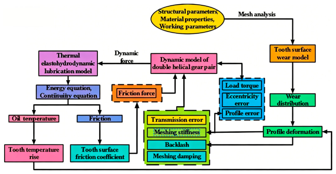
Figure 2 presents the calculation flowchart for dynamic excitation coupling. First, the structural material parameters, lubricating oil parameters, and operating conditions are determined. Subsequently, the meshing model, tooth wear model, and thermal elastohydrodynamic lubrication (TEHL) model of the double-helical gear pair are established, and the coupled excitation calculation is implemented. The tooth wear model provides the cumulative wear distribution along the tooth surface, which causes tooth profile deformation and consequently alters the internal excitation (meshing stiffness and backlash) and the external excitation (tooth profile error) of the dynamic model. The double-helical gear dynamic model supplies dynamic loads to the TEHL model; in turn, the friction force and friction torque provided by the lubrication model serve as inputs to the dynamic model.
The uncertainty in the manufacturing and installation process leads to the tooth profile being prone to deviation and eccentricity errors, which can be expressed as [18]:
e m ( t ) = e r sin ( 2 π f c t + θ 1 ) + e f ( t ) + e 0 ( t )
where er is the eccentricity error; θ 1 is the eccentricity error phase angle; e0 is the random component of the meshing error; and e f ( t ) is the meshing error caused by the tooth profile deviation.
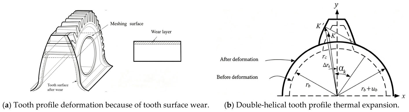
The adhesive wear is calculated using the model shown in Figure 3a [19], while the calculation method of single-point cumulative wear on the contact surface is:
h i , j = h i 1 , j + 4 a p k ι | v p v q v j |
where index j is equal to p or q; k ι is the wear rate; h is the wear depth; a is the contact half-width; p is the contact pressure; and vp and vg are the rolling speeds of the gear and pinion, respectively.
As shown in Figure 3b, the temperature rise on the tooth surface causes the gear to expand, while the shape of the tooth profile is also forced to change, causing it to deviate. The degree of deviation is expressed by involute error. In the case, where the tooth profile error is alone considered, is expressed in [20] as:
ζ T i ( t ) = Δ f ( t ) λ r b i ( r b i + u b i ) 2 × r b i + u b i cos α k i + Δ f ( t ) λ r b i ( 1 cos α k i × s i r b i 2 ( i n v α k i i n v α )
α k i = arccos ( r b i + u b i ) r c i ( t )
where Δ f is the instantaneous contact temperature rise in the gear; s is the tooth thickness on the reference circle; r b i (i = 1, 2) represents the base radius of the gear and pinion, respectively; r c i (i = 1, 2) represents the distance from the center of the gear or pinion to the meshing point, respectively; λ is the linear expansion coefficient of the gear material; α k i is the pressure angle of any point on the gear tooth profile, after thermal deformation; and (i = 1, 2) respectively represent the change in thermal deformation of the gear and pinion, on the base circle, when u b i , the gear transmission, is in stable operation. The negative sign indicates that the theoretical involute tooth profile is within the actual gear tooth profile.
u b i = λ r b i T r o i + 1 + κ 1 κ × λ r b i [ r b i 2 ( 1 2 κ ) r o i 2 ] r b i 2 r o i 2 × ( T r b i T r o i )
where T r o i represent the temperature of the gear and pinion transmission shaft during stable operation; T r b i represent the temperature of the gear and pinion on the base circle, during stable operation; r o i represent the radius of the gear and pinion at the shaft hole; and κ is the temperature rise coefficient of the helical gear.
Therefore, the tooth profile deviation due to wear and temperature rise is:
( ζ T + Δ T , h K ) p , g = i = 1 K h i k p , g + ζ T + Δ T p , g
where i = 1 K h i k p , g represents the cumulative wear amount of the gear p or the pinion g during the kth meshing. ζ T + Δ T p , g represents the tooth profile deviation of the gear and the pinion due to the temperature rise.
Converting the tooth profile error of the gear into a comprehensive equivalent error along the meshing line is as follows:
e f = ( ζ T + Δ T , h K ) s / cos β + ( ζ T + Δ T , h K ) p / cos β
e f ( t ) = i = 1 M e f sin ( 2 π i f m t + φ 2 )
where e f and θ 2 are the amplitude and initial phase angle of the meshing error, respectively, caused by the deviation of the tooth profile; and f m is the meshing frequency of the gear, with M being the harmonic order, generally ranging from 3 to 5.
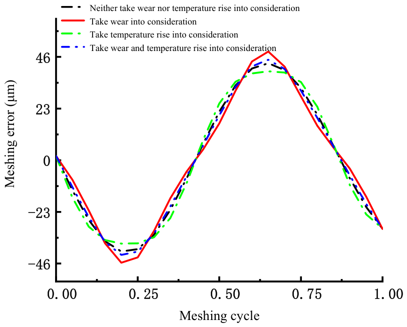
In order to compare whether temperature rise is taken into consideration or not, as well as the influence of tooth surface wear on the meshing error, the tooth surface temperature rise is set to 30 °C and the gear system operation times to 106. The meshing errors of the meshing pair under different considerations are obtained, and the fitting curves are shown in Figure 4. It can be seen that the shape of the meshing error curves under different considerations is the same. Under the four different considerations, the largest meshing error amplitude value is obtained when taking wear into meshing error consideration, and the smallest meshing error amplitude value is obtained when taking temperature rise into meshing error consideration. Compared with the case where neither wear nor temperature rise is considered, the meshing error amplitude value is smaller in both cases where wear or temperature rise is considered.
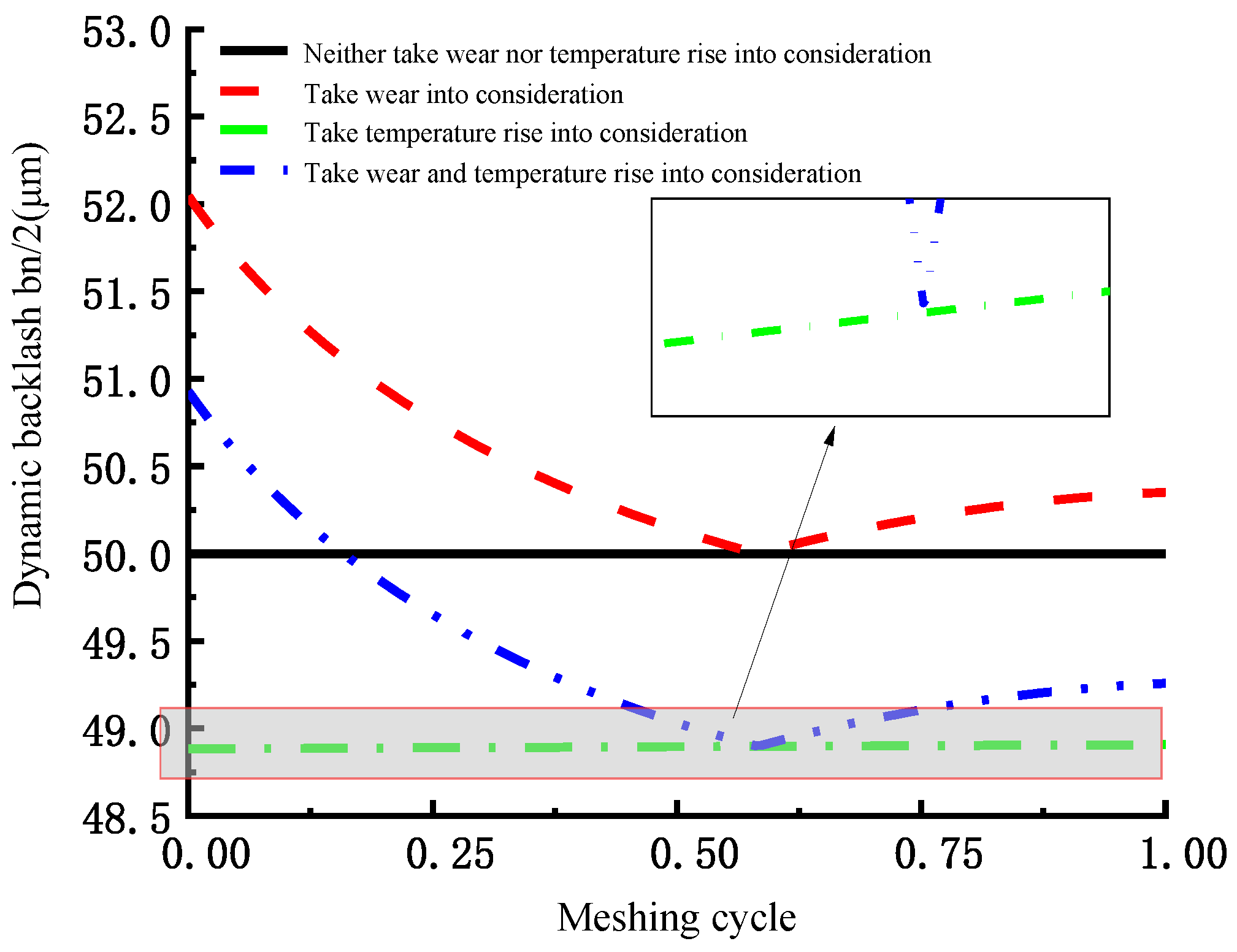
Figure 5 shows the curve of dynamic gear backlash in a meshing cycle under different considerations. The initial half of the gear backlash is set to 50 μm; that is, the gear backlash is kept constant without considering tooth surface wear and temperature rise. When taking tooth surface wear into consideration, the gear backlash value is larger than 50 μm. In addition, the gear backlash value is smaller than 50 μm when considering the temperature rise. However, the gear backlash value is first larger than 50 μm and then smaller than 50 μm in a meshing period when both wear and temperature rise are considered. In a meshing period, the dynamic backlash value decreases at first and then increases when either taking wear into consideration or taking wear and temperature into consideration, but the dynamic backlash value increases slowly when taking temperature into consideration.
In order to calculate the meshing stiffness of double-helical gears, considering the temperature rise and the wear of the tooth surface, the deformation of gear teeth along the meshing line, at the point of load, is first calculated, based on the Weber energy method [18].
δ Ξ j = δ z , j + δ R , j + δ p e , j + h i , j + ζ T , j
The time-varying meshing stiffness of the gear teeth is then described as:
k m ( t ) = 1 j = L , R k = 1 n j ( t ) 1 k j k ( t ) , k j k ( t ) = P δ b , j k ( t ) + δ r , j k ( t ) + δ c , j k ( t ) + w j k ( t ) + ζ T , j k ( t )
where δ z , j is the deformation caused by bending and shearing; δ R , j is the deformation of the tooth root part; δ p e , j is the deformation at the load application point, due to contact; while N is the number of gear meshing pairs.
Tooth wear and tooth profile deformation, caused by the temperature rise, affect the amount of backlash. After several wear cycles, assuming that the wear amount of a certain point on the gear is h1, the thermal expansion tooth deformation is GT1, the corresponding point wear amount of the pinion is h2, and the thermal expansion tooth deformation is GT2, the actual tooth backlash is:
b ( t ) = b 0 + δ e ( t ) + w 1 ( t ) + w 2 ( t ) ζ T 1 ( T s ) ζ T 2 ( T s )
The gap function [18] can be described as:
f gap ( Δ b , t ) = Δ b b ( t ) , Δ b > b ( t ) 0 , | Δ b | b ( t ) Δ b + b ( t ) , Δ b < b ( t )

2.2. Dynamic Model of Double-Helical Gear with Multiple Degrees of Freedom

The installation phase angle, as shown in Figure 1b, is expressed as:
ψ = φ α t
Considering the deformation of the tooth profile, caused by wear and temperature rise, the displacement of the tooth profile, and the eccentricity error, the relative displacement of the meshing pair along the meshing direction δm(t) can be expressed as:
δ m i ( t ) = [ ( y pi y g i ) cos ψ + ( x p i x g i ) sin ψ + R p i θ p i + R g i θ g i ] cos β + ( R p i θ p x i + R g i θ g x i ) sin ψ + ( R p i θ p y i + R g i θ g y i ) cos ψ + z p i z g i sin β + e r ( sin θ g i sin θ p i ) cos ψ cos β + e r ( cos θ g i cos θ p i ) sin ψ cos β e f f a , f p t ( t ) ζ T i ( t ) ζ h i ( t )
where er is the eccentricity error; ζ T i is the error of the tooth profile deformation along the meshing line, as induced by the temperature rise in the tooth surface; while ζ h i is the error of the tooth profile deformation along the meshing line, caused by the wear of the tooth surface. The dynamic meshing force between meshing gear is:
F p i = k m i × f ( δ m i ( t ) ) + c m i × δ · m i ( t )
The force of tooth surface friction is:
τ fric = sgn ( v s ( t ) ) × u F p i
where cm is the damping of the meshing pair; km is the mesh stiffness; Fpi is the meshing force; vs is the relative sliding speed of the meshing point; and sgn(x) is the sign function, while its expression is:
sgn ( v s ) = 1             v s 0 0             v s = 0 1         v s 0
The component forces Fx, Fy, Fz along the x, y, and z directions are:
F x = F p i sin ψ cos β + F f i cos ψ cos β F y = F p i cos ψ cos β + F f i sin ψ cos β F z = F p i cos ψ sin β
The dynamics expression of the gear system is:
m p x ¨ p + c p z ( t , T s ) x ˙ p + k p z ( t , w ) f gap ( x p , t ) = F x ( t ) + F unb , x ( t ) m p y ¨ p + c p z ( t , T s ) y ˙ p + k p z ( t , w ) f gap ( y p , t ) = F y ( t ) + F unb , y ( t ) m p z ¨ p + c p z ( t , T s ) z ˙ p + k p z ( t , w ) f gap ( z p , t ) = F z ( t ) ζ T ( t ) I p L θ ¨ p L = k m L ( t ) R p L sin β sin ψ F p L ( t ) sgn ( θ ˙ p L ) μ L ( t ) R p L F p L ( t ) + T p L 2 I p R θ ¨ p R = k m R ( t ) R p R sin β cos ψ F p R ( t ) sgn ( θ ˙ p R ) μ R ( t ) R p R F p R ( t ) + T p R 2 I p L θ ¨ p L = F p L ( t ) R p L cos β F p L ( t ) R p L cos β + T p L 2 + τ fric , L ( t ) m p x ¨ p + c p z ( t , T s ) x ˙ p + k p z ( t , w ) f gap ( x p , t ) = F x ( t ) F unb , x ( t ) m p y ¨ p + c p z ( t , T s ) y ˙ p + k p z ( t , w ) f gap ( y p , t ) = F y ( t ) F unb , y ( t ) m p z ¨ p + c p z ( t , T s ) z ˙ p + k p z ( t , w ) f gap ( z p , t ) = F z ( t ) + ζ T ( t ) I p R θ ¨ p R = k m R ( t ) R p R sin β cos ψ F p R ( t ) + sgn ( θ ˙ p R ) μ R ( t ) R p R F p R ( t ) T p R 2 I p L θ ¨ p L = k m L ( t ) R p L sin β sin ψ F p L ( t ) + sgn ( θ ˙ p L ) μ L ( t ) R p L F p L ( t ) T p L 2 I p θ ¨ p = F p R p cos β F p R p cos β + T p 2
where i is L or R, representing the left meshing pair and the right meshing pair, respectively; m and I are the gear mass and inertia, respectively; c is the supporting damping of bearing; k is the supporting stiffness of bearing; β is the helix angle, which takes a positive value when the drive wheel is in right rotation and a negative value otherwise; and F unb represents the radial unbalanced excitation force induced by the mass eccentricity of rotating components.
Based on the Timoshenko beam theory and finite element method, the differential equation of double-helical gear pair motion, written in matrix form, can be obtained as:
M ( t ) X .. + C ( t , X . , T s ( t ) ) X . + K ( t , w ( t ) , T s ( t ) ) f gap ( X , t ) = P ( t ) + F p ( t )
where M is the system mass matrix; C is the system damping matrix; K is the system time-varying meshing stiffness matrix; X is the system generalized coordinates column vector; and P is the static load of the system.

3. Thermal Hybrid Elastohydrodynamic Model

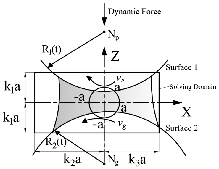
Figure 6 shows the lubrication model of the herringbone gear pair. The meshing contact of herringbone gears is equivalent to point contact; a is the Hertz contact radius, and R1(t) and R2(t) are the equivalent radii of curvature of the pinion and gear. Table 1 lists the transmission parameters of the double-helical gear pair. Table 2 lists lubricating oil parameters and material properties of gears, as used for calculation.

3.1. Theoretical Basis of Lubrication Model

3.1.1. Reynolds Equation

The simplified form of the Reynolds equation for elastohydrodynamic lubrication is [21,22,23]:
x ( ρ h 3 η p x ) + y ( ρ h 3 η p y ) = 12 v c ( ρ h ) x
where vc is the entrainment velocity; p is the pressure of the oil film; h is the thickness of the oil film; ρ is the density of the lubricating oil; and η is the viscosity of the lubricating oil.
Considering the meshing process of a pair of involute helical gears, Rp and Rg are the pitch circle radii of the two gears, ωp and ωg are the rotational angular speeds of the gears, φ is the pressure angle of the end faces of the indexing circle, while s is the distance from the meshing point to the pitch point P.
Considering point K is the intersection of the contact line and the front-end surface of the tooth surface, while the curvature radii at point K are R1 and R2, respectively.
R 1 = ( R p sin φ + s ) / cos β R 2 = ( R g sin φ s ) / cos β
According to the geometric characteristics of the helical gear, at point K, the normal radius of curvature of the two tooth surfaces is:
R s = R 1 R 2 R 1 + R 2
The relative entrainment velocity of the oil film between the two tooth surfaces at the meshing point K is:
  v p = ω p R 1 v g = ω g R 2   v c = v p + v g / 2

3.1.2. Film Thickness Equation Considering Tooth Surface Roughness

According to reference [24], the oil film thickness is composed of a rigid central film thickness, a geometric film thickness, an elastic deformation and a comprehensive tooth surface roughness. Assuming the surface of the gear teeth of the gear p is completely smooth, the surface of the gear p is rough, and there is a single rough peak at x = x0 in the contact area of the pinion g, the function of this single rough peak is expressed as:
R r ( x , y ) = 0.5 A b 1 + cos π l b ( x x 0 )
l b x x 0 l b
where Ab is the peak roughness and lb is the wavelength of the rough wave.
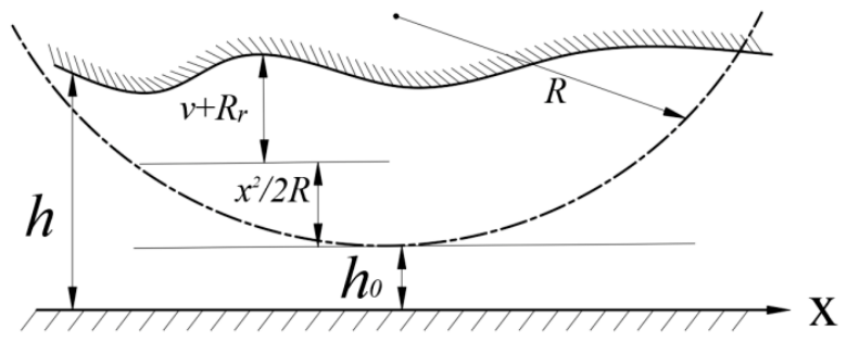
As shown in Figure 7, the mathematical expression of oil film thickness is:
h = h 0 + x 2 2 R + ν ( x , y ) + R r ( x , y ) + h 1 + h 2
Assuming a pressure distribution on the elastic surface, the deformation displacement ν(x,y) at each point on the surface is given by:
ν ( x , y ) = 2 π E Ω p ( x , y ) x 2 + y 2 d x d y
where h0 is the center oil film thickness; R is the comprehensive radius of curvature of the tooth profile of the two teeth at the meshing point; E is the comprehensive elastic modulus of the two gears; and R r ( x , y ) are the tooth surface roughness values.

3.1.3. Lubricating Oil Viscosity-Pressure and Viscosity-Temperature Equation

η = η 0 exp ( ( ln η 0 + 9.67 ) ( 1 + ( 1 + 5.1 × 10 9 p ) z 0 ( T 138 T 138 ) s 0 ) )
where η 0 is the lubricating oil viscosity; T0 is the ambient temperature; while z0 and s0 are the viscosity-pressure and viscosity-temperature parameters, respectively. The relationships between z0, s0, the Barus viscosity-pressure coefficient ξ , and the viscosity-temperature coefficient ξ are as follows:
z 0 = ξ / ( 5.1 × 10 9 ( ln η 0 + 9.67 ) )
s 0 = ς ( T 0 138 ) / ( ln η 0 + 9.67 )

3.1.4. Dense Temperature and Pressure Equation

With regard to the oil film temperature, according to Dowson and Higginso’ s density-pressure rule, fluid density is related to the pressure [25], as:
ρ = ρ 0 ( 1 + 0.6 × 10 9 p 1 + 1.7 × 10 9 p ) ( 1 ε ( T T 0 ) )
where ρ 0 is the density of lubricating oil and ε is the coefficient of thermal expansion.

3.1.5. Load Equation and Energy Equation

p ( x , y ) d x d y = W
c p ρ p v p T x = k p 2 T z p 2 c g ρ g v g T x = k g 2 T z g 2
where W is the amount of load supported by the lubricating film. cp, cg, ρ p , ρ g and kp, kg are the specific heat, density and thermal conductivity of gear p and gear g, respectively. zp and zg are gear p and g coordinates along the z direction of the oil film, respectively.

3.1.6. Coefficient of Friction

The shear stress equation is as follows.
On the lubricated surface with y = 0, the shear force is:
τ = h 2 p x + η h v g v p
On the lubricated surface of y = h, the shear force is:
τ = h 2 p x + η h v g v p
The total friction along the motion direction is:
F f = τ | y = 0 , h d x d y
μ = F f W

3.2. Lubrication Model Solution Area and Boundary Conditions

The solution domain is defined as a rectangular region extending from −4a to 2a in the x direction and from −2a to 2a in the y direction, where a is the Hertzian contact half-width [22]. This domain is centered around the nominal contact zone and is sufficiently large to capture the full pressure and film thickness distributions in both the inlet and outlet regions of the point-contact EHL problem.
x , y x i n < x < x o u t , y i n < y < y o u t
where a is the half-width of the Hertz contact area of the middle section.
Boundary conditions are as follows:
P ( x i n , y ) = 0 ,   P ( x o u t , y ) = 0 , P ( x o u t , y ) x = 0 ,   P ( x , y ) 0

3.3. Calculation Flowchart

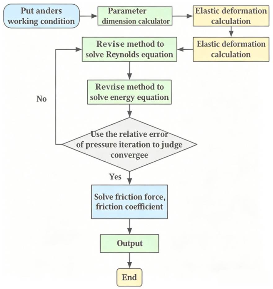
Figure 8 depicts the calculation flowchart for point-contact thermal elastohydrodynamic lubrication. In the numerical iterative calculation, five grid layers are used; the calculation domain is divided into a different number of nodes on each layer, and the central film thickness variable H0 is adjusted according to the lowest grid layer. The Reynolds equation is solved iteratively using the Gauss–Seidel relaxation method. At each cycle, a convergence criterion is applied to determine whether to proceed to the next cycle. The convergence judgment for the iteration is as follows [24].

3.4. Lubrication-Dynamic Coupling Model for Double-Helical Gear

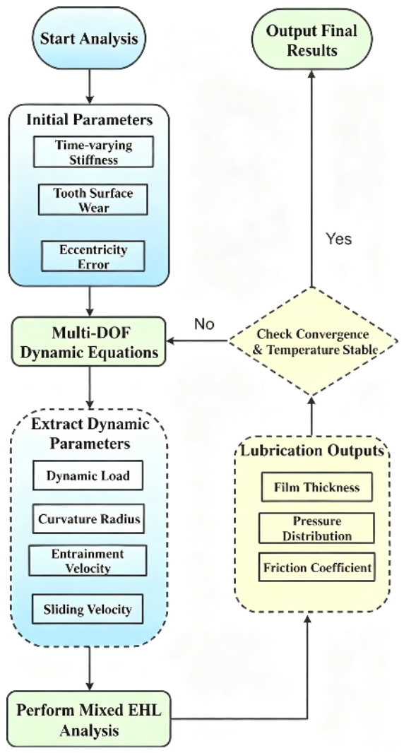
When analyzing the gear transmission system, it is necessary to consider both the influence of tribological characteristics on its dynamic behavior and the effect of dynamic meshing force on the lubricating oil film covering the tooth surface, as well as the resulting temperature rise. A multi-degree-of-freedom dynamic model for the double-helical gear pair is established based on dynamic and thermal elastohydrodynamic lubrication, taking into account the time-varying meshing stiffness of the gear teeth, tooth surface wear, and eccentricity error.
The Reynolds equation is discretized by finite differences on a 257 × 257 grid and solved using Gauss–Seidel with successive over-relaxation. The convergence criteria are 1 × 10⁻⁵ for the TEHL pressure and 1 × 10⁻⁶ for the dynamic solver. Time integration uses a 4th-order Runge–Kutta scheme with a fixed step of 1 × 10⁻⁵ s. Zero initial conditions are assumed, with the first 50 cycles excluded. Rayleigh damping is adopted, with coefficients from finite element modal analysis.
As shown in Figure 9, the calculation process is as follows. First, the dynamic equation is solved to obtain dynamic parameters at different meshing instants, including dynamic tooth load, radius of curvature, entrainment velocity, and relative sliding velocity. Subsequently, the TEHL analysis is performed to update the friction coefficient. The dynamic equation is then updated with the new friction coefficient, and the dynamic load is compared with the previous iteration. For the algebraic system, the Gauss–Seidel method with successive over-relaxation (SOR) is used with a relaxation factor of 1.2 and a maximum of 1000 iterations. The dynamic equations are integrated using a 4th-order Runge–Kutta scheme with a fixed time step of 1 × 10⁻⁵ s (~2000 steps per mesh cycle). Rayleigh damping with a modal ratio of 0.03 is adopted. Each case requires approximately 120 min of CPU time on a standard workstation (Intel Core i7, 3.2 GHz, 32 GB RAM).

4. Result Analysis and Discussion

4.1. Vibration Analysis and Discussion of the Double-Helical Gear Pair

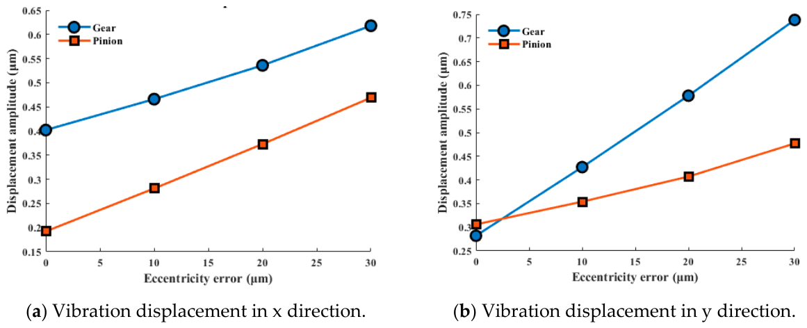
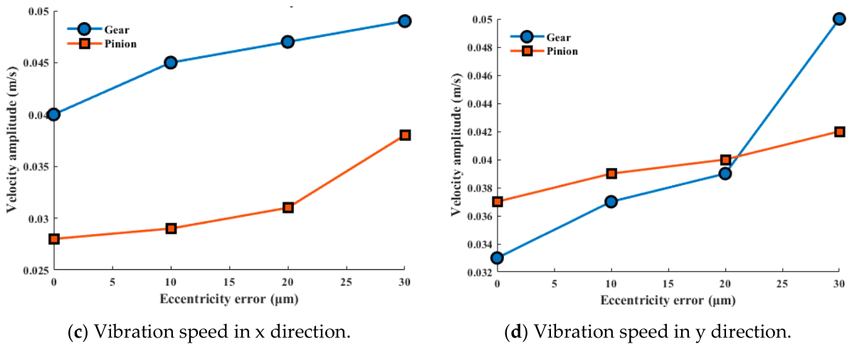
Unlike conventional approaches that treat dynamics and lubrication separately, the present model incorporates a bidirectional feedback loop between these two domains. Figure 10 presents the vibration displacement (x and y directions) and vibration velocity (x and y directions) of the double-helical gear and the pinion under different eccentricity errors. With increasing eccentricity error, both the displacement and velocity amplitudes of the gear and pinion increase monotonically in both directions.
Taking the gear as an example (see Table 3), compared with the case of 30 μm eccentricity error, the vibration displacement in the x direction decreases by 13.3%, 24.6%, and 34.9% when the eccentricity error is reduced to 20 μm, 10 μm, and 0, respectively. In the y direction, the displacement decreases by 21.7%, 42.1%, and 61.8%, respectively. For the vibration velocity in the x direction, the reductions are 4.1%, 8.2%, and 18.4% (corrected from the originally reported 16.1% based on the actual data), respectively. In the y direction, the velocity reductions are 22%, 26%, and 34%, respectively.
A comparative analysis of the relative changes reveals a clear differential sensitivity: increasing the eccentricity error from 0 to 30 μm leads to a 61.8% increase in the gear’s y-direction displacement, but only a 34% increase in its y-direction velocity. The ratio of displacement change to velocity change is approximately 2:1, indicating that vibration displacement is more sensitive to assembly errors than vibration velocity. This suggests that displacement-based diagnostics may be more effective for detecting eccentricity faults in double-helical gear transmissions.
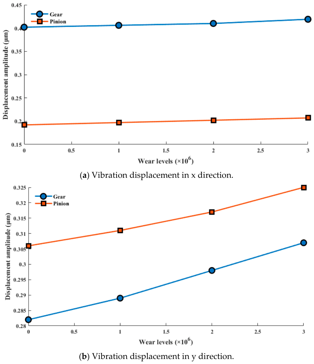
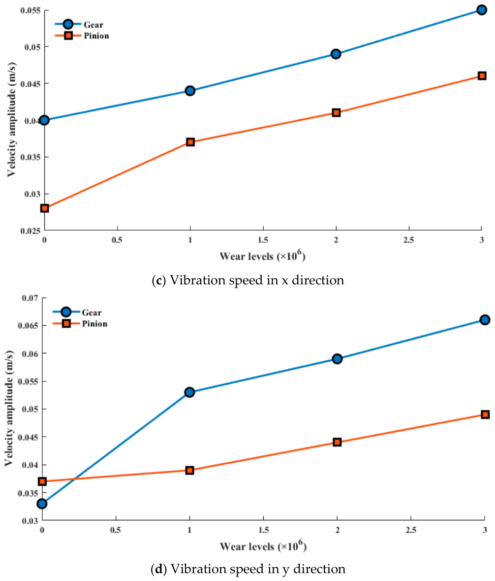
As shown in Figure 11, the vibration displacement and velocity of the gear and pinion in the x and y directions both increase with accumulated wear. Taking the gear as an example (see Table 4), compared with 3 × 10⁶ operation cycles, when the number of cycles is 2 × 10⁶, 1 × 10⁶, and 0, the vibration displacement amplitude in the x direction decreases by 2.1%, 3.1%, and 4.1%, respectively, and the vibration displacement amplitude in the y direction decreases by 2.9%, 5.8%, and 8.1%, respectively. Moreover, the vibration velocity amplitude in the x direction decreases by 10.9%, 20.0%, and 27.2%, respectively, and the vibration velocity amplitude in the y direction decreases by 10.6%, 19.7%, and 50.0%, respectively.
It can be concluded that accumulated wear has a greater influence on vibration velocity than on vibration displacement. In contrast to the eccentricity case, where displacement was more sensitive, wear affects vibration velocity much more strongly. After 3 × 10⁶ cycles, the vibration velocity of the gear in the y direction increases by 50% compared with the unworn state, while the displacement increases by only 8.1%. This indicates that vibration velocity is a more sensitive indicator for wear monitoring. Therefore, condition monitoring systems for double-helical gears should prioritize velocity measurements when wear is the primary concern, and displacement measurements when assembly errors dominate.
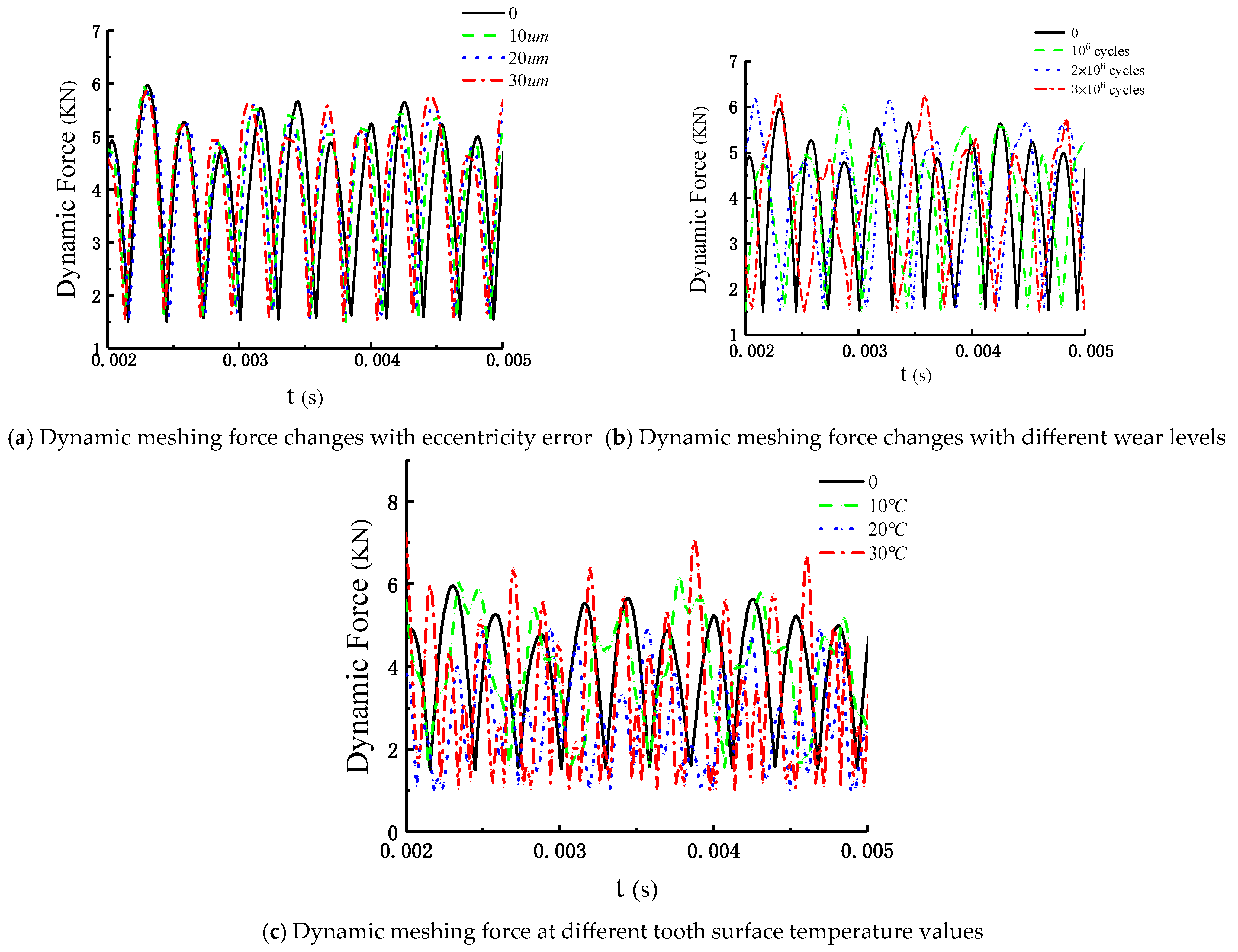
Figure 12 illustrates the dynamic meshing force of a double-helical gear under different operating conditions. As the eccentricity error increases, both the amplitude and the fluctuation of the dynamic meshing force increase, which in turn raises the vibration amplitude of the double-helical gear system. During the wear process, the dynamic meshing force exhibits a continuous, repetitive, and nearly symmetric wave-like pattern. Its peak value initially rises rapidly with fluctuations, followed by a brief decline, and then increases sharply again. At this stage, a strong instantaneous impact force occurs on the meshing tooth surfaces, potentially leading to overload damage. The dynamic meshing force fluctuates periodically around its mean value. Under different tooth surface temperature rise conditions, the time-domain waveforms of the dynamic meshing force are generally similar in shape, but their peak values differ. Specifically, as the tooth surface temperature increases, the dynamic meshing force gradually rises. This increase amplifies the impact excitation, which subsequently causes the tooth surface friction coefficient and friction force to increase.
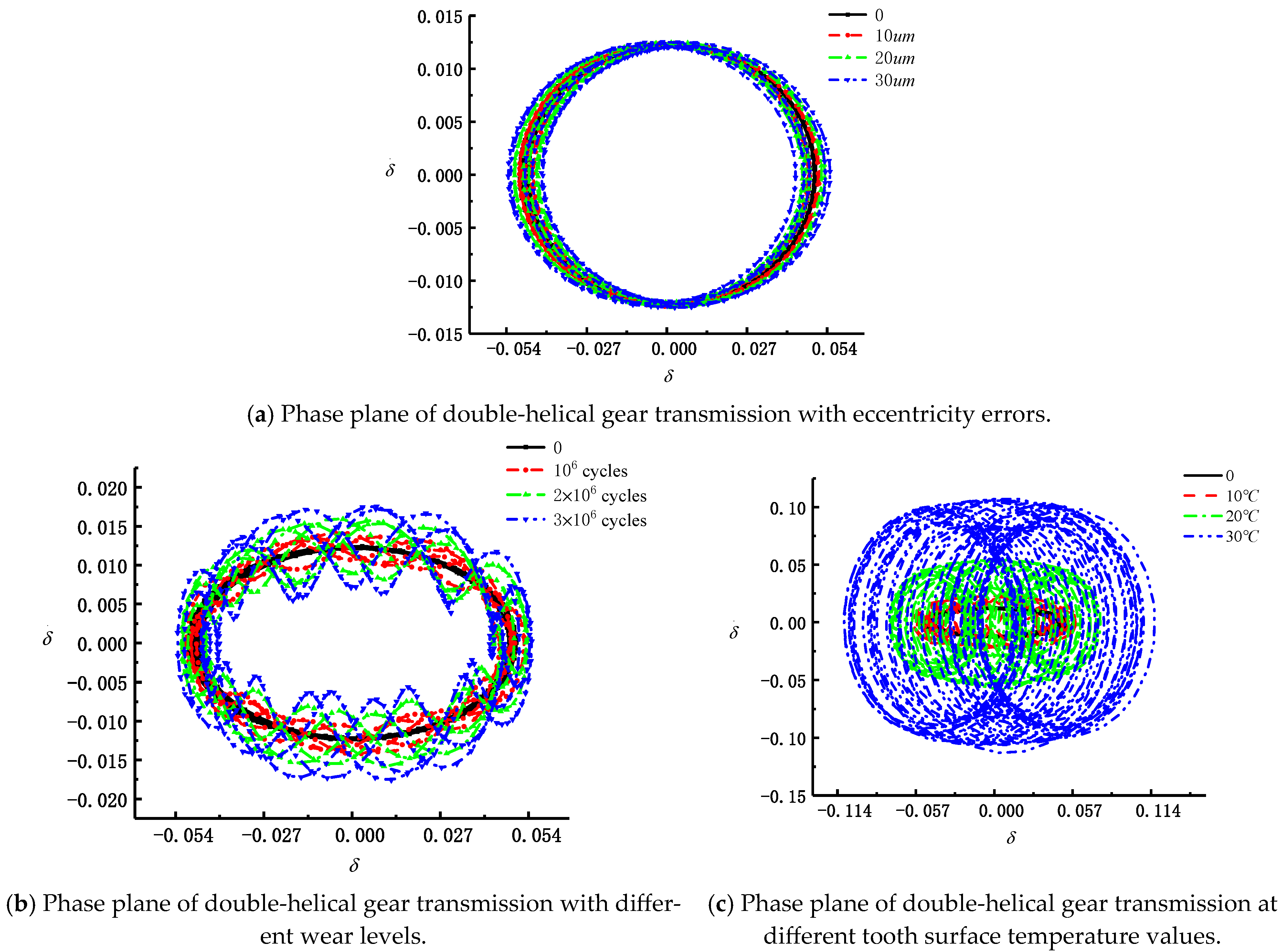
Figure 13 depicts the phase plane of the double-helical gear transmission under different operating conditions. As the eccentricity error increases, the trajectory on the phase plane expands. With higher wear levels, the trajectory not only expands but also exhibits more pronounced fluctuations. Under elevated tooth surface temperatures, more trajectories appear on the phase plane, and the range of motion becomes larger.

4.2. Wear and Lubrication Analysis of Double-Helical Gear Pair

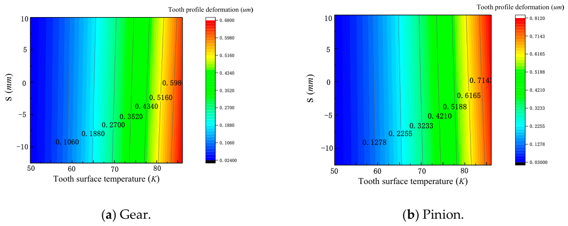
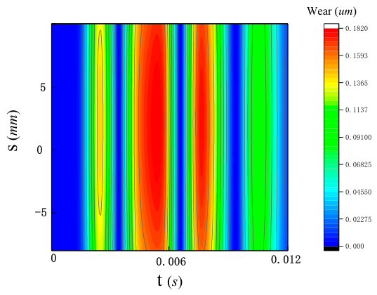
Figure 14 depicts the tooth profile deformation of the gear and pinion in relation to the tooth surface temperature rise. The tooth profile deformation increases as the tooth surface temperature rises. Under the same temperature rise, the tooth profile deformation of the gear is greater than that of the pinion. Figure 15 illustrates the variation in wear at different positions on the tooth surface after 106 operation cycles of the meshing pair. The distribution of tooth surface wear along the meshing line shows that wear is minimal at the pitch node and intensifies with increasing distance from the node. Consequently, wear is highest at the tooth root, followed by the tooth tip, and lowest at the pitch node.
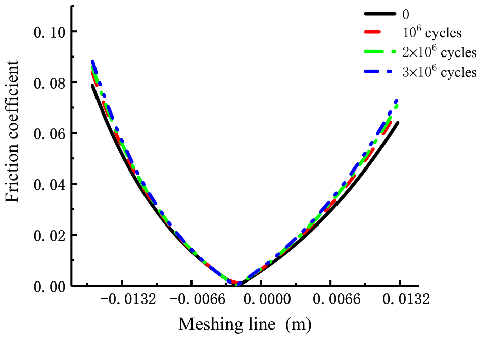
Figure 16 shows the friction coefficient distribution along the meshing line under different wear levels. The curves exhibit a symmetric U-shape, with the minimum at the pitch point (zero sliding velocity) and maxima at the ends. As wear accumulates (0 to 3 × 10⁶ cycles), the entire curve shifts upward, especially at the addendum and dedendum where sliding speeds are highest. The friction coefficient at the pitch point remains near zero for all wear states, indicating pure rolling. However, increased wear degrades the lubrication state, reducing film thickness and promoting boundary/mixed lubrication. This leads to higher shear stress and elevated friction coefficients. Progressive wear thus not only alters tooth geometry but also impairs tribological performance, affecting dynamic load sharing, vibration excitation, and energy efficiency.

4.3. Benchmarking of the TEHL Solver

The TEHL solver was benchmarked against the Hamrock-Dowson formula for a representative case (500 N, 10 m/s, 80 °C). The predicted central film thickness (0.82 μm) and friction coefficient (0.042) agree with the analytical solutions within 7% relative error, confirming the numerical reliability of the lubrication solver.

5. Experimental Research

5.1. Test Equipment

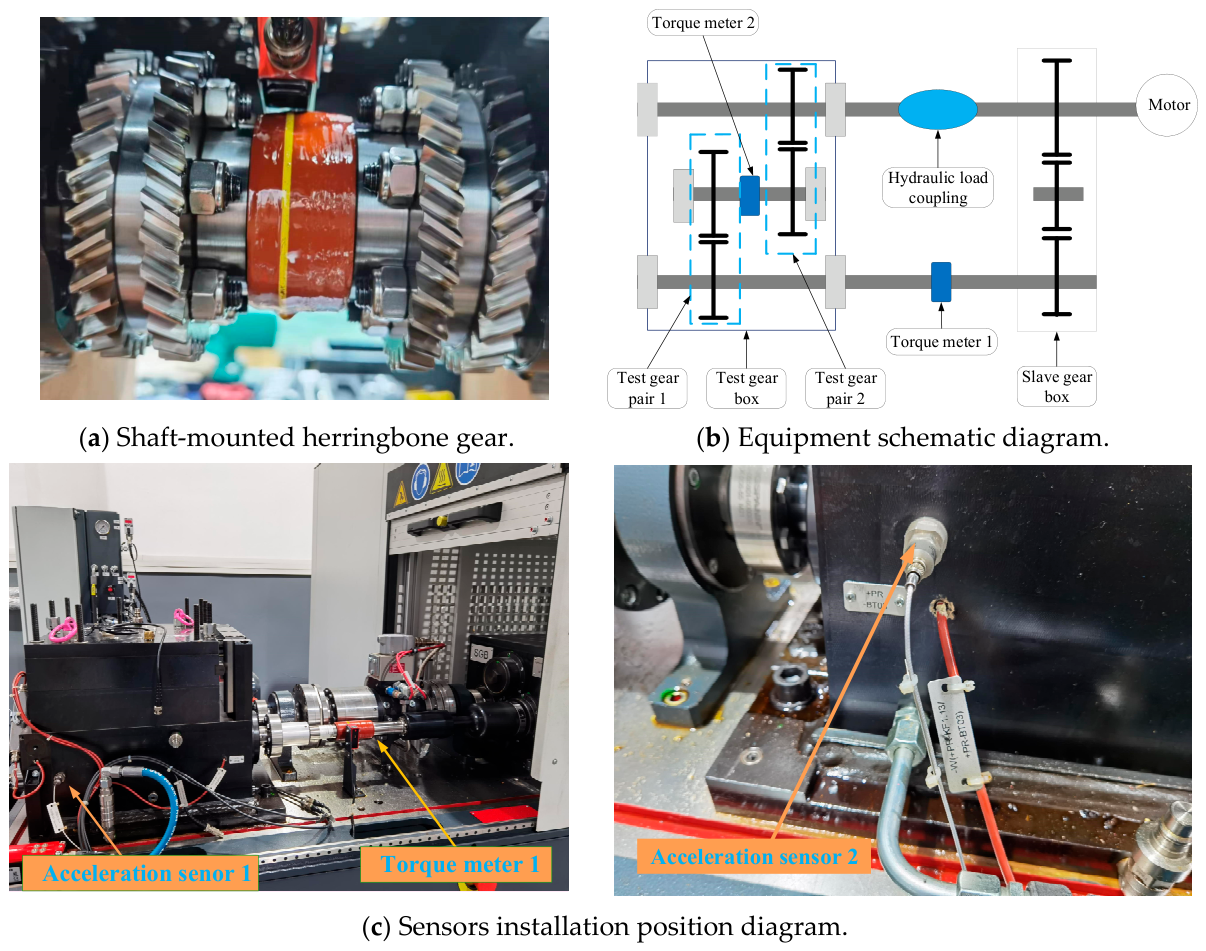
The vibration characteristics of the double-helical gear were tested on an FZG gear test rig (Strama-MPS Maschinenbau GmbH & Co. KG, Ittlinger Str. 195, 94315 Straubing, Germany) operating on the power-loop principle, consisting of a slave gearbox and a test gearbox connected by two shafts with a hydraulic load clutch for torque application, where a non-contact torque sensor measures torque in real time and an acceleration sensor collects vibration signals for analysis. The accelerometer was mounted on the bearing housing in the radial direction with its sensitive axis aligned with the line of action; the sampling rate was 25.6 kHz per channel with a 4th-order Butterworth low-pass filter at 5 kHz cutoff. FFT analysis used a Hanning window with 50% overlap and 0.5 Hz resolution, and all reported acceleration amplitudes are peak values (zero-to-peak). Figure 17 shows the test rig and the sensor layout.
The test equipment can measure torque, vibration acceleration, and oil temperature throughout the gearbox. The torque was measured using a non-contact torque sensor (HBM, Darmstadt, Germany), the rotational speed was recorded by an encoder (Heidenhain, Traunreut, Germany), and vibration acceleration was acquired using a piezoelectric accelerometer (Kistler Typ 870350M5, Kistler Group, Winterthur, Switzerland). The oil temperature was monitored using a PT100 sensor (accuracy ±1 K).The measurement accuracy of the sensor is shown in Table 5.

5.2. Comparative Analysis of Test Results

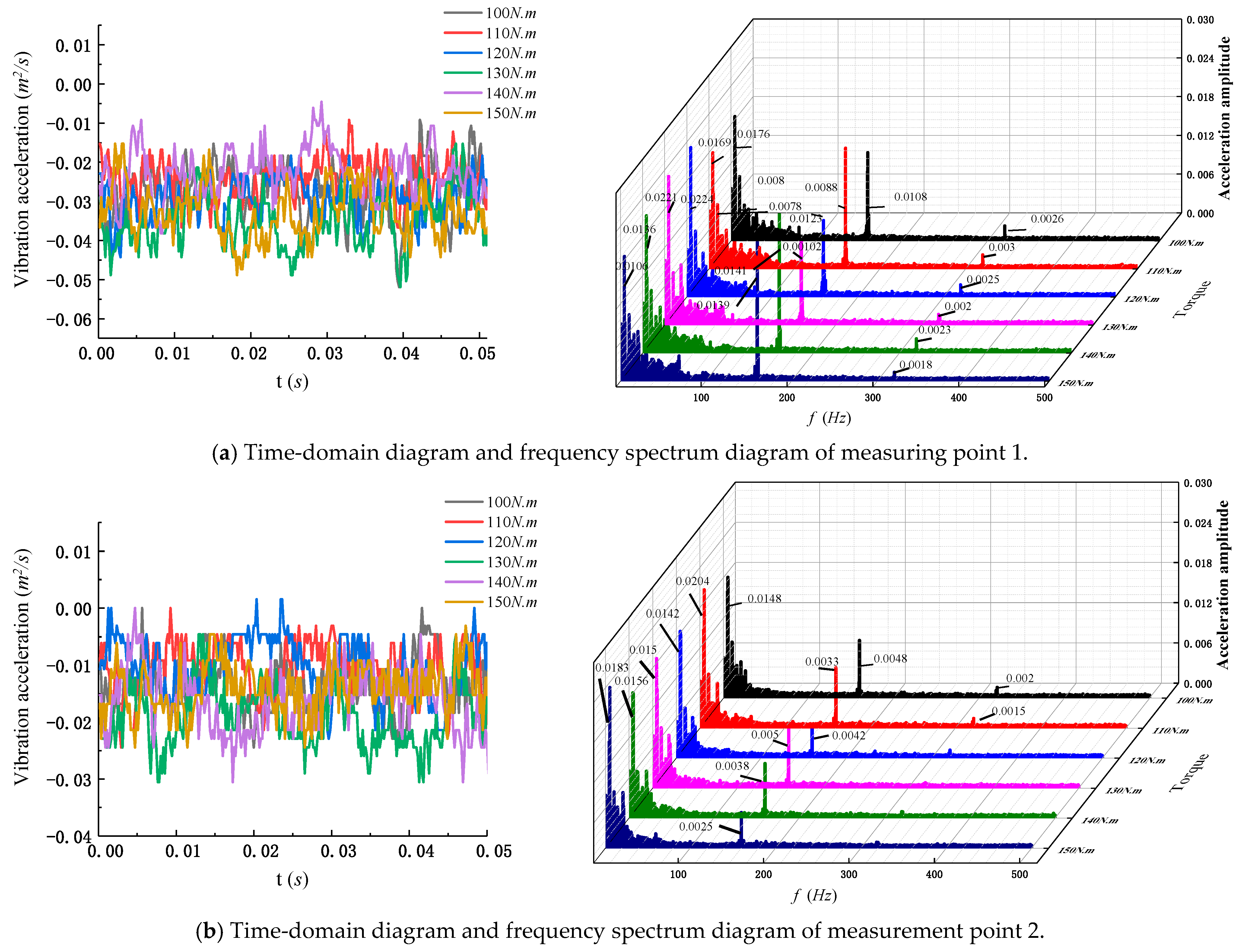
Acceleration sensors were fixed on the gearbox to measure the vibration of the double-helical gear pair. A total of 15 operating conditions were tested, covering input speeds from 100 to 500 rpm and torques from 100 to 200 N·m. Among these, Table 6 summarizes the results under light-wear conditions (100, 200, and 300 rpm at 100 N·m), while Table 7 presents the theoretical and experimental vibration acceleration values for all 15 operating conditions, along with the corresponding errors. Figure 18 shows representative time and frequency domain diagrams for two measurement points under a subset of conditions (100 rpm, torque varying from 100 to 150 N·m). Based on these measurements, the vibration characteristics of the double-helical gear transmission system under different working conditions were obtained.
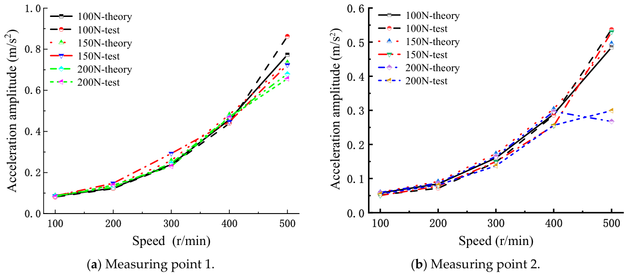
Figure 18 shows the vibration acceleration time-domain diagrams and frequency spectra for the two measurement points when the input speed is 100 rpm and the torque varies from 100 N·m to 150 N·m. It can be observed that the vibration acceleration amplitude does not increase monotonically with torque. As the load increases from 100 N·m to 120 N·m, the vibration acceleration rises; however, within the torque range of 120 N·m to 150 N·m, the vibration acceleration decreases. This indicates that multiple factors influence the vibration characteristics of the gear system, and the vibration acceleration does not change regularly with increasing load. Figure 19 compares the experimental and theoretical values. The trends of the experimental and theoretical values under different input speeds and operating conditions are consistent. The errors between all theoretical values and the corresponding experimental measurements are below 20%.
It should be emphasized that the experimental validation presented here is interpreted as a partial validation of the vibration response. The tribological aspects (TEHL, wear, and temperature sub-models) are supported by numerical benchmarking as presented in Section 4.3 rather than by direct experimental measurement. Direct validation of film thickness, contact temperature, and wear depth remains a direction for future work.

5.3. Summary

(1)
As the eccentricity error increases from 0 to 30 μm, the vibration displacement and velocity of the gear and pinion in both x and y directions increase monotonically. The gear’s y-direction displacement increases by 61.8%, while its y-direction velocity increases by only 34%, indicating that displacement is approximately twice as sensitive as velocity to assembly errors. Therefore, displacement-based diagnostics are more effective for detecting eccentricity faults.
(2)
With accumulated wear (up to 3 × 10⁶ cycles), the vibration displacement and velocity also increase. However, in contrast to eccentricity, wear affects velocity much more strongly than displacement: after 3 × 10⁶ cycles, the gear’s y-direction velocity increases by 50%, compared with only 8.1% for displacement. Hence, velocity is a more sensitive indicator for wear monitoring.
(3)
The dynamic meshing force increases in amplitude and fluctuation with eccentricity error, exhibits a nearly symmetric wave-like pattern during wear, and rises gradually with tooth surface temperature. The phase plane trajectory expands under all three excitations, with wear causing additional fluctuations and temperature enlarging the motion range.
(4)
Tooth surface wear is minimal at the pitch node and intensifies with distance from the node, being highest at the tooth root, followed by the tip, and lowest at the pitch node. Wear increases with operation cycles and input torque.
(5)
Under thermal elastohydrodynamic point contact, the film thickness, pressure, and temperature rise first increase and then decrease along the meshing line. The temperature rise in the contact zone increases rapidly and then declines. At the highest load position, film thickness is smallest while pressure and temperature rise are highest. The friction coefficient follows a U-shaped distribution along the meshing line and shifts upward with accumulated wear, indicating lubrication degradation.
(6)
Experiments on an FZG test rig (input speeds 100–500 rpm, torques 100–200 N·m) show that vibration acceleration does not increase monotonically with torque. The theoretical vibration accelerations agree well with experimental measurements, with errors below 20% for all operating conditions, validating the proposed tribo-dynamic coupled model.

6. Conclusions

A bidirectional tribo-dynamic coupled model for double-helical gear pairs has been developed. The main contributions of this work include the integration of tooth surface wear, thermal elastohydrodynamic lubrication, eccentricity error, and temperature rise into a unified framework, with a quantitative assessment of their differential effects on vibration displacement and velocity.
The primary mathematical contribution is the bidirectional coupling scheme between the dynamic model and the TEHL/wear sub-models, with explicit convergence criteria for iterative information exchange (Section 3.4). This coupling allows tribological evolution (wear accumulation and thermal expansion) to feed back into dynamic excitation by altering mesh stiffness and backlash. The integrated tooth profile deformation model (Equations (3)–(6)) reveals a non-monotonic backlash variation within a meshing cycle when both wear and thermal expansion are considered.
The quantitative analysis shows that eccentricity error, wear, and temperature rise affect vibration displacement and velocity with distinctly different sensitivities. Eccentricity error influences displacement more than velocity (ratio ≈ 2:1), while wear affects velocity more than displacement (after 3 × 10⁶ cycles, velocity increases by 50% vs. 8.1% for displacement). Temperature rise uniquely increases velocity while slightly decreasing displacement. These differential sensitivities offer potential diagnostic indicators for gear condition monitoring.
The TEHL sub-model predicts that the minimum film thickness and maximum pressure occur near the pitch point, with a temperature rise of approximately 35 K. The friction coefficient exhibits a U-shaped distribution along the meshing line and shifts upward with accumulated wear. The numerical solver has been benchmarked against classical solutions (Section 4.3), showing relative errors below 7%. Vibration acceleration measurements on an FZG test rig validate the vibration response part of the model, with errors within 20% for all tested conditions.
It should be noted that the experimental validation is limited to vibration acceleration; direct validation of film thickness, contact temperature, and wear depth remains for future work. The applicability to arbitrary gear pairs also requires further verification. Future research will focus on dedicated tribological experiments and extension to other gear types.

Author Contributions

Conceptualization, Y.W. (Yun Wang) and Y.W. (Yong Wang); methodology, Y.W. (Yun Wang); software, Y.W. (Yun Wang) and W.W.; validation, Y.Z.; formal analysis, Y.W. (Yun Wang) and H.X.; investigation, Y.W. (Yun Wang); resources, Y.W. (Yong Wang) and H.X.; data curation, W.W. and Y.Z.; writing—original draft preparation, Y.W. (Yun Wang); writing—review and editing, Y.W. (Yun Wang); visualization, Y.W. (Yun Wang); supervision, Y.W. (Yong Wang), W.D., J.W. and W.Y.; project administration, Y.W. (Yun Wang); funding acquisition, Y.W. (Yong Wang), H.X., W.D. and W.Y. All authors have read and agreed to the published version of the manuscript.

Funding

This research was funded by the National Natural Science Foundation of China (Grant Nos. 52272361 and 52305052), the Science and Technology Research Program of Chongqing Municipal Education Commission (Grant Nos. KJQN202301516, KJQN202303101, KJZD-M202403101 and KJZD-M202503102), and the University-Level Projects of Chongqing Polytechnic University of Electronic Technology (Grant Nos. 25XJJSCX13 and 25XJJSCX03).

Data Availability Statement

The experimental data presented in this study are available upon reasonable request from the corresponding author. The data are not publicly archived due to internal laboratory policies.

Conflicts of Interest

Authors Yun Wang and Jiqing Wu were employed by the company Jiangsu Meike Solar Technology Inc. Jiangsu Meike Solar Technology Inc. was not involved in the study design; in the collection, analysis, or interpretation of data; in the writing of this article; or in the decision to submit this article for publication. The remaining authors declare that the research was conducted in the absence of any commercial or financial relationships that could be construed as a potential conflict of interest.

References

  1. Wang, Y.; Yang, W.; Tang, X. Research on the dynamic performance of double-helical planetary gear transmission under friction and wear. Proc. Inst. Mech. Eng. 2024, 238, 81–98. [Google Scholar] [CrossRef]
  2. Liu, L.; Wang, S.; Zou, H.; Chen, P. Design and experimental study on vibration reduction of damping rings for four-branch star herringbone gear transmission. Results Eng. 2025, 27, 105937. [Google Scholar] [CrossRef]
  3. Guo, W.; Bao, H.; Cao, J.; Zhou, Y. Accuracy analysis of herringbone gear transmission based on measured symmetry error. Ind. Lubr. Tribol. 2025, 77, 349–360. [Google Scholar] [CrossRef]
  4. Liu, X.; Fang, Z.; Lei, F.; Kang, H.; Han, H.; Shen, Y.; Dong, H.; Fu, X. A novel method to study the long period three-dimensional vibration characteristics of herringbone gear with asymmetry pitch deviation. Mech. Syst. Signal Process. 2025, 224, 112040. [Google Scholar] [CrossRef]
  5. Shao, S.; Zhang, K.; Yao, Y.; Liu, Y.; Yang, J.; Xin, Z.; He, K. A study on the lubrication characteristics and parameter influence of a high-speed train herringbone gearbox. Lubricants 2024, 12, 270. [Google Scholar] [CrossRef]
  6. Yin, Z.; Liu, B.; Yang, C.; Wang, H.; Fu, X.; Fan, Z. Study on meshing power loss of helical gears with tooth surface wear under mixed elastohydrodynamic lubrication. Tribol. Int. 2026, 224, 112351. [Google Scholar] [CrossRef]
  7. Yu, X.; Shen, Z.; Sun, Y.; Wu, S. Parameterized prediction of gear surface wear incorporating mixed lubrication decoupling and deterministic wear modeling. Appl. Math. Model. 2026, 160, 117092. [Google Scholar] [CrossRef]
  8. Xiong, Q.; Liu, X.; Liu, Y.; Wang, J.; Zhang, J. Interaction between gear wear and dynamic behavior considering interface characteristics. Tribol. Int. 2025, 212, 111013. [Google Scholar] [CrossRef]
  9. Mo, S.; Zhang, Y.; Chen, K.; Zheng, Y.; Zhang, W. The influence of cumulative wear on the dynamic response and meshing state of gear system with mixed elastohydrodynamic lubrication. Nonlinear Dyn. 2025, 113, 21151–21179. [Google Scholar] [CrossRef]
  10. Wang, Y.; Yu, X.; Wu, C.; Luo, S.; Long, X. Initiation and evolution of interference wear and pitting for spur gears considering the concurrent effects of meshing impact and mixed lubrication. Tribol. Int. 2024, 200, 110081. [Google Scholar] [CrossRef]
  11. Liang, D.; Hu, H.; Wu, Y. Geometric design and dynamic characteristics analysis of a novel herringbone planetary gear. Proc. Inst. Mech. Eng. Part K J. Multi-Body Dyn. 2025, 239, 234–253. [Google Scholar] [CrossRef]
  12. Li, Z.; Zheng, J.; Li, B.; Liu, L.; Wang, S. Research and experimental verification on transmission performance of 3D modification herringbone gear. Nonlinear Dyn. 2025, 113, 20793–20823. [Google Scholar] [CrossRef]
  13. Zou, H.; Wang, S.; Chen, P.; Liu, L. Study on meshing and dynamic characteristics of herringbone gear pair considering tooth surface wear and modification. Proc. Inst. Mech. Eng. Part J J. Eng. Tribol. 2025, 239, 283–306. [Google Scholar] [CrossRef]
  14. Huang, W.; Hu, H.; Ma, H. Dynamic modeling and response analysis of cracked herringbone gear transmission systems with installation errors. Mech. Mach. Theory 2025, 206, 105924. [Google Scholar] [CrossRef]
  15. Yue, Z.; Wang, Z.; Chen, Z.; Qu, J.; Yu, G.; Wang, J.; Mo, S. Analysis of multi-state meshing and dynamic stability of herringbone gears considering friction based on nonlinear dynamics. Mech. Mach. Theory 2025, 206, 105909. [Google Scholar] [CrossRef]
  16. Mo, S.; Wang, D.; Chang, B.; Zhao, X.; Houjoh, H. Nonlinear dynamic characteristics analysis of herringbone gear transmission system with tooth root crack. Commun. Nonlinear Sci. Numer. Simul. 2025, 142, 108572. [Google Scholar] [CrossRef]
  17. Han, H.; Dong, H.; Zhang, D.; Bi, Y. Nonlinear dynamic modeling and dynamic characteristics analysis of a coaxial reverse closed differential herringbone gear transmission system considering floating backlash. J. Vib. Eng. Technol. 2025, 13, 69. [Google Scholar] [CrossRef]
  18. Li, R.; Wang, J. Dynamics Analysis of Gear System, 1st ed.; Science Press: Beijing, China, 2000. [Google Scholar]
  19. Janakiraman, V.; Li, S.; Kahraman, A. An investigation of the impacts of contact parameters on wear coefficient. J. Tribol. 2014, 136, 031602. [Google Scholar] [CrossRef]
  20. Gou, X.; Qi, C.; Chen, D. Nonlinear dynamic modeling and analysis of gear system considering tooth surface contact temperature. Chin. J. Mech. Eng. 2015, 11, 71–77. [Google Scholar] [CrossRef]
  21. Houpert, L.G.; Hamrock, B.J. Fast approach for calculating film thicknesses and pressures in elastohydrodynamically lubricated contacts at high loads. J. Tribol. 1986, 108, 411–420. [Google Scholar] [CrossRef]
  22. Kim, K.H.; Sadeghi, F. Three dimensional temperature distribution in EHD lubrication: Part II—Point contact and numerical formulation. Trans. ASME J. Tribol. 1993, 115, 36–45. [Google Scholar] [CrossRef]
  23. Dyson, A.; Wilson, A.R. Film thickness in elastohydrodynamic lubrication by silicone fluids. Proc. Inst. Mech. Eng. 1965, 180, 97–112. [Google Scholar] [CrossRef]
  24. Huang, P. Numerical Calculation Methods of Elastohydrodynamic Lubrication, 1st ed.; Science Press: Beijing, China, 2013. [Google Scholar]
  25. Dowson, D.; Higginson, G.R. A numerical solution to the elasto-hydrodynamic problem. J. Mech. Eng. Sci. 2006, 1, 6–15. [Google Scholar]
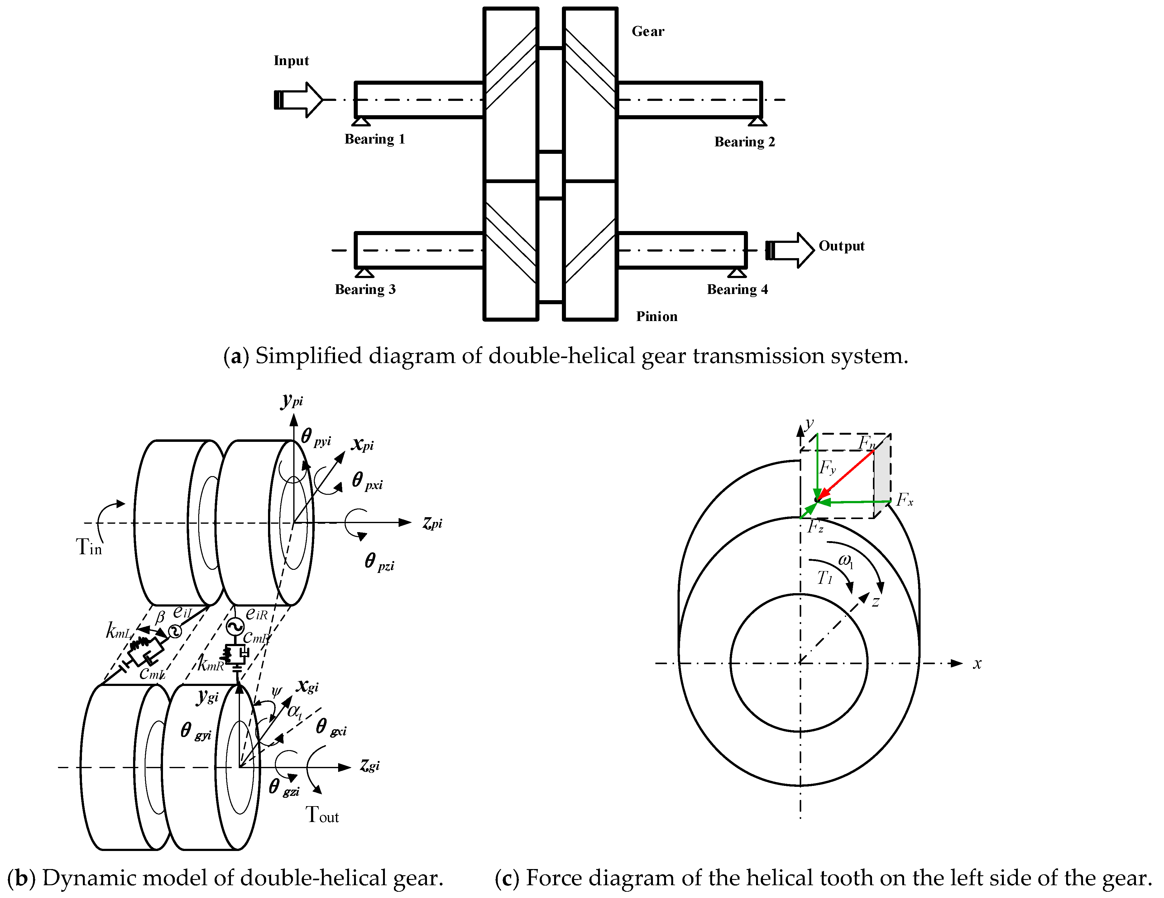
Figure 1. Schematic diagram of double-helical gear transmission system.
Computation 14 00166 g001
Figure 2. Calculation flow chart of dynamic excitation.
Computation 14 00166 g002
Figure 3. Deformation model of tooth profile.
Computation 14 00166 g003
Figure 4. Change curve of meshing error under different considerations.
Computation 14 00166 g004
Figure 5. Curve of dynamic gear backlash.
Computation 14 00166 g005
Figure 6. Lubrication model of double-helical gear pair.
Computation 14 00166 g006
Figure 7. Schematic diagram of oil film thickness.
Computation 14 00166 g007
Figure 8. Calculation flow chart for lubrication model.
Computation 14 00166 g008
Figure 9. Calculation flow chart for tribo-dynamic model.
Computation 14 00166 g009
Figure 10. Effect of eccentricity error on vibration behavior of the double-helical gear.
Computation 14 00166 g010aComputation 14 00166 g010b
Figure 11. Vibration displacement and vibration speed of gear at different wear levels.
Computation 14 00166 g011aComputation 14 00166 g011b
Figure 12. Dynamic meshing force at different working conditions.
Computation 14 00166 g012
Figure 13. Phase plane of double-helical gear transmission at different working conditions.
Computation 14 00166 g013
Figure 14. Gear tooth profile deformation along the meshing line, as the tooth surface temperature rises.
Computation 14 00166 g014
Figure 15. Variations in wear at different meshing positions with time.
Computation 14 00166 g015
Figure 16. Variation in friction coefficient along the meshing line with different operation numbers.
Computation 14 00166 g016
Figure 17. The double-helical test rig.
Computation 14 00166 g017
Figure 18. Vibration acceleration of measuring points in different working conditions.
Computation 14 00166 g018
Figure 19. Comparison of the results under different working conditions.
Computation 14 00166 g019
Table 1. Transmission parameters of double-helical gear pair.
Parameters/PerformanceGearPinion
Number of teeth3431
Mass m/(kg)1.621.28
Input speed/(rpm)500/
Torque/(N.m)/200
Inertia I/(kg·m−2)0.00410.0027
Support damping cx,y,z/(N.s/m)34003400
Support stiffness kx,y,z/(N/m)109109
Normal modulus mn/mm3
Normal pressure angle αn/deg20
Helix angle β/deg30
Tooth width B/mm35
Backlash b/mm0.05
Wear rate k ι 10−6
Table 2. Lubricating oil parameters and material properties of gear.
ParametersValue
Modulus of elasticity of gear and pinion E/(GPa)210
Poisson ratio of gear and pinion0.3
Density of gear and pinion ρ1,2/(kg·m−3)7850
Specific heat capacity of gear and pinion c1,2/(J·kg−1·K−1)470
Thermal conductivity of gear and pinion k1,2/(W·m−1·K−1)46
Linear expansion coefficient λ1.16 × 10⁻⁵
Viscosity of lubricating oil η0/(Pa·s)0.08
Density of lubricating oil ρf(kg·m−3)870
Specific heat capacity of lubricating oil cf/(J·kg−1·K−1)2000
Thermal conductivity of lubricating oil kf/(W·m−1·K−1)0.14
Pressure-viscosity coefficient ξ (GPa−1)22
Temperature-viscosity coefficient ς (K−1)0.042
Ambient temperature T/(K)313
Table 3. Vibration characteristics of double-helical gear under different eccentricity errors.
ItemEccentricity Error (μm)Vibration Displacement Amplitude in x Direction (μm)Vibration Displacement Amplitude in y Direction (μm)Vibration Speed Amplitude in x Direction (m/s)Vibration Speed Amplitude in y Direction (m/s)
Gear00.4020.2820.040.033
100.4660.4270.0450.037
200.5360.5780.0470.039
300.6180.7380.0490.05
Pinion00.1920.3060.0280.037
100.2810.3540.0290.039
200.3730.4070.0310.04
300.4690.4770.0380.042
Table 4. Vibration characteristics of pinion double-helical gear at different wear levels.
ItemOperating Cycles (×106)Vibration Displacement Amplitude in x Direction (μm)Vibration Displacement Amplitude in y Direction (μm)Vibration Speed Amplitude in x Direction (m/s)Vibration Speed Amplitude in y Direction (m/s)
Gear00.4020.2820.040.033
10.4060.2890.0440.053
20.410.2980.0490.059
30.4190.3070.0550.066
Pinion00.1920.3060.0280.037
10.1970.3110.0370.039
20.2020.3170.0410.044
30.2070.3250.0460.049
Table 5. The accuracy of the measurement sensor.
Torque Measurement:±2000 Nm (±0.5% of the end value)
Speed Measurement:±6000 r/min (±1%)
Kistler Typ 870350M5:Amplitude non-linearity± 1%/0…10 kHz
Temperature MeasurementPT100, 20–120 °C(±1 K)
Table 6. Table of theoretical values and test values of light-wear vibration acceleration under different working conditions.
Parameters/Working ConditionWorking Condition 1Working Condition 2Working Condition 3
Input speed (rpm)100200300
Input torque (N.m)100100100
cycle number106/108106/108106/108
Maximum acceleration of measuring point 1 (m2/s)
Theory/Test
0.08474 (0.0809)/
0.0966 (0.08397)
0.1249 (0.1221)/
0.1421 (0.1542)
0.2392 (0.2351)/
0.2716 (0.2198)
Maximum acceleration of measuring point 2 (m2/s)
Theory/Test
0.0576 (0.0519)/
0.0657 (0.0611)
0.0844 (0.0717)/
0.0961 (0.1039)
0.1605 (0.1481)/
0.1824 (0.1466)
Table 7. Table of theoretical and test values of vibration acceleration of double-helical gears under different working conditions.
Input Speed (rpm)Input Torque (N·m)Maximum Acceleration of Measuring Point 1 (m/s2)
Theory/Test
Maximum Acceleration of Measuring Point 2 (m/s2)
Theory/Test
Error (%)
Measuring Point 1/Measuring Point 2
1001000.084740.08090.05760.05194.7/10.9
1500.08820.08630.05990.05032.2/19.1
2000.08710.08310.05920.05494.8/7.8
2001000.12490.12210.08440.07172.3/17.7
1500.13510.14810.09130.07788.7/17.4
2000.12830.13890.08670.08097.6/7.2
3001000.23920.23510.16050.148117.4/8.4
1500.25850.29310.17340.149611.8/15.9
2000.24560.23050.16480.13746.5/19.9
4001000.45780.43960.28900.28554.1/12.2
1500.48190.44730.30420.25497.7/19.3
2000.46990.46870.29660.25642.6/15.7
5001000.77310.86250.48490.537410.3/9.7
1500.73580.72360.49590.52971.7/6.4
2000.67950.65640.26740.29923.5/10.6
Disclaimer/Publisher’s Note: The statements, opinions and data contained in all publications are solely those of the individual author(s) and contributor(s) and not of MDPI and/or the editor(s). MDPI and/or the editor(s) disclaim responsibility for any injury to people or property resulting from any ideas, methods, instructions or products referred to in the content.