Article

Comprehensive Evaluation of the Massively Parallel Direct Simulation Monte Carlo Kernel “Stochastic Parallel Rarefied-Gas Time-Accurate Analyzer” in Rarefied Hypersonic Flows—Part B: Hypersonic Vehicles

by
Angelos Klothakis
and
Ioannis K. Nikolos
*
Turbomachines & Fluid Dynamics Laboratory, School of Production Engineering and Management, Technical University of Crete, 73100 Chania, Greece
*
Author to whom correspondence should be addressed.
Computation 2024, 12(10), 200; https://doi.org/10.3390/computation12100200
Submission received: 30 July 2024 / Revised: 17 September 2024 / Accepted: 28 September 2024 / Published: 4 October 2024
(This article belongs to the Special Issue Post-Modern Computational Fluid Dynamics)

Abstract

:
In the past decade, there has been significant progress in the development, testing, and production of vehicles capable of achieving hypersonic speeds. This area of research has garnered immense interest due to the transformative potential of these vehicles. Part B of this paper initially explores the current state of hypersonic vehicle development and deployment, as well as the propulsion technologies involved. At next, two additional test cases, used for the evaluation of DSMC code SPARTA are analyzed: a Mach 12.4 flow over a flared cylinder and a Mach 15.6 flow over a 25/55-degree biconic. These (2D-axisymmetric) test cases have been selected as they are tailored for the assessment of flow and heat transfer characteristics of present and future hypersonic vehicles, for both their external and internal aerodynamics. These test cases exhibit (in a larger range compared to the test cases presented in Part A of this work) shock–boundary and shock–shock interactions, which can provide a fair assessment of the SPARTA DSMC solver accuracy, in flow conditions which characterize hypersonic flight and can adequately test its ability to qualitatively and quantitatively capture the complicated physics behind such demanding flows. This validation campaign of SPARTA provided valuable experience for the correct tuning of the various parameters of the solver, especially for the use of adequate computational grids, thus enabling its subsequent application to more complicated three-dimensional test cases of hypersonic vehicles.

1. Introduction

Recent developments and reports regarding the interception of hypersonic systems have ignited discussions within the scientific community about the effectiveness of current detection and defense technologies against these advanced high-speed systems. The unique flight characteristics of hypersonic systems present significant challenges in terms of detection, tracking, and interception. Unlike traditional ballistic objects, hypersonic vehicles possess exceptional maneuverability, making them highly elusive targets [1,2]. The development, production, and operation of these vehicles require substantial progress in various fields, such as gas dynamics, Computational Fluid Dynamics (CFD), propulsion, flight control, and materials science. These advancements are crucial to ensure the vehicles can endure the intricate flow effects, instabilities, accelerations, and heat loads experienced during hypersonic flight. Despite the scientific and technological obstacles, major powers are investing in the development of hypersonic vehicles due to their potential to revolutionize future strategies and operations. Possessing such systems may prove to be a decisive factor in the near future, especially if adversaries lack effective and cost-efficient countermeasures [3].
There are three primary categories of hypersonic vehicles employed in military applications (apart from re-entry vehicles, civilian hypersonic application is still in the science fiction zone). These are as follows:
  • Exo-atmospheric ballistic systems: These rockets operate at hypersonic speeds, partially traversing the Earth’s atmosphere. They follow predictable flight paths and are well-established in military engagements.
  • Hyper-glide vehicles (HGVs) or wave-riders: These unpowered vehicles are launched to high altitudes (around 100 km) using rockets and subsequently glide at hypersonic speeds (exceeding Mach 8) for significant distances, leveraging the wave-riding effect. HGVs exhibit maneuverability during flight, rendering their trajectory unpredictable compared to exo-atmospheric ballistic systems. They are designed to operate at high altitudes where rarefied gas conditions prevail.
  • Hypersonic cruise vehicles: This type of hypersonic vehicle is propelled by scramjet engines, specifically supersonic combustion ramjets (SCRJ). In scramjet engines, the airflow remains supersonic throughout the engine, devoid of any rotating parts, and combustion transpires under supersonic conditions. These vehicles achieve speeds of approximately Mach 5, with the scramjet engine operating at peak efficiency. They fly at lower altitudes, as their air-breathing engines necessitate high-density air for combustion.
The development and deployment of hypersonic vehicles signify a substantial leap forward in hypersonic flow technology, opening up a broad range of defense and civilian applications

2. Hypersonic Technology Projects—An Overview

Various countries around the world are engaged in a global competition to advance hypersonic vehicle technology. Leading the race are major countries, such as the United States, Russia, China, and India. These nations are at the forefront of hypersonic research and development. Additionally, secondary countries, like Iran and North Korea, are also actively involved in this field. Other countries, including Australia, Japan, France, the United Kingdom, and Germany, are conducting extensive scientific investigations into hypersonic flight. Among the major players, the United States currently possesses the most prominent hypersonic programs. While some information about these programs is publicly available, specific technical details, such as vehicle design, the materials utilized, and booster specifications, are generally treated as proprietary information.
The information available to the public regarding Russian hypersonic programs is limited, and it is important to approach the available information with caution. Currently, there are two known Russian hypersonic missiles: the Kh-72M2 (Kinzhal) and the Avangard. The Kh-72M2 (Kinzhal) missile is reported to have a range exceeding 2000 km and a speed of Mach 10. It is capable of carrying both conventional and nuclear warheads. The missile can be launched from bombers or other military aircraft and operates at a maximum altitude of 20 km. The Kinzhal project began in December 2017, and in November 2019 the first launch of the Kinzhal missile was successfully conducted, hitting a ground target at Mach 10 speed, according to the Russian News Agency. The Kinzhal missile employs a conventional rocket engine with solid propellant fuel. Its dimensions are approximately 8 m in length and 1 m in diameter, and it weighs around 4300 kg [4]. Reports suggest that the Kinzhal missile has been used by Russia in the conflict with Ukraine [5]. The Avangard [6] is a hypersonic gliding vehicle designed with maneuvering capabilities. Specific details about its propulsion system are not publicly known. It is claimed to achieve speeds of Mach 20–27, although there are concerns and doubts regarding the actual performance of the vehicle. Moreover, Russia is developing the Zircon hypersonic missile, designed to travel at hypersonic speeds, exceeding Mach 9. As part of Russia’s advanced missile arsenal, the Zircon is capable of striking both sea and land targets with high precision while maneuvering at extreme velocities. Its high speed and unpredictable flight trajectory make it difficult for traditional missile defense systems to intercept. The Zircon missile’s range is estimated to be over 1000 km, and it is equipped with cutting-edge guidance systems to ensure accuracy, making it a significant strategic weapon in modern warfare.
Limited information is indeed available regarding China’s hypersonic program. Since 2014, China has been actively involved in the development of a hypersonic missile called the DF-17. The DF-17 prototype incorporates the booster technology used in the DF-16, a short-range ballistic missile. This vehicle utilizes a two-stage solid rocket to propel it into the outer atmosphere and is capable of carrying nuclear or conventional warheads. The estimated range of the DF-17 falls between 1800 and 2500 km. On 1 November 2017, a test launch of the DF-17 missile took place. During the test, the missile travelled approximately 1400 km before entering its hypersonic glide phase at an altitude of 60 km. At this altitude, the glide vehicle separated from the boosters and continued its flight trajectory towards the designated target. The overall duration of the test flight was approximately 11 min [7].
A notable hypersonic program called the OPERATIONAL FIRES (OpFIRES) system has been developed by the United States. This system is ground-launched and utilizes a hypersonic boost glide missile for the rapid engagement of time-sensitive targets while bypassing enemy air defenses. The Op-FIRES program is a collaborative effort between the Defense Advanced Research Project Agency (DARPA) and Lockheed Martin [8,9]. The system incorporates a hypersonic glide vehicle that traverses the upper atmosphere, descending to strike its designated target. In July 2022, a successful test flight of the OpFIRES system was conducted, although specific details regarding the flight duration and maximum altitude achieved have not been publicly disclosed [9].
The Boeing X-51 Waverider is an unmanned hypersonic research platform that was specifically developed as a demonstration vehicle to showcase the operation of a scramjet engine within the Mach 4.5 to 6 speed range [10]. The X-51 conducted a series of test flights spanning from 2010 to 2013. Notably, its final flight holds the record for the longest flight achieved by a scramjet engine thus far [11,12].
A collaborative effort between the United States and Australia, the Southern Cross Integrated Flight Research Experiment (SCIFiRE) program has been underway for over 15 years. SCIFiRE focuses on the development of a hypersonic vehicle featuring an air-breathing scramjet engine, with a target speed of Mach 5. It is expected that SCIFiRE will become operational and be deployed within the next 5 to 10 years [13].
The Long-Range Hypersonic Weapon (LRHW) is a surface-to-surface hypersonic missile being developed by the US Army. The LRHW system is versatile and can be launched from both land and sea platforms. To date, two tests have been conducted, one in October 2017 and another in March 2020, showcasing the progress of this hypersonic vehicle [14].
The Advanced Hypersonic Weapon (AHW) is an atmospheric hypersonic glide vehicle known for its ability to fly at extremely high speeds within the Earth’s atmosphere. With an impressive range of 6000 km and a flight duration of 35 min, the AHW showcases the potential of hypersonic boost-glide technologies. In a notable test conducted in November 2011, the AHW was launched from the Pacific Missile Range Facility (PMRF) in Hawaii. It successfully reached its target located approximately 3700 km away at the Reagan Test Site on the Marshall Islands. This test aimed to validate the capabilities of long-range atmospheric flight and demonstrate the effectiveness of hypersonic technology [15].
The Hypersonic Air-breathing Weapon Concept (HAWC) program is dedicated to the advancement and demonstration of key technologies for an air-launched hypersonic cruise missile. Unlike traditional missiles, this kinetic energy weapon does not rely on an explosive warhead. The program has achieved significant progress with multiple successful flights, including at least three tests completed as of September 2021. Notably, in a test conducted on 18 July 2022, the HAWC reached an impressive speed of Mach 5 while flying at an altitude of 18 km. It covered a distance exceeding 300 nautical miles, further showcasing the capabilities and potential of hypersonic technology [16].
The HTV-3X vehicle, also known as the Blackswift, was a project based on DARPA’s HTV-2. It aimed to develop a reusable hypersonic cruise vehicle (HCV), an unmanned aircraft capable of taking off from a conventional runway and delivering a payload of 5400 kg to targets up to 16,650 km away. The Blackswift flight demonstration vehicle was intended to be powered by a hybrid engine, combining a turbojet and a ramjet. However, the HTV-3X did not receive further funding and was cancelled in October 2009 [17].
The Lockheed Martin SR-72, popularly known as the “Son of Blackbird”, remains shrouded in limited information. It is projected to surpass Mach 6 in top speed and is primarily designed for surveillance, intelligence gathering, and reconnaissance missions. In November 2018, Lockheed Martin disclosed plans for a prototype of the SR-72 to undergo its maiden flight by 2025 [18]. With a length exceeding 30 m and a comparable range, the SR-72 is expected to bear a resemblance in size to its predecessor, the SR-71. Anticipated to be operational around 2030, the SR-72 holds promise for future advancements in aerospace technology.
Lockheed Martin’s AGM-183A Air-Launched Rapid Response Weapon (ARRW), developed for the US Air Force (USAF), represents another notable hypersonic missile system. Engineered to achieve speeds surpassing Mach 5 [19], the ARRW boasts an operational range of approximately 1600 km. The vehicle utilizes a boost-glide system, propelled initially to hypersonic velocities by a rocket before transitioning into a glide phase towards its target. While the AGM-183A has encountered technical challenges during some tests, significant progress has been made. The first successful test occurred on 14 May 2022, validating the weapon’s separation capability from a B-52H Stratofortress [19]. Subsequent triumphs were achieved on 12 July 2022, and 9 December 2022, solidifying the AGM-183A’s operational prototype and showcasing its vital functionalities [19]. These successful tests position the AGM-183A to potentially become the United States’ first operational air-launched hypersonic weapon.
The Hypersonic Technology Vehicle 2 (HTV-2) serves as an experimental gliding vehicle and an unmanned rocket-launched maneuverable vehicle developed under the DARPA Falcon project. The HTV-2 aimed to achieve remarkable speeds in the Mach 20 range, covering a distance of 17,000 km in just 49 min. Notably, two flight tests have been documented for the HTV-2. The initial test occurred on 22 April 2010, during which the vehicle soared over the Pacific Ocean, covering a distance of 7700 km at Mach 20 and an altitude of 160 km [20]. However, communication with the vehicle was regrettably lost 9 min after launch. Subsequently, a second flight test took place on 11 August 2011, but contact with the vehicle was again severed 9 min after launch, leading to an abrupt termination of the flight by the autopilot [20]. For a comprehensive overview of known US hypersonic programs, please refer to Table 1.
India has embarked on its own hypersonic program, focusing on the development of the BrahMos missile platform. BrahMos Aerospace is responsible for the development of this platform, which includes various variants capable of launching from mobile launchers and ships. The hypersonic version of this platform is known as BrahMos-II. Currently, no operational prototypes of BrahMos-II have been deployed. However, BrahMos Aerospace has expressed its intention to initiate missile testing by 2024. The projected specifications for BrahMos-II include an estimated range of approximately 290 km and a speed surpassing Mach 6. Further details about the platform have not been publicly disclosed at this time. Additionally, India has recently announced the development of another hypersonic platform called Shaurya. This specific platform is a nuclear-capable hypersonic missile designed for surface-to-surface engagements. It boasts a range of 750 km and is capable of achieving speeds of Mach 7.5. Shaurya is a two-stage missile that utilizes solid propellant. With a weight of around 6 tons, it has the capacity to carry nuclear as well as conventional payloads weighing up to 1 ton. It is important to note that the provided information is based on publicly available knowledge [21].
In order to achieve hypersonic speeds, propulsion systems that differ from conventional engines are necessary. Conventional turbojet engines rely on mechanical compression driven by a downstream turbine to achieve a certain level of airstream compression. However, turbojets are typically limited to a maximum achievable Mach number of around 3.5 due to the temperature limitations. On the other hand, ramjets operate by capturing and decelerating a supersonic air-stream to subsonic speeds, where combustion occurs. They rely on the inherent compression that takes place during this process. Ramjets require a minimum supersonic speed to maintain efficient operation. Scramjets, similar to ramjets, capture the incoming airstream. However, instead of slowing it down to subsonic speeds, scramjets further compress the airstream at the inlet and allow combustion to take place at supersonic velocities. This enables scramjets to operate at even higher speeds within the hypersonic regime [22].
Both ramjets and scramjets are capable of operating at supersonic and hypersonic speeds. However, the ramjet encounters challenges when operating at speeds exceeding Mach 5 due to the inefficiencies associated with decelerating the airflow to subsonic speeds. Scramjets, on the other hand, are optimized for speeds above Mach 5 and offer improved performance within the hypersonic regime. Both types of engines rely on a booster to accelerate the vehicle to the operating speed of the engine [23]. To achieve hypersonic velocities, it is crucial for the vehicle to be as lightweight as possible. Scramjets are particularly well-suited for hypersonic vehicles as they eliminate the need for an oxidizer fuel tank, which would contribute to the vehicle’s weight. Instead, scramjets utilize oxygen existing in the atmosphere, resulting in significant weight savings; however, the utilization of atmospheric oxygen poses an upper ceiling for their flight envelope, due to the air density decrease with altitude.

3. Hypersonic Simulations with SPARTA Kernel

The use of DSMC solvers [24,25] for the development of hypersonic vehicles, especially those flying at very high altitudes, is of profound interest, as they are actually the only practical means to accurately simulate such flows. In rarefied flow regimes, the continuum Navier–Stokes solvers lose their accuracy, and cannot be applied with safety to simulate such flow fields. They can be applied for Knudsen numbers up to 0.1, provided that proper velocity slip and temperature jump surface boundary conditions are utilized. For larger Knudsen numbers, DSMC methodologies should be used. In this Part B of the paper, the verification campaign of the SPARTA DSMC [26,27,28] solver will continue, involving test cases, which are inspired by the endeavor to develop efficient hypersonic vehicles and their propulsion systems.

3.1. A Mach 12.4 Flow over a Flared Cylinder

One of the most challenging aspects of hypersonic computational aerodynamics is accurately predicting laminar flow separation in the near-continuum regime. Typically, the Navier–Stokes equations are used to numerically solve laminar flow problems, incorporating velocity slip and temperature jump boundary conditions to account for low Reynolds numbers. However, using the Navier–Stokes equations to model flow near the leading edge of a slender body is questionable due to significant rarefaction effects. These effects arise from the merging of the shock wave and viscous layer, complicating the flow physics near flow separation. To enhance the understanding of laminar separated flows, both experimental and computational studies have been conducted by the NATO Research Technology Organization for different configurations. This section examines the flared cylinder case, while the double-cone case will be discussed in the next section. Special attention has been given to the cell size around the flare, comparing a uniform grid with a refined grid in that region.
The flared cylinder case analyzed in this work is the CUBRC Run 11 case [29], chosen because it has been extensively studied using both DSMC and continuum methods. This case was modeled as a 2D-axisymmetric problem. Two different sets of flow conditions are available for the CUBRC experiment, as listed in Table 2. To capture the complex flow, we first identified the grid cell size and refinement regions, followed by determining the related computational parameters, such as the appropriate time step, the time required for flow development, and the number of samples needed for accurate results. The computational domain for this study spans from 0.001 m to 0.22 m in the x-direction and from 0 m to 0.12 m in the r-direction. The grid comprises 957 cells along the x-direction and 440 cells along the r-direction, with grid refinement applied from cell 347 to 957 in the x-direction and from cell 1 to 440 in the r-direction. In the refined area, each initial grid cell is subdivided into 10 × 10 sub-cells. The time step used in this simulation was 2.0 × 10 8 s, chosen to ensure that each particle required more than three time steps to cross a coarse grid cell. The flow evolved over 246,000 time steps and was sampled for an additional 12,000 time steps.
In this test case, the results are compared with experimental data and simulation results computed by Moss and Bird using the DS2V solver [29]. Table 2 provides a summary of the flow conditions for this test case, while Table 3 lists the parameters used for the simulation. Figure 1 shows the geometry of the cylinder, as obtained from [29].
Modeling flows with separation in the near-continuum regime presents significant challenges for the DSMC method. The results discussed below illustrate calculations using two different grids. The uniform grid was tested with 2 million and 10 million particles, while the refined grid was tested with 17 million particles. Figure 2 (Bottom) shows the surface pressure on the cylinder for all grid cases examined. The pressure calculation is unaffected by the grid type upstream of the separation region and on the flare downstream of the shock interaction region. However, notable differences are observed in the heating rate calculations (Figure 2 (Top)), where the uniform grid produces unrealistic results in the shock interaction region. These results highlight the critical importance of proper grid refinement in regions with steep flow gradients to significantly enhance the simulation accuracy.
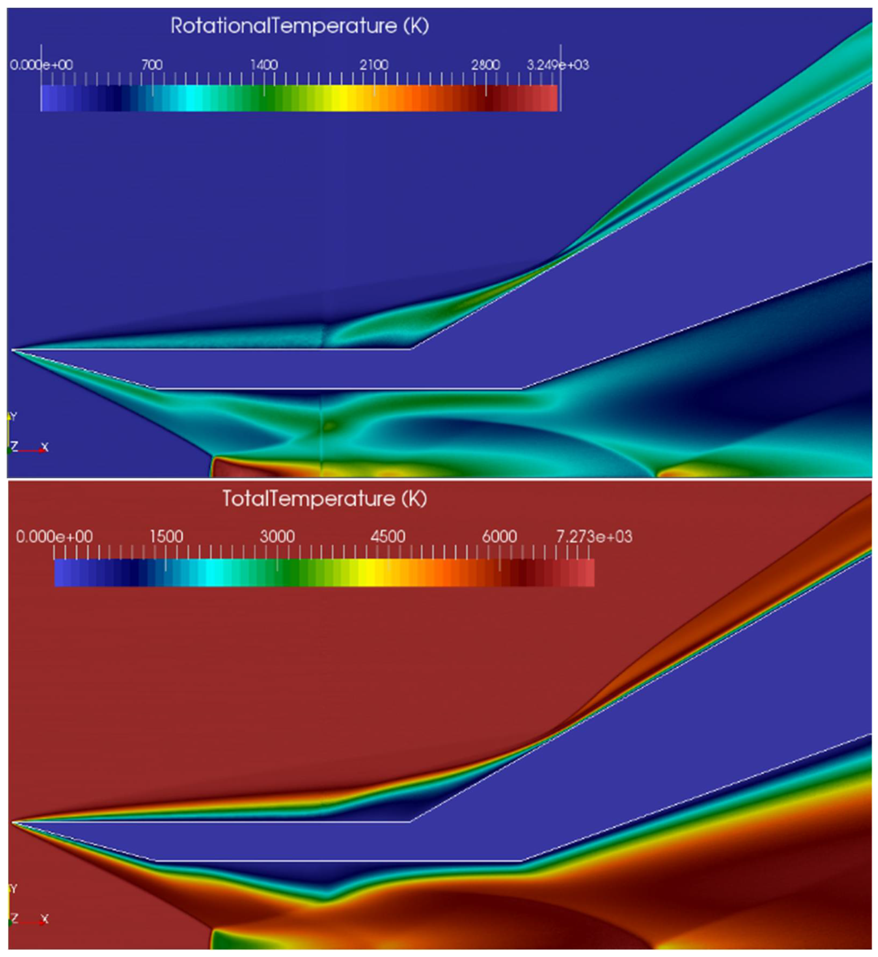
The temperature contours in Figure 3 reveal the necessity of considering the vibrational temperature during simulations, as the temperature values indicate non-equilibrium thermal effects. In all calculations for this case, the surfaces are assumed to have full thermal accommodation for vibrational energy.
Figure 4 (Top) shows the velocity component along the x-axis of the flared cylinder as computed by SPARTA, while Figure 4 (Bottom) presents the velocity component along the r-axis. A barrel shock is observed in the internal area of the cylinder, leading to the formation of a small Mach disk. Additionally, flow separation around the flare region on the external surface of the cylinder is evident. Furthermore, two vortices are formed: one at the separation area on the external surface and another on the internal surface of the cylinder.
Figure 5 (Top) illustrates the static pressure distribution on the surface of the flared cylinder, while Figure 5 (Bottom) shows the heat transfer rate distribution. It is important to note that these results are based on 2D-axisymmetric simulations.

3.2. A Mach 15.6 Flow over a 25/55-Degree Biconic

In this case, the flow around a 25/55 degree biconic geometry is examined. This geometry, along with the flared cylinder geometry examined in the previous section, are the two basic axisymmetric configurations proposed by the NATO Research Technology Organization in collaboration with Working Group 10 [30,31]. This particular test case was chosen due to the complex interactions resulting from the hypersonic flow around the body. Various attempts have been made in the past, using both continuum and particle-based (DSMC) formulations for the simulation of several CUBRC experiments [32,33,34]. Judging from the simulation results from continuum and DSMC solvers, several significant findings have been identified. The first finding is that for DSMC simulations of the CUBRC biconic test conditions, coarse grid solutions do not predict the correct details of the separation area [35]. A second finding is that DSMC and continuum simulation results for the heating rates upstream of the separation area can differ by as much as 33%, as discussed in [29], for laminar flow around either sharp or blunted cones at a zero degree angle of attack.
The geometry of this test case comprises two cones, one with a half angle of 25 degrees and a second one with a half angle of 55 degrees. The geometry details are presented in Figure 6. This geometry produces strong shock interactions in hypersonic speeds because the attached shock from the first cone interacts with the detached bow shock of the second cone. Moreover, the outer shocks are modified by separation and reattachment shocks. The flow conditions are described in Table 4 and the simulation parameters for this test case are shown in Table 5.
Due to complex shock and boundary layer interactions developed during the simulation in this case, in order to capture accurately the physical properties of the flow, serious attention should be given to the grid generation procedure. The computational domain extends from 0.02   m to 0.2   m in the x-direction, and from 0   m to 0.5   m in the r-direction. Three different grids were used for this test case. The first grid is a uniform grid consisting of 870 × 870 cells in the x- and r-directions, respectively, referred to as “Uniform”. The second grid, referred to as “Refined_Grid_1”, also comprises 870 × 870 cells, but includes a refinement zone starting approximately 5 cm after the biconic’s leading edge, continuing to the end of the biconic. Within this refinement zone, each cell is subdivided into 2 × 2 smaller cells. The third grid, denoted as “Refined_Grid_2”, incorporates the refinement zone of “Refined_Grid_1” and adds another refinement zone, beginning 9   c m from the leading edge and extending to the end of the biconic. The cells within this additional refinement zone are further subdivided into 2 × 2 smaller cells. To accurately capture the flow characteristics, 35 million particles were used in the simulations. For this case, two different models exist: one with a blunt nose and another with a sharp edge [36]. In this work, only the model with the sharp edge was considered (Figure 6).
As noted in [29], the flow stabilizes within approximately one millisecond for this specific case. Therefore, the flow simulation is extended beyond a millisecond of physical time to eliminate any numerical artifacts that may be generated during the transient phase of the flow.
Figure 7 compares the computed heat transfer along the surface of the body, using different grid densities, to the available experimental data and simulation results from the dsmcFOAM [37] and DS2V [29], as well as results obtained by the SBT collision model by Goshayesi et al. [38]. The corresponding results for surface pressure are shown in Figure 8. These comparisons highlight the significant impact of proper grid refinement and grid size on the accuracy of simulated results. Although costly, a grid-dependency study is essential to ensure the accuracy of the computational procedure. The initial “Uniform” grid produced reasonable results for the first half of the biconic, but generated unphysical results in the flared region, due to the steep flow gradients caused by shock–shock and shock–viscous interactions. The second grid (“Refined_Grid_1”) generally produced better results, although the results around the flow separation region remained unrealistic. The third grid (“Refined_Grid_2”) showed improved results, except for the end of the flared region. This inaccuracy indicates the steep flow gradients in that area, suggesting the need for an even more refined grid for a portion of the biconic’s horizontal area. In this test case, the SPARTA simulation results are also compared with those obtained from the dsmcFOAM solver [37], which uses an unstructured grid, the DS2V solver [29], and a solver using the simplified Bernoulli trials (SBT) collision selection methodology [38]. The latter has a very good agreement with the experimental results, especially in the 25-degree part of the cone. All results shown in the next Figure 9, Figure 10, Figure 11, Figure 12 and Figure 13 were obtained using “Refined_Grid_2”, as this was the most accurate grid.
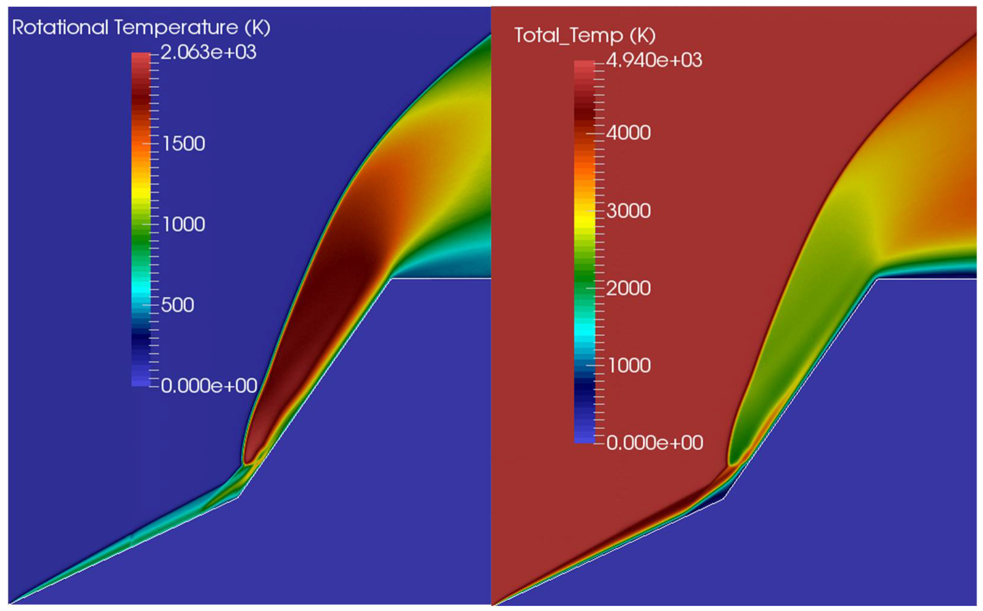
Figure 9 presents the contours of the velocity components in the x- and r-directions, while Figure 10 shows the velocity contours (Left) and the number density contours (Right). Figure 11 displays the contours of the rotational temperature (Left) and total temperature (Right). These figures illustrate the complex physical phenomena occurring near the surface of the biconic body, including the shock–boundary layer and shock–shock interactions.
As shown in Figure 12, an oblique shock forms very close to the surface of the first cone. A shear layer is generated behind this shock on the cone’s solid surface, leading to flow separation at the transition from the first to the second conical angle. Over the separation region, a larger-angle separation shock is formed, accompanied by a contact discontinuity that delineates the recirculation zone from the higher velocity region between the recirculation zone and the separation shock. In front of the second, larger cone, a bow shock originates at the end of the separation shock. A transmitted shock, which then interacts with the solid surface, is also formed and meets the bow shock and separation shock at a common triple point. Behind the transmitted shock, a wavy shear layer develops, with a contact discontinuity (vortex sheet), separating this layer from the nearly uniform flow behind the bow shock. A detailed discussion of the physical phenomena in this test case can be found in [39].
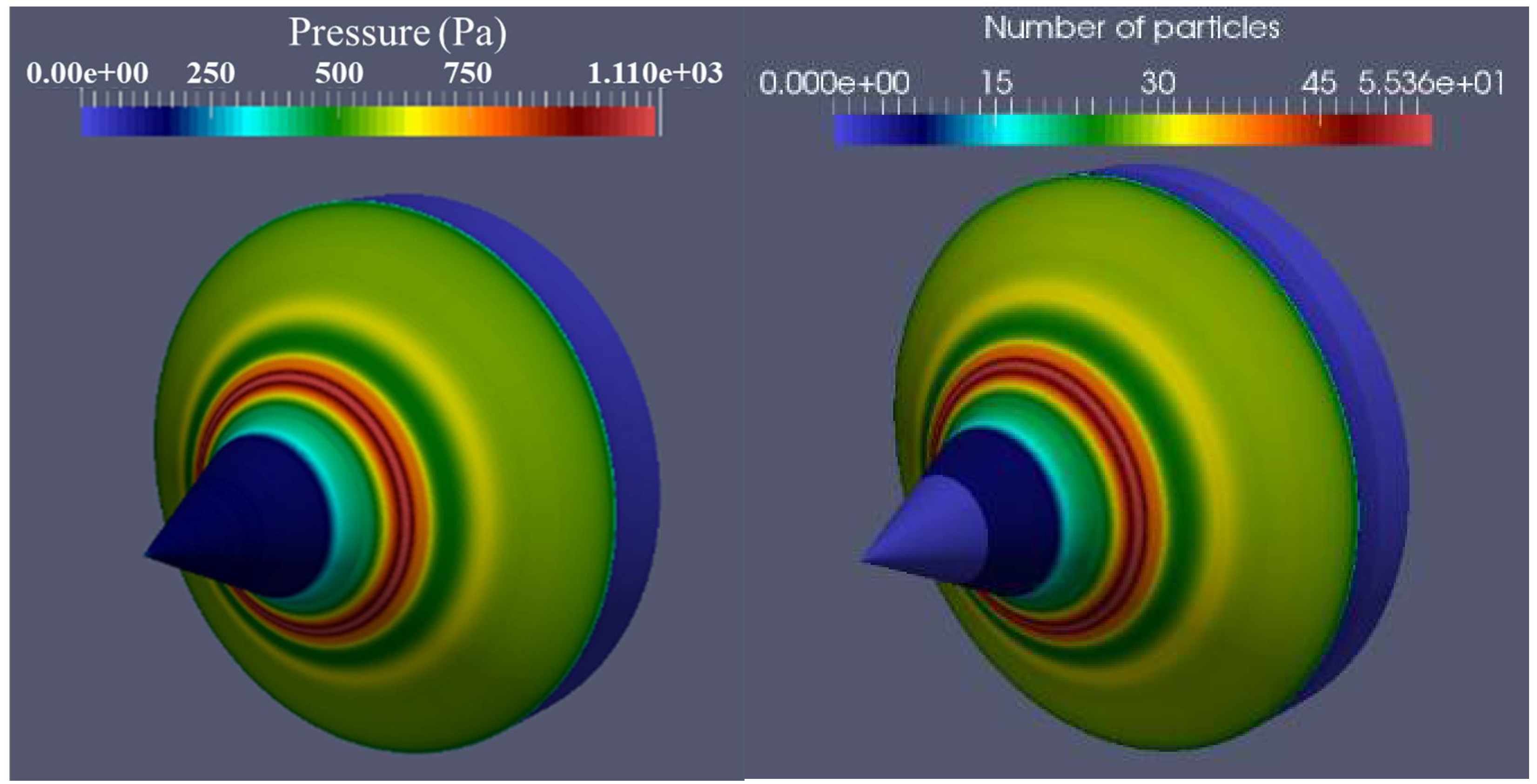
Figure 13 (Left) shows the contours of static pressure on the surface of the biconic, while Figure 13 (Right) displays the corresponding contours of the number of particles hitting the surface elements of the grid. As anticipated, these two contour maps are similar, as static pressure is the macroscopic quantity that results from the particle collisions with the solid surface of the body.

4. Conclusions

In this Part B of the work, we initially presented some of the most well-known projects related to the development of hypersonic vehicles, predominantly originating from the USA. This is unsurprising, given the extensive history of scientific research on hypersonic flight in the country. Continuing the assessment of the DSMC code SPARTA, we considered two additional axisymmetric test cases tailored to hypersonic vehicle development. These cases incorporate physical phenomena, such as shock–shock and shock–viscous interactions, which are characteristic of hypersonic vehicles. Axisymmetric test cases were chosen because they require significantly fewer computational resources compared to three-dimensional simulations, while still capturing the essential geometrical and flow characteristics typical of hypersonic applications. The first test case involves flow through and around a flared cylinder, while the second test case examines flow around a biconic, both under rarefied hypersonic flow conditions. The hollow section of the flared cylinder case exhibits flow phenomena similar to those found in ramjet and scramjet engines, which are used for hypersonic vehicle propulsion. The double-cone test case produces strong shock–shock interactions due to the angle change between the first and second cones. For both cases, grid density was crucial in accurately capturing the physical phenomena and matching the corresponding experimental data. Despite the high demands of simulating rarefied hypersonic flows, the SPARTA solver demonstrated its capability to perform with good accuracy and efficiency.

Author Contributions

Conceptualization, A.K. and I.K.N.; methodology, A.K. and I.K.N.; software, A.K.; validation, A.K. and I.K.N.; resources, A.K.; writing—original draft preparation, A.K.; writing—review and editing, I.K.N.; visualization, A.K.; supervision, I.K.N.; project administration, I.K.N.; funding acquisition, I.K.N. All authors have read and agreed to the published version of the manuscript.

Funding

Part of this work was funded by the Integrated Air and Missile Defence Centre of Excellence (IAMD COE) (CONTRACT 22-04) and any intellectual property resulting from the work covered by this will be the property of the IAMD COE. This paper reflects only the IAMD COE policies and its author(s)’ positions, and it is not intended to create any legal obligations; nor does it reflect NATO’s policies or positions, or engage NATO in anyway.

Data Availability Statement

The data presented in this study are available on request from the corresponding author due to the fact that this project was funded by NATO IAMD-COE, and sharing the data requires their explicit permission.

Acknowledgments

The authors would like to thank Michael Gallis (Sandia National Laboratories) for all the thoughtful technical discussions regarding SPARTA kernel.

Conflicts of Interest

The authors declare no conflicts of interest.

References

  1. Acton, J.M. Silver Bullet? Asking the Right Questions; Carnegie Endowment for International Peace: Washington, DC, USA, 2013. [Google Scholar]
  2. Speier, R.H.; Nacouzi, G.; Lee, C.A.; Moore, R.M. Hypersonic Missile Nonproliferation: Hindering the Spread of a New Class of Weapons; RAND Corporation: Santa Monica, CA, USA, 2017; Available online: https://www.rand.org/content/dam/rand/pubs/research_reports/RR2100/RR2137/RAND_RR2137.pdf (accessed on 30 July 2024).
  3. Besser, H.L.; Goege, D.; Huggins, A.; Shaffer, D.; Zimper, D. Hypersonic vehicles-game changers for future warfare. Transform. Jt. Air Power J. JAPCC 2017, 17, 11–27. [Google Scholar]
  4. Kh-47M2 Kinzhal. Missile Threat, 19 March 2022. Available online: https://missilethreat.csis.org/missile/kinzhal/ (accessed on 30 July 2024).
  5. Judd, D.J. Biden Confirms Russia’s Use of Hypersonic Missiles in Ukraine. CNN, 22 March 2022. Available online: https://edition.cnn.com/europe/live-news/ukraine-russia-putin-news-03-21-22/h_38fe9317803ffd4f7cafe92e6bb53c1c (accessed on 30 July 2024).
  6. Novichkov, N. Russia Announces Successful Flight Test of Avangard Hypersonic Glide Vehicle. Janes, 3 January 2019. Available online: https://www.janes.com/osint-insights/defence-news/russia-announces-successful-flight-test-of-avangard-hypersonic-glide-vehicle (accessed on 30 July 2024).
  7. Panda, A. Introducing the DF-17: China’s Newly Tested Ballistic Missile Armed with a Hypersonic Glide Vehicle. The Diplomat, 28 December 2017. Available online: https://thediplomat.com/2017/12/introducing-the-df-17-chinas-newly-tested-ballistic-missile-armed-with-a-hypersonic-glide-vehicle/ (accessed on 30 July 2024).
  8. Lockheed Martin. Lockheed Martin’s Hypersonic OpFires Missile Has Medium Range Covered. 2020. Available online: https://www.lockheedmartin.com/en-us/news/features/2020/lockheed-martins-hypersonic-opfires-missile-has-medium-range-covered.html (accessed on 30 July 2024).
  9. DARPA. Operational Fires Program Successfully Completes First Flight Test. 2022. Available online: https://www.darpa.mil/news-events/2022-07-13a#:~:text=The%20OpFires%20system%20achieved%20all,to%20initiate%20the%20test%20mission (accessed on 30 July 2024).
  10. U.S. Air Force. Propulsion Directorate Monthly Accomplishment Report; September 2005. Available online: http://www.pr.afrl.af.mil/mar/2005/sep2005.pdf (accessed on 1 October 2024).
  11. Flightglobal. August Failure of Boeing X-51 Likely Due to fin Resonance. 2016. Available online: https://web.archive.org/web/20161014135102/http://www.flightglobal.com/news/articles/august-failure-of-boeing-x-51-likely-due-to-fin-resonance-378080/ (accessed on 30 July 2024).
  12. Boeing. Boeing X-51A WaveRider Sets Record with Successful 4th Flight. 3 May 2013. Available online: https://boeing.mediaroom.com/2013-05-03-Boeing-X-51A-WaveRider-Sets-Record-with-Successful-4th-Flight (accessed on 30 July 2024).
  13. Kay, L. Boeing, Lockheed Win SCIFiRE Hypersonic Weapons Preliminary Design Contracts. Defence World. 2021. Available online: https://www.defenseworld.net/2021/09/02/boeing-lockheed-win-scifire-hypersonic-weapons-preliminary-design-contracts.html (accessed on 30 July 2024).
  14. Freedberg, S.J., Jr. Hypersonics: Army, Navy Test Common Glide Body. Defence Magazine, 20 March 2020. Available online: https://breakingdefense.com/2020/03/hypersonics-army-navy-test-common-glide-body/ (accessed on 30 July 2024).
  15. Army Technology. Advanced Hypersonic Weapon (AHW). 18 July 2022. Available online: https://www.army-technology.com/projects/advanced-hypersonic-weapon-ahw/ (accessed on 30 July 2024).
  16. DARPA. Third Test Flight for DARPA’s HAWC Yields New Performance Data. 18 July 2022. Available online: https://www.darpa.mil/news-events/2022-07-18 (accessed on 30 July 2024).
  17. Little, G. Mach 20 or Bust, Weapons Research May Yet Produce a true Spaceplane. Air & Space Magazine, 1 January 2013. Available online: https://www.smithsonianmag.com/air-space-magazine/mach-20-or-bust-20679807/ (accessed on 30 July 2024).
  18. Airforce Technology. SR-72 Hypersonic Demonstrator Aircraft. Airforce Technology, 30 January 2014. Available online: https://www.airforce-technology.com/projects/sr-72-hypersonic-demonstrator-aircraft/ (accessed on 30 July 2024).
  19. Air & Space Forces. AGM-183 ARRW. Air & Space Forces, 17 May 2022. Available online: https://www.airandspaceforces.com/weapons-platfoms/agm-183-arrw/ (accessed on 30 July 2024).
  20. Defencetalk. DARPA Hypersonic Vehicle Advances Technical Knowledge. Defence Talk, 11 August 2011. Available online: https://www.defencetalk.com/darpa-hypersonic-vehicle-advances-technical-knowledge-36347/ (accessed on 30 July 2024).
  21. Hindustan Times. India successfully tests nuclear-capable Shaurya missile. Hindustan Times, 3 October 2020. Available online: https://www.hindustantimes.com/india-news/india-successfully-tests-nuclear-capable-shaurya-missile/story-fkYlozVJ5oq1MWO26GOwNN.html (accessed on 30 July 2024).
  22. Fry, R.S. A Century of Ramjet Propulsion Technology Evolution. J. Propuls. Power 2004, 20, 27–58. [Google Scholar] [CrossRef] [PubMed]
  23. Amati, V.; Bruno, C.; Simone, D.; Schiubba, E. Exergy analysis of hypersonic propulsion systems: Performance comparison of two different scramjet configurations at cruise conditions. Energy 2008, 33, 116–129. [Google Scholar] [CrossRef]
  24. Bird, G.A. Molecular Gas Dynamics and the Direct Simulation of Gas Flows; Oxford University Press: Oxford, UK, 1994. [Google Scholar]
  25. Bird, G.A. The DSMC Method; Version 1.2; CreateSpace Independent Publishing Platform: North Charleston, SC, USA, 2013; ISBN 9781492112907. [Google Scholar]
  26. Gallis, M.A.; Boyles, K.A.; LeBeau, G.J. DSMC simulations in support of the STS-107 accident investigation. AIP Conf. Proc. 2005, 762, 1211–1216. [Google Scholar]
  27. Gallis, M.A.; Torczynski, J.; Rader, D.; Bird, G. Convergence behavior of a new DSMC algorithm. J. Comput. Phys. 2009, 228, 4532–4548. [Google Scholar] [CrossRef]
  28. Gallis, M.A.; Torczynski, J.R.; Plimpton, S.J.; Rader, D.J.; Koehler, T. Direct Simulation Monte Carlo: The Quest for Speed. In Proceedings of the 29th Rarefied Gas Dynamic (RGD) Symposium, Xi’an, China, 13–18 July 2014. [Google Scholar]
  29. Moss, J.N.; Bird, G.A. Direct Simulation Monte Carlo Simulations of Hypersonic Flows with shock interactions. AIAA J. 2005, 43, 2565–2573. [Google Scholar] [CrossRef]
  30. Knight, D. RTO WG 10—Test cases for CFD validation of hypersonic flight. In Proceedings of the 40th AIAA Aerospace Sciences Meeting & Exhibit, Reno, NV, USA, 14–17 January 2002. AIAA Paper 2002-0433 (RTO-TR-AVT-007-V3). [Google Scholar]
  31. Walker, S.; Schmisseur, J.D. CFD Validation of Shock-Shock Interaction Flow Fields; RTO-TR-AVT-007-V3; NATO Research and Technology Organisation: Brussels, Belgium, 2006. [Google Scholar]
  32. Candler, G.V.; Nompelis, I.; Druguet, M.-C.; Holden, M.S.; Wadhams, T.P.; Boyd, I.D.; Wang, W.-L. CFD Validation for Hypersonic Flight: Hypersonic Double-Cone Flow Simulations; RTO-TR-AVT-007-V3; NATO Research and Technology Organisation: Brussels, Belgium, 2006. [Google Scholar]
  33. Moss, J.N.; Bird, G.A.; Markelov, G.N. DSMC simulations of hypersonic flows and comparison with experiments. AIP Conf. Proc. 2005, 762, 547–552. [Google Scholar]
  34. Wang, W.-L.; Boyd, I.D. Hybrid DSMC-CFD simulations of hypersonic flow over sharp and blunted bodies. In Proceedings of the 36th AIAA Thermophysics Conference, Orlando, FL, USA, 23–26 June 2003. AIAA Paper AIAA 2003-3644. [Google Scholar]
  35. Gimelshein, S.F.; Levin, D.A.; Markelov, G.N.; Kudryavtsev, A.N.; Ivanov, M.S. Statistical Simulation of Laminar Separation in Hypersonic Flows: Numerical Challenges. In Proceedings of the 40th Aerospace Sciences Meeting & Exhibit, Reno, NV, USA, 14–17 January 2002. AIAA paper 2002-0736. [Google Scholar]
  36. Moss, J.N. Hypersonic Flows about a 25° Sharp Cone, NASA/TM-2001-211253; National Aeronautics and Space Administration: Washington, DC, USA, 2001.
  37. Ahmad, A.O. Capturing Shock Waves Using an Open-Source, Direct Simulation Monte Carlo (DSMC) Code. In Proceedings of the 4th European Conference for Aero-Space Sciences (EUCASS), St. Petersburg, Russia, 4–8 July 2011. [Google Scholar]
  38. Goshayeshi, B.; Roohi, E.; Stefanov, S. A novel simplified Bernoulli trials collision scheme in the direct simulation Monte Carlo with intelligence over particle distances. Phys. Fluids 2015, 27, 107104. [Google Scholar] [CrossRef]
  39. Tumuklu, O.; Theofilis, V.; Levin, D.A. On the unsteadiness of shock–laminar boundary layer interactions of hypersonic flows over a double cone. Phys. Fluids 2018, 30, 106111. [Google Scholar] [CrossRef]
Figure 1. Flared cylinder geometry (units in millimeters) [29].
Computation 12 00200 g001
Figure 2. (Top) Heat transfer on the external surface of the cylinder. (Bottom) Pressure distribution on the external surface of the cylinder (LENS Run 11).
Computation 12 00200 g002
Figure 3. (Top) Rotational temperature. (Bottom) Total temperature (LENS Run 11, “Refined_Grid”).
Computation 12 00200 g003
Figure 4. (Top) Velocity component along the x-axis. (Bottom) Velocity component along the r-axis (LENS Run 11, “Refined_Grid”).
Computation 12 00200 g004
Figure 5. (Top) Pressure at the flared cylinder surface. (Bottom) Heat flux on the flared cylinder surface (LENS Run 11, “Refined_Grid”).
Computation 12 00200 g005aComputation 12 00200 g005b
Figure 6. The double-cone geometry [29,36].
Computation 12 00200 g006
Figure 7. Heat transfer computation on the surface of the biconic. The effect of the grid quality on the DSMC simulation results is pronounced.
Computation 12 00200 g007
Figure 8. Static pressure computation on the surface of the biconic.
Computation 12 00200 g008
Figure 9. (Left) Contours of axial velocity component. (Right) Contours of radial velocity component (biconic test case).
Computation 12 00200 g009
Figure 10. (Left) Contours of velocity. (Right) Contours of number density (biconic test case).
Computation 12 00200 g010
Figure 11. (Left) Contours of the rotational temperature. (Right) Contours of the total temperature (biconic test case).
Computation 12 00200 g011
Figure 12. The complicated flow formations near the surface of the body (biconic test case).
Computation 12 00200 g012
Figure 13. (Left) Contours of static pressure on the surface of the biconic. (Right) Contours of the number of particles hitting the surface elements of the grid (biconic test case).
Computation 12 00200 g013
Table 1. Summary of known US hypersonic programs.
Project NameOrganizationTypeMachExpected Date of ServiceStatus
OPERATIONAL FIRES (OpFIRES)DARPAHypersonic glide missile5-Under development
BOEING X-51 WAVERIDERDARPAUnmanned research experimental aircraft5-Under development
Southern Cross Intergrated Flight Research Experiment (SCIFIRE)USA/AustraliaHypersonic cruise missile5Before 2030Under development
Long Range Hypersonic Weapon (LRHW)US ArmyICBM5Before 2023Under development
Advanced Hypersonic Weapon (AHW)DARPAHGV5+Before 2025Under development
Hypersonic Air-Breathing Weapon Concept (HAWC)USASMDC/ARSTRATHypersonic cruise missile5+Before 2025Under development
Hypersonic Technology Vehicle HTV-3XDARPAHGV5–10-Cancelled
SR-72 BlackbirdLockheed MartinHypersonic reconnaissance UAV6Before 2030Under development
AGM-183 Rapid Response Weapon (ARRW)Lockheed MartinHypersonic air-to-ground missile - glide vehicle5+Before 2025Under development
Hypersonic Technology Vehicle HTV-2DARPAHGV20+-Cancelled
Table 2. Flow conditions sets obtained from [29] (flared cylinder case).
Run V   ( m s ) n   ( m 3 ) T , T   ( K ) ρ   ( k g / m 3 ) p   ( P a ) M R e Gas
48-inch Run 7 2073 3.779 × 10 21 42.6 1.757 × 10 4 2.23 15.6 1.37467 × 10 5 N2
LENS Run 11 2484 1.197 × 10 22 95.6 5.566 × 10 4 15.86 12.4 2.08333 × 10 5 N2
Table 3. Computational parameters used in the simulations (LENS Run 11).
V x   ( m s ) n   ( m 3 ) T , T   ( K ) T w   ( K ) T i m e   S t e p   ( s ) Fnum
2484 1.197 × 10 22 95.6 293 2.0 × 10 8 4.4 × 10 18
Table 4. Flow conditions set obtained from [29] (biconic case).
Flow ConditionGas V e l o c i t y   ( m s ) Number
Density
(m−3)
Flow
Temperature
(K)
Surface
Temperature
(K)
CUBRC Run 7 N 2 2072.6 3.78 × 10 21 42.61297.2
Table 5. Simulation parameters (biconic case).
Flow ConditionGas T i m e s t e p   ( s ) Transient
Period
(Timesteps)
Sampling
Period
(Timesteps)
Interval
Sample
Data
CUBRC Run 7 N 2 4.0 × 10 8 250,00027,0002
Disclaimer/Publisher’s Note: The statements, opinions and data contained in all publications are solely those of the individual author(s) and contributor(s) and not of MDPI and/or the editor(s). MDPI and/or the editor(s) disclaim responsibility for any injury to people or property resulting from any ideas, methods, instructions or products referred to in the content.