Abstract
Enhancing resiliency in a power grid system is one of the core mandates of electrical distribution companies to provide high-level service. The power resiliency research community has proposed numerous schemes, to detect, classify, and localize fault events. However, the literature still lacks a comprehensive taxonomy of these schemes which can help advance future research. This study aims to provide a compact yet comprehensive review of the state-of-the-art solutions to fault analysis in transmission power systems. We discuss fault types and several fault-analysis methodologies adopted by relevant research works, propose a novel framework to classify these works, and highlight their strengths and limitations. We anticipate that this brief review would be helpful as a literature review and benefit the research community in choosing suitable techniques for fault analysis.
1. Introduction
Electric power systems have evolved over decades from synchronous machines to renewable energy sources for generating electricity. However, the power grid’s operation has always been challenging because of extreme operational and environmental conditions. In this section, we address the need for power system fault analysis and provide the contributions and structure of this paper.
1.1. Background
Power transmission is the first step to transporting the bulk of power from a power generator to the last mile of a power grid. The transmission system includes many fundamental components such as step-up and step-down transformers, power lines, towers, switches, relays, and reclosers. Figure 1 shows different subsystems of a power grid system. This system is susceptible to many challenges, such as power loss that changes to thermal energy due to conductor resistance (I2R), where I is the current and R is the resistance. That is why the voltage is increased to minimize the resistive loss. Another challenge is the skin effect, where current flows along the outer surface/skin of the cable due to a high frequency. This means that the current flows through a very small portion of the conductor’s cross-section, thereby increasing the resistance. These challenges and environmental factors such as storms, heavy freezing rains, and wild habitat activities contribute to transmission element faults. These could heavily impact customers, such as the recent historic blackouts that hit Texas, USA, in 2021 due to a severe winter storm. Hurricane Sandy is another example that hit the USA in 2012, causing a wide range of damage, hundreds of casualties, and thousands of displaced residents in the great New York area [1].
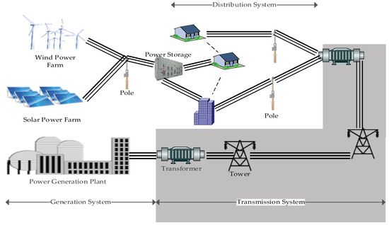
Figure 1.
A schematic of a Power Grid System, where the gray-shaded part represents the transmission system.
The most recent review in this field [2] described different techniques investigated by several researchers for detecting, classifying, and localizing transmission faults. However, it lacks a clear classification scheme and only provides a comparative analysis for fault localization proposals. In [3], the authors employed fault-analysis methods to classify a limited number of relevant previous works. Other studies and surveys classified the works differently, e.g., according to their computational intelligence features [4] as prominent, hybrid, or modern [5].
1.2. Contribution of the Paper
Our contributions relative to the recent research work in the field can be summarized as follows:
- Unlike other surveys, this study provides a deeper insight into the comprehensive and most recent state-of-the-art techniques for academic and industrial research communities;
- We highlight the key challenges presented in the recent literature and summarize the related research work in terms of their strengths, weaknesses, and gaps;
- We provide a novel classification scheme to classify relevant fault-analysis techniques according to the method used and the target task (i.e., detection, classification, or localization).
1.3. Review Methodology
In Figure 2, we present a flowchart to provide a visual connection of the different components of our methodology. While each component is described in detail in the subsequent sections, this flowchart shows our review methodology as a whole, emphasizing the integration between its components.
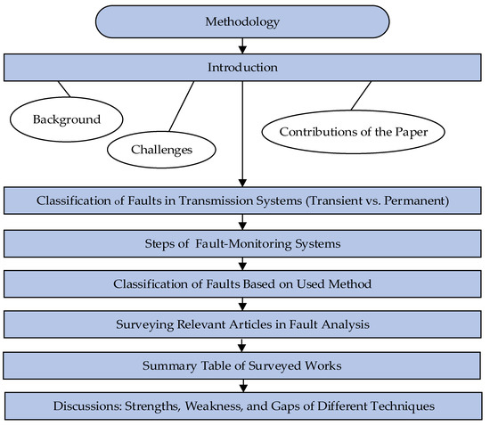
Figure 2.
The process flow of our review methodology.
1.4. The Paper Outline
The structure of this paper is as follows: Section 2 provides a classification of faults in a transmission system. Fault analysis techniques are discussed in Section 3; a summary of these techniques based on the method used for fault analysis and some key points is provided in Section 4. Finally, we conclude the paper in Section 5.
2. Fault Classification and Monitoring
A transmission power system encounters different types of faults, classified into transient and intransient, as shown in Figure 3. The former is not usually visible to power technicians and is difficult to locate; the power can go off temporarily and then be restored. Examples of transient faults are temporary contact of a tree to any transmission phase, animals like birds contacting power lines, lightning strikes affecting the transmission system, and phases clashing due to storms. The latter type, i.e., intransient, is permanent until power engineers fix it. It can be either open or short circuited [6,7].
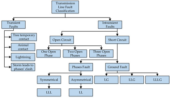
Figure 3.
Classification of faults in overhead transmission lines.
In contrast to short-circuit faults, open-circuit faults occur when one or more lines malfunction or break without making contact with any external objects or ground. This fault produces a very high voltage in some parts of the transmission system, causing voltage instability, which may develop into short-circuit faults and pose a danger to humans and animals [8].
On the other hand, short-circuit faults result from abnormal contact of low impedance between two parties of different potentials due to random and unpredictable events such as severe weather conditions, animals, supply/demand unbalancing, and aging. Consequently, power returns to the source and does not reach the distribution system, causing a high current to flow through the transmission system to an object/ground, damaging the equipment. Therefore, transmission power faults can be further classified into phase faults or ground faults. Phase fault refers to the case when power lines contact each other or another object but not the ground. If the fault affects all three phases equally, the fault is symmetric (LLL). Otherwise, it is asymmetric (LL). On the other hand, a ground fault occurs when any transmission phase contacts the ground. So, it is either one line to the ground (LG), two lines to the ground (LLG), or three lines (LLLG) [9].
Power grids are highly fragile systems, and many factors impact the performance and quality of service. Therefore, it is imperative to embed fault resiliency and self-healing processes in power grids to promptly locate the faults, repair them, and restore the power service [10]. One of the pillars of resilient systems is having data about different system components, processing it, and drawing an instantaneous picture of their state. Unfortunately, legacy power grids lack both a real-time measurement of their state and a direct way to assess the parameters of a power grid system such as active current, voltage, phasors, etc. However, deploying sensors enables legacy power grid systems to cope with this drawback and act proactively rather than reactively to prevent faults. Furthermore, the power in a transmission line can flow in either direction according to the load at the two ends, and hence the information from the endpoints of transmission lines is necessary to develop a holistic picture of the state of a transmission system.
Historically, the topology of a transmission system has been used alongside electricity laws to estimate various power parameters, such as voltage values at several interconnection points of the power system. The control center calculates these parameter readings to generate a partial picture of the system’s state. As a result, faults can be detected. However, the fault itself can’t be accurately localized using minimal measurements. It is usually spotted and inspected visually, which is time-consuming [11].
In the early 1980s, relays were used to detect and localize faults in power transmission lines. Once a fault occurs, two surges of power are generated by that fault. These surges flow to relays placed at the two ends of the power line. Thus, a fault is detected. The time difference between receiving these surges is measured to calculate the fault location. This method is simple and easy to apply, using a wavelet transform to signals [12]. Still, it suffers from drawbacks such as localization inaccuracy due to the lack of capturing an accurate measurement of the time difference between the two surges, given that the signals travel at the speed of light (i.e., 3 × 10⁸ m/s). Indeed, a slight drift in time difference will significantly impact the localization of the fault place. For instance, 1 µs (microsecond) of time difference drifts the estimated location of the fault by 300 m. Recent research has overcome the inaccuracy of the wavelet transform by combining it with other tools such as entropy-based methods to identify different faults’ time-frequency characteristics. Hence, it accurately and quickly determines the fault type or disturbances with sufficient noise tolerance [13].
Fault-monitoring systems usually target three tasks: detection, identification or classification, and localization, as shown in Figure 4.
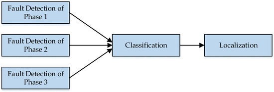
Figure 4.
Steps in fault-monitoring systems. Any combination of faults in line phases could exist.
Fault detection refers to the process that shows instability in the transmission system and depends on collecting different system state measurements such as voltage, current, and phases’ differences. The measurements from all phases can indicate whether or not there is a fault in a power system. The second step is responsible for classifying and identifying fault types. Monitoring of all transmission lines allows better identification of fault types. This step is critical for technical staff to understand the issues they are dealing with and to gather all of the necessary equipment to solve them.
The last step is localizing the fault, which refers to the process that ends up finding/locating the fault place. Fault localization utilizes the measurements from the detection step to locate faults accurately.
3. Fault Analysis Techniques
This paper provides a novel classification scheme to classify fault analysis techniques by the methods used and their tasks (i.e., detection, identification, and localization). Figure 5 shows the classification of fault analysis techniques by the methods used. A technique can either use conventional or modern approaches to analyze faults.
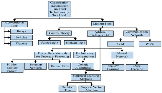
Figure 5.
Classification of fault analysis techniques based on the method used.
A fault is temporary if it is cleared after breaker reclosing and is a permanent fault otherwise [14]. A permanent fault requires power technicians to locate and repair the faulted line section to restore power service. In conventional methods, protective relays, placed at both ends of a transmission line, sense the fault immediately and isolate the faulted line by opening the associated circuit breakers [15]. Distance relays are fast and reliable ways to locate the fault area. However, they fall short of providing accurate fault localization. In addition, it is difficult to identify and classify faults using relays, triggering the need for other techniques to overcome this drawback.
A wavelet-based technique is effective for analyzing transient power faults. It is mainly effective for fault detection and localization [16,17,18,19,20]. Improving fault detection and location accuracy can be achieved by using the maximum wavelet coefficients (WCs) of the frequency and voltage signals under fault disturbance and investigating the relationship between the WCs and power variation. Fault detection, identification, and location usually need to be solved as a unified problem in power systems. However, most methods discussed in previous literature focus on one or two aspects and cannot solve all three problems simultaneously. It can be foreseen that a multifunctional approach, which can achieve fault detection, identification, and localization, has the potential for a wide range of applications in power systems.
T. Takagi et al. [21] developed an equation based on the electrical equations of the loop formed by a single-phase to ground resistive fault, using only the wavelet readings from one end of the transmission line. They localized faults in a transmission line by separating the circuit into two equivalent circuits: one prior to the fault and the other during the fault. Each of these gives an equation about the current and the voltage. On the other hand, modern techniques can be classified into control theory, Artificial Intelligence (AI), and communication networks.
3.1. Control Theory
Control theory refers to the field focusing on controlling dynamic systems and ensuring the stability of the operating systems without delay. Next, we discuss fuzzy logic and Boolean logic as well-known methods in control theory.
3.1.1. Fuzzy Logic
Fuzzy logic (FL) is an extension of a multivalued logical system. This control theory class follows an intuitive approach with less complexity [22]. The truth variables are real values between 0 and 1, where 0 means very false and 1 means very true. FL can model nonlinear functions and simplify the control of dynamic systems. Natural languages, control systems, and clustering in networks are some of the applications of FL. FL has also been used in power systems for control and analysis [23,24,25,26]. For instance, the impact of the lightning strike on a fault location in a transmission power system was determined using FL [27]. The authors found that the rate of false or missed alarms is minimal for the FL method, while FL-based and SCADA methods have comparable performance for lightning strike trips, and the correlations of 100 km line trips are equivalent for the conducted experiment throughout the time interval.
The authors in [28] used a fuzzy inference system to detect, classify, and localize a fault section in combined transmission lines and underground power cables. Their approach depends on ten adaptive networks based on a fuzzy inference system (ANFIS), using post-fault voltage and current measurements. ANFIS1 is used to classify the fault type. The fundamental frequency amplitude of the three-phase currents plus the neutral current will be the input for ANFIS2. The output has the formats A, B, C, and G, representing the three phases and the ground. Any output A, B, or C close to 1 refers to a fault in that phase. Similarly, if G closes to 1, the fault involves the ground. The four short-circuit fault types, namely LL, LLL, LLG, and LG, can be overhead or underground. Thus, the eight ANFISs are trained for each type to locate the faulty section. To classify overhead and underground faults, sampled values (within one cycle) of a post-fault peak can be used to estimate the inputs of ANFIS The authors tested their proposed algorithm to ensure accuracy, conducting several scenarios including short-circuit fault types, fault inception angles, and impedances. The maximum location error of a faulty section is below 0.07%. However, considering these parameters increases the complexity and learning time for different training sets.
3.1.2. Boolean Logic
Boolean logic is simpler than fuzzy logic as the variables have truth values of true or false. It provides only a binary value representation: 0 for false and 1 for true. This representation is different from fuzzy logic, where values can be any real value between 0 and 1, and is also different from ordinary algebra, where the variables can have any numerical value [29]. The three main operators in Boolean logic are conjunction (˄), disjunction (˅), and negation (¬). Boolean logic played a significant role in the digital revolution, especially in digital circuit design and information communication. Boolean logic applications such as error propagation modeling and computational geometry are applied to approximately a molecular surface area [30]. Boolean logic was implemented in power systems analysis along with other methods to diagnose faults [31].
3.2. Artificial Intelligence
Next, we discuss AI-based techniques, including probabilistic methods for uncertain reasoning, evolutionary computation, statistical learning methods, and neural networks.
3.2.1. Probabilistic Methods for Uncertain Reasoning
There are many probabilistic methods for uncertain reasoning and include the hidden Markov model (HMM), Bayesian networks, and Kalman filter. HMM is a statistical method based on the Markov process with hidden states. Using HMM, researchers seek to recover the sequence of hidden (unobserved) states from the observed generated data. There are many applications of HMM, such as speech recognition, protein structure prediction, genome-sequence analysis, and image classification [32]. HMM has been used recently in the fault diagnosis of power systems, for example, to detect power faults that lead to islanding in a smart grid [33,34]. In [35], the authors formulate the problem of detecting a transmission line fault using HMM. They produced a probabilistic estimation of the transmission line status using inference and particle filtering. This approach is robust to measurement errors of phasor measurement units (PMU). The proposed HMM-based algorithms outperform other algorithms for noise levels of 0.1, 0.15, and 0.2 with detection percentages of 99, 95, and 91, respectively. However, using HMM has two drawbacks: the expensive computational complexity and the high amount of memory required, posing a scalability issue. Although this approach claims to reduce computational complexity, it is clear that there is a tradeoff between computational complexity and fault detection accuracy.
Similarly, Bayesian networks (BNs) have been used successfully to create consistent probabilistic representations of uncertain reasoning in many fields, such as audio-visual speech recognition, medical diagnosis from partially correct data, biological interactions, and many others [36]. BNs also locate faults in transmission power systems [37,38]. Fault diagnosis BN-based models can work with uncertain or incomplete data related to a power fault analysis system [39]. In [39], the initial parameters of the BN depend on historical inputs from domain experts, which are further refined using an error backpropagation. The proposed system uses the following evaluation criteria: (1) if the fault belief degree of an element is >0.7, this element is faulty; (2) if the degree of an element is in the range of [0.15–0.7] inclusive, this element may be faulty; and (3) if the degree of an element is <0.15, this element is normal. This approach is efficient, scalable, and independent of network topology; hence, it can be applied to any large-scale transmission power system. However, there are some concerns regarding the computational cost of running this approach.
On the other hand, the Kalman filter (KF) is an optimal estimation algorithm for variables of interest that cannot be directly measured. It also assesses the state of the system from indirect and noisy measurements. KF is used in many ways, such as spacecraft to estimate their altitude and localize objects such as mobile robots and driverless vehicles [40]. In many domains, KF has also been adopted in many research studies concerning power systems [41,42,43]. Recently, Neto et al. [44] presented a KF-based solution to locate faults in transmission lines where magnetic fields produced by current signals are measured using magneto-resistive sensors installed at transmission line terminals. The proposed solution uses the extended KF (EKF) to process these measurements and employs a travelling wave approach to localize the fault. The proposed algorithm performs approximately 250 multiplications and 400 additions for a new sample provided by the sensors.
Consequently, accuracy is limited by the sampling frequency. The minimum and maximum localization errors of the proposed solution are 0 m and 107 m, with an average fault location of 26 m and a standard deviation of 16 m, fault resistance of 229 Ω and a fault inception angle of 245°. Furthermore, this approach requires highly synchronized clocks to calculate the travelling wave time and achieve accurate localization.
3.2.2. Artificial Neural Networks
An artificial neural network (ANN) is a powerful tool that has been used for a long time in many applications spanning pattern recognition, feature extraction, noise reduction, and prediction. An ANN is trained, usually in a supervised manner (each set of inputs is associated with the desired output), by feeding it with many input examples. Once the ANN is sufficiently trained, it can solve different test scenarios than those it was trained with. It can even generalize the learning by producing solutions to new data that have not been part of the training phase [45]. Figure 6 shows the simplest form of 1-perceptron ANN, where and represent the input and weight, respectively. Sigma is the learning function followed by the activation function, which ends with the output. ANN-based techniques for faulty transmission lines can handle one or more steps of fault diagnosis. In other words, ANN-based techniques detect, classify, or localize the fault. For detecting a fault, the output is binary, indicating whether there is a fault or not, while classifying the fault type requires more outputs. On the other hand, a fault location can be referred to using distance measurements from a specific line terminal or a block/section where the fault has occurred. The former requires only one output, while the latter may require multiple outputs to identify the fault block/section.
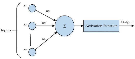
Figure 6.
1-perceptron ANN.
ANN can be either shallow or deep. Most fault analysis techniques follow a shallow learning approach [46,47]. Several research papers have employed ANN for fault analysis in the power grid [48,49,50,51]. A feed-forward 3-layer ANN has been designed to estimate the resistance and location of a faulty 3-phase transmission line using voltage and current readings of a single terminal [52]. Similar to Takagi’s method [21], Ref. [52] it requires the voltage and current parameters prior to and during the fault. Each value of these two parameters has two parts: real and imaginary. The total number of inputs for ANN is 15, where the number of hidden nodes is 8, 11, or 12 for weak, medium, or strong source impedance, respectively. The outputs are the fault resistance and the fault location in terms of distance from the used terminal of the transmission line. The result shows the high performance of this technique with 1% precision for the fault location and 3% for the fault resistance. Although this result outperforms the conventional methods, it is unclear whether or not the technique in [52] will hold for high values of resistive fault with changes in source impedance.
On the other hand, deep learning is a relatively new dimension in ANN, with the most recent breakthrough in 2006. Deep learning enables unsupervised feature learning, pattern analysis, and classification. The fundamental principles of deep learning can be summarized as follows [53]: (1) Unsupervised learning is used to pre-train each layer; (2) unsupervised training of one layer at a time, on top of the previously trained ones, where the representation learned at each level is the input for the next layer; and (3) supervised training used to fine-tune all the layers (in addition to one or more additional layers dedicated to producing predictions). Recently, attention has been drawn to applying deep learning to fault diagnosis in a power transmission system [54,55,56,57]. In [49], the authors developed a technique based on deep learning where data is extracted from a power system control center and preprocessed before the deep learning network training. Then auto-encoders are used to process the data, and hidden features are evaluated to conclude the existence of the fault. If a fault is detected, the second step is to classify the fault type, where trained stacked auto-encoders are used for training a deep learning network. For proper parameter setting, the diagnosis accuracy rate is more than 80%. This means the number of hidden layers and epochs influences the accuracy rate of diagnosis. For example, large numbers of hidden-layer units and epochs might enhance the accuracy, but would also cost more time for training, influencing on-the-fly fault diagnosis.
Feature Extraction
Feature extraction is a major step for fault analysis in power grids, without which most fault-analysis methods may not be set up correctly. AI-based techniques use the extracted features for training AI models. In power grid analysis, current and voltage measurements are usually collected in samples and forwarded to a feature extraction technique. The extracted features are then used to detect, classify, and locate faults. For example, frequency measurements could be collected and decomposed in a time-frequency form to extract time-frequency features. The extracted features can then be used by clustering techniques to partition the power grid and determine the fault location [58]. The scope of this topic is large and diverse, and we highlighted its significance and application multiple times in the text.
3.2.3. Evolutionary Computation
Evolutionary computation is a field based on trial-and-error with stochastic optimization. Perhaps, genetic algorithms (GA) are the most common class in the larger category of evolutionary computation. They are inspired by natural selection theory [59], involving the following steps:
- (1)
- An initialized population of potential solutions is randomly generated;
- (2)
- The fitness function is evaluated;
- (3)
- If it satisfies the optimization/termination criteria or constraints, the best output is generated; otherwise the process is terminated;
- (4)
- The population is subjected to natural selection in order to select the best-fitting parents for breeding;
- (5)
- To create a new generation, genetic operators such as crossover and mutation are used;
- (6)
- Go to step number (2).
Crossover or recombination combines two or more parts of candidate solutions to breed a new one. On the other hand, mutation performs local modifications to a solution [60]. The last two steps, selection and generation, are iteratively run until the best candidate solution is selected.
Researchers have employed GAs to analyze faults [61,62] and solve other problems in power grids, such as managing microgrid energy [63] and achieving an optimal design of distribution powerlines [64]. GA can be employed to locate faults in transmission lines using the data from the two-terminal transmission line [65]. The authors in [65] utilize a distributed time-domain model of a power transmission line to derive a fault location formula. The objective function reflects the relationship between the derived voltages from both terminals. Therefore, the goal of the proposed GA is to minimize the location error by collecting synchronous measurements of post-fault voltage and current from the two ends of the line. For a fault happening 100 km from the S terminal, the proposed GA presents a fault distance of 99.882 km from the S terminal, which is very close to the actual fault point (i.e., −0.118% error of fault location).
3.2.4. Statistical Learning Methods
Statistical learning methods include decision tree (DT) and support vector machine (SVM). DT is a graph with no cycles, a commonly used predictive statistical model, especially for classifications [66]. It contains decisions and possible outcomes. Safety evaluation and classifiers on private databases are some applications of DTs [67]. A DT-based method has been developed to classify a fault type in a single-circuit transmission line [68]. The DT is trained using the odd harmonics (up to the 19th) of the measured signals. Although the result is promising, with a classification accuracy of a cycle’s quarter, the reliability is an issue as the training inputs could be erroneous. Furthermore, DT methods usually pose computational complexity, which has not been included in [68].
Likewise, SVM is a classification technique that belongs to statistical learning theory. One of the most effective linear classifiers uses kernel tricks to create a nonlinear classifier [69]. It is a supervised learning method to train machines to learn independently without explicit static programming instructions. Applications of SVM cover many fields such as medicine to classify, for instance, cancer tissue, financial forecasting, and text classification [70], among many others. Researchers have used SVM successfully in fault analysis in power systems [71,72,73,74,75]. SVM can also be used to localize faults in power transmission systems with high accuracy (up to 99%) [76].
3.3. Communication Networks
3.3.1. Global System for Mobile Communications (GSM)
GSM is a telecommunication standard developed by the European Telecommunication Standard Institute (ETSI). It is considered the second generation (2G) of cellular networks used by mobile devices [77]. GSM has been used in power fault analysis [78,79]. For instance, in [79], a technique has been proposed to detect and classify a faulty transmission line. The proposed system consists of protective equipment such as relays, switch breakers, reclosers, voltage sensors, an 8-bit microcontroller, a GSM module, and a LED display. Since the micro-controller works on a 5 V voltage level and serial communication with the computer system works on a 12 V voltage level, a MAX232 IC is used to boost the signal from 5 V to 12 V. The sensed fault signal is delivered to the microcontroller to analyze the characteristics of the signal in terms of current and voltage readings. The microcontroller will detect and classify the fault once it occurs. GSM will be used to send a message to the person in charge of any existing fault. Finally, the microcontroller sends a signal to relays and switch breakers to isolate the faulty section.
3.3.2. Wireless Sensor Networks (WSNs)
A WSN comprises sensor nodes with sensing functionalities to monitor physical properties such as voltage, humidity, temperature, pressure, and moving objects. A sensor has a small processor, a battery as a power supply, memory, and a short-range wireless transceiver [80]. The collected sensed data is typically propagated towards the base station (BS) in a multi-hop fashion to provide the whole picture of the target region/object. For example, Figure 7 shows a path of sensed data from sensor nodes, aggregated at BS, then transmitted to the end-user via a communication medium such as TCP/IP protocols or GPRS.
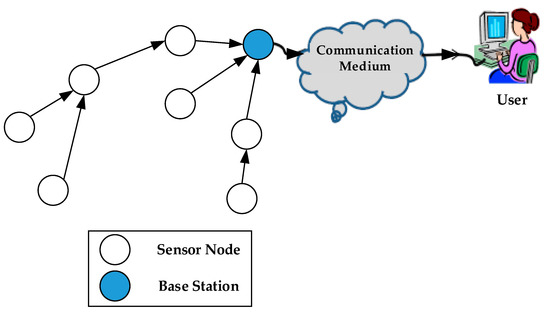
Figure 7.
An illustration of a data flow in WSN.
Since WSN is one of the leading IoT enablers, researchers often use the term IoT to indicate WSN [19,81]. WSNs have been applied to smart buildings, smart vehicles, health care, environmental studies, security, tracking objects, and agriculture [80]. They can also play a key role in monitoring the status of transmission lines in a real-time manner [82,83]. For example, [82], a WSN-based system has been proposed to monitor power transmission lines. The proposed system can be divided into two subsystems: Monitoring and operation. In the monitoring subsystem, heterogeneous sensors with different vision and magnetic induction capabilities are deployed on transmission towers. These sensors collect data on a real-time basis and send it to the operation subsystem. The collected data is transmitted wirelessly through the transmission line with up to 138 kV of power. Thus, there is no need for cellular or optical communication to deliver the sensed data to the operation subsystem for analysis. The results are displayed through a graphical user interface, showing real-time monitoring and fault detection. The display shows carbon monoxide (parts per million), temperature (Celsius), pressure, span and structure images, and luminosity.
4. Summary of The Analysis Techniques
Table 1 summarizes the fault analysis techniques. In addition to the remarks, the third column denotes whether the corresponding technique employs one terminal or two transmission line terminals to achieve its objective/task of fault analysis. The following are some key points that we make regarding these techniques: (i) There is an increasing number of proposals that employ modern techniques such as ANN and machine learning (ML) methods. However, even this sophisticated tool can fail to catch some transient events. For example, the voltage drop due to a generator’s malfunction or overloading usually impacts the three phases uniformly. ANN is usually trained to detect the abnormal voltage and current differences between these phases due to a fault in one or more of them. Therefore, there is a need for further feature engineering to reflect on special transient events; (ii) sensors are vital devices for data acquisition for almost all modern technologies. Thus, cybersecurity is of paramount importance to grid operators. It is critical because cyber attackers could manipulate the readings of voltage and currents to be perceived as normal while, in fact, there is an imminent failure (i.e., increase the false negatives) or vice versa. During normal loading, current and voltage measurements collected by sensors are almost balanced. However, these measurements fluctuated in faulty incidents, indicating an unbalanced loading state; and (iii) localization-based techniques that utilize the time difference of travelling signals usually face accuracy issues due to the inaccuracy of time measurements. Furthermore, techniques that collect power-related readings at the two ends of power lines provide more accurate fault localization than impedance-based techniques.

Table 1.
Summary of the analysis techniques concerning the methods considered in the surveyed works. It illustrates the tasks these techniques perform (i.e., detection, classification, or localization). The “General Remarks” column shows the advantages/disadvantages of the corresponding technique, and whether it uses one terminal or two to achieve its tasks.
Fault analysis techniques that use modern tools are more accurate and reliable than their conventional counterparts. This is due to the real-time data collection of the grid state and the fast decision-making and action-taking upon any failure event. However, there are variations among these modern techniques related to their performance evaluation, such as accuracy. This is further associated with the conducted experiment and the feasibility of collecting the required experimental parameters. For example, ANN was used in [46] to detect and identify fault types. The performance of the proposed solution has been tested using a mean square error (MSE) and confusion matrix with detection accuracy near 100% and a classification accuracy of 70%. Both faulty voltage and current have been used to feed the neural network.
On the other hand, a GA proposal in [59] provides a solution to detect faulty lines and maintain them beforehand, saving overall costs. Both the previous techniques seek to detect faulty power lines proactively. The solutions are trained/implemented using datasets offline. The ANN-based approach requires a large enough dataset for training purposes, while GA-based algorithms can run over a limited dataset. Achieving high accuracy can be more challenging in the GA-based approach because it requires a careful design of a fitness function.
Furthermore, IoT-based solutions can be proposed to detect faults in power lines [103,104]. Voltage sensors collect voltage readings from different phases of a power line and send them to a microcontroller [19]. The microcontroller compares voltage readings and a predefined reference voltage value, flagging a fault if there is a difference between these values. In another example, a GSM and IoT hybrid scheme was proposed [77] to detect and localize faulty spots. The fast detection and localization help technicians to respond quickly and fix faults before impacting transformers. The GSM and IoT-based technologies lack intelligence. Their decision-making depends on a predefined threshold, a crucial difference from other modern techniques such as GA and ANN, where these thresholds are implicitly defined through the training/learning process. Embedding intelligence into IoT and GSM is vital for adapting to various faults and promoting interoperability with newly added components at the edge and fog computing infrastructures.
In this study, we emphasize the importance of reliable monitoring systems. Challenges and issues exist in deploying power monitoring systems and operating them correctly. We discussed some of these issues in Section 3 and Table 1, which can impact the operations of the monitoring systems and reduce the accuracy of fault detection, classification, and localization. Examples are related to short-circuits, weather conditions, and power sources to operate the modules of the monitoring systems.
Although the advanced fault analysis techniques developed in recent years have contributed to more reliable power grids, there are opportunities for further improvement. For example, future research should focus on designing a fully autonomous next-generation smart grid in which a grid will have self-recovery and self-management methods and be more decentralized to promote sustainability and scalability.
5. Conclusions
This paper provides an insightful study on fault analysis in transmission power systems. We provide a novel categorization scheme of relevant solutions and proposals in fault analysis of transmission systems according to the method used and the target task, whether it is detection, classification, or localization of faults. As a result of this categorization, we have identified the main research areas required to bridge the gap in the research body. We have identified gaps such as the lack of automation in the proposed solutions regarding fault analysis and seamless action-taking upon a failure incident. Furthermore, cascading faults are a major issue in a transmission system. Current solutions are not fast enough for quality decision-making to prevent fault propagation.
The general trend of fault analysis techniques is to rely more on smart devices to collect data about the overall status of the grid’s components. This data enables modernized methods such as ML-based and evolutionary computation methods to detect, identify, and localize faults accurately. On a related emerging topic, the distributed detection of cyber-physical attacks on smart power grids is an interesting future research direction. Another direction is the decentralized future smart grid, in which fault analysis should be more localized to a microgrid than the grid as a whole. Leveraging fog and edge computing along with artificial intelligence (AI) would create a scalable and fast self-recovering smart grid.
Author Contributions
Conceptualization, Y.A.M.; Formal analysis, Y.A.M.; Investigation, Y.A.M. and A.H.; Methodology, Y.A.M.; Resources, A.H. and T.H.; Visualization, T.H.; Writing—original draft, Y.A.M.; Writing—review & editing, A.H. and T.H.; funding acquisition, Y.A.M.; All authors have read and agreed to the published version of the manuscript.
Funding
This research was funded by The University of Winnipeg grant number 16662.
Conflicts of Interest
The authors declare no conflict of interest.
References
- Abramson, D.M.; Redlener, I. Hurricane Sandy: Lessons Learned, Again. Disaster Med. Public Health Prep. 2012, 6, 328–329. [Google Scholar] [CrossRef] [PubMed]
- Mukherjee, A.; Kundu, P.K.; Das, A. Transmission Line Faults in Power System and the Different Algorithms for Identification, Classification and Localization: A Brief Review of Methods. J. Inst. Eng. India Ser. B 2021, 102, 855–877. [Google Scholar] [CrossRef]
- Raza, A.; Benrabah, A.; Alquthami, T.; Akmal, M. A Review of Fault Diagnosing Methods in Power Transmission Systems. Appl. Sci. 2020, 10, 1312. [Google Scholar] [CrossRef]
- Ferreira, V.H.; Zanghi, R.; Fortes, M.Z.; Sotelo, G.G.; Silva, R.B.M.; Souza, J.C.S.; Guimarães, C.H.C.; Gomes, S. A Survey on Intelligent System Application to Fault Diagnosis in Electric Power System Transmission Lines. Electr. Power Syst. Res. 2016, 136, 135–153. [Google Scholar] [CrossRef]
- Prasad, A.; Belwin Edward, J.; Ravi, K. A Review on Fault Classification Methodologies in Power Transmission Systems: Part-I. J. Electr. Syst. Inf. Technol. 2018, 5, 48–60. [Google Scholar] [CrossRef]
- Abass, A.Z.; Pavlyuchenko, D.A.; Hussain, Z.S. Survey about Impact Voltage Instability and Transient Stability for a Power System with an Integrated Solar Combined Cycle Plant in Iraq by Using ETAP. J. Robot. Control (JRC) 2021, 2, 134–139. [Google Scholar] [CrossRef]
- Sun, C.; Wang, X.; Zheng, Y.; Zhang, F. A Framework for Dynamic Prediction of Reliability Weaknesses in Power Transmission Systems Based on Imbalanced Data. Int. J. Electr. Power Energy Syst. 2020, 117, 105718. [Google Scholar] [CrossRef]
- Yang, J.; Fletcher, J.E.; O’Reilly, J. Short-Circuit and Ground Fault Analyses and Location in VSC-Based DC Network Cables. IEEE Trans. Ind. Electron. 2012, 59, 3827–3837. [Google Scholar] [CrossRef]
- Guo, C.; Ye, C.; Ding, Y.; Wang, P. A Multi-State Model for Transmission System Resilience Enhancement Against Short-Circuit Faults Caused by Extreme Weather Events. IEEE Trans. Power Deliv. 2021, 36, 2374–2385. [Google Scholar] [CrossRef]
- Al Mtawa, Y.; Haque, A. Clustering-Coefficient Based Resiliency Approach for Smart Grid. In Proceedings of the 2021 IEEE International Wireless Communications and Mobile Computing Conference (IWCMC), Harbin, China, 28 June–2 July 2021. [Google Scholar]
- Abir, S.M.A.A.; Anwar, A.; Choi, J.; Kayes, A.S.M. IoT-Enabled Smart Energy Grid: Applications and Challenges. IEEE Access 2021, 9, 50961–50981. [Google Scholar] [CrossRef]
- Parsi, M.; Crossley, P.; Dragotti, P.L.; Cole, D. Wavelet Based Fault Location on Power Transmission Lines Using Real-World Travelling Wave Data. Electr. Power Syst. Res. 2020, 186, 106261. [Google Scholar] [CrossRef]
- Huang, W.; Luo, G.; Cheng, M.; He, J.; Liu, Z.; Zhao, Y. Protection Method Based on Wavelet Entropy for MMC-HVDC Overhead Transmission Lines. Energies 2021, 14, 678. [Google Scholar] [CrossRef]
- Bragatto, T.; Cerretti, A.; D’Orazio, L.; Gatta, F.M.; Geri, A.; Maccioni, M. Thermal Effects of Ground Faults on MV Joints and Cables. Energies 2019, 12, 3496. [Google Scholar] [CrossRef]
- Lee, S.R.; Ko, E.Y.; Lee, J.-J.; Dinh, M.-C. Development and HIL Testing of a Protection System for the Application of 154-KV SFCL in South Korea. IEEE Trans. Appl. Supercond. 2019, 29, 1–4. [Google Scholar] [CrossRef]
- Medeiros, R.P.; Costa, F.B.; Silva, K.M.; Popov, M.; de Chavez Muro, J.J.; Lima Junior, J.R. A Clarke-Wavelet-Based Time-Domain Power Transformer Differential Protection. IEEE Trans. Power Deliv. 2021, 37, 317–328. [Google Scholar] [CrossRef]
- Mukherjee, N.; Chattopadhyaya, A.; Chattopadhyay, S.; Sengupta, S. Discrete-Wavelet-Transform and Stockwell-Transform-Based Statistical Parameters Estimation for Fault Analysis in Grid-Connected Wind Power System. IEEE Syst. J. 2020, 14, 4320–4328. [Google Scholar] [CrossRef]
- Vanitha, V.; Hussien, M.G. Framework for Transmission Line Fault Detection in a Five Bus System Using Discrete Wavelet Transform. Distrib. Gener. Altern. Energy J. 2022, 525–536. [Google Scholar] [CrossRef]
- Namdev, P.P.; Sudhir, M.P.; Shantaram, R.D.; Goutam, M.R.; Shankar, S.V.; Palake, S.A. Transmission Line Fault Detection with Mini Weather Station Using IoT. Asian J. Converg. Technol. (AJCT) 2021, 7, 130–133. [Google Scholar] [CrossRef]
- Kunj, T.; Ansari, M.A.; Vishwakarrma, C.B. Transmission Line Fault Detection and Classification by Using Wavelet MultiresolutionAnalysis: A Review. In Proceedings of the 2018 International Conference on Power Energy, Environment and Intelligent Control (PEEIC), Greater Noida, India, 13–14 April 2018; pp. 607–612. [Google Scholar]
- Takagi, T.; Yamakoshi, Y.; Yamaura, M.; Kondow, R.; Matsushima, T. Development of a New Type Fault Locator Using the One-Terminal Voltage and Current Data. IEEE Trans. Power Appar. Syst. 1982, 101, 2892–2898. [Google Scholar] [CrossRef]
- Zadeh, L.A. Fuzzy Logic. Computer 1988, 21, 83–93. [Google Scholar] [CrossRef]
- Bhat, A.U.Q.; Prakash, A.; Tayal, V.K.; Choudekar, P. Three-Phase Fault Analysis of Distributed Power System Using Fuzzy Logic System (FLS). In Advances in Smart Communication and Imaging Systems; Agrawal, R., Kishore Singh, C., Goyal, A., Eds.; Springer: Singapore, 2021; pp. 615–624. [Google Scholar]
- Jiao, Z.; Wu, R. A New Method to Improve Fault Location Accuracy in Transmission Line Based on Fuzzy Multi-Sensor Data Fusion. IEEE Trans. Smart Grid 2019, 10, 4211–4220. [Google Scholar] [CrossRef]
- Soni, A.K.; Yadav, A. Fault Detection and Classification of Grid Connected Wind Farm (DFIG) Using Fuzzy Logic Controller. In Proceedings of the 2021 IEEE International Power and Renewable Energy Conference (IPRECON), Kollam, India, 24–26 September 2021; pp. 1–6. [Google Scholar]
- Ganthia, B.P.; Barik, S.K. Fault Analysis of PI and Fuzzy-Logic-Controlled DFIG-Based Grid-Connected Wind Energy Conversion System. J. Inst. Eng. India Ser. B 2022, 103, 415–437. [Google Scholar] [CrossRef]
- Petrović, I.; Nikolovski, S.; Baghaee, H.R.; Glavaš, H. Determining Impact of Lightning Strike Location on Failures in Transmission Network Elements Using Fuzzy Decision-Making. IEEE Syst. J. 2020, 14, 2665–2675. [Google Scholar] [CrossRef]
- Sadeh, J.; Afradi, H. A New and Accurate Fault Location Algorithm for Combined Transmission Lines Using Adaptive Network-Based Fuzzy Inference System. Electr. Power Syst. Res. 2009, 79, 1538–1545. [Google Scholar] [CrossRef]
- Yousuf, H.; Zainal, A.Y.; Alshurideh, M.; Salloum, S.A. Artificial Intelligence Models in Power System Analysis. In Artificial Intelligence for Sustainable Development: Theory, Practice and Future Applications; Hassanien, A.E., Bhatnagar, R., Darwish, A., Eds.; Springer International Publishing: Cham, Switzerland, 2021; pp. 231–242. ISBN 978-3-030-51920-9. [Google Scholar]
- Le Grand, S.M.; Merz, K.M. Rapid Approximation to Molecular Surface Area via the Use of Boolean Logic and Look-up Tables. J. Comput. Chem. 1993, 14, 349–352. [Google Scholar] [CrossRef]
- Rivera-Torres, P.J.; Llanes Santiago, O. Fault Detection and Isolation in Smart Grid Devices Using Probabilistic Boolean Networks. In Computational Intelligence in Emerging Technologies for Engineering Applications; Llanes Santiago, O., Cruz Corona, C., Silva Neto, A.J., Verdegay, J.L., Eds.; Springer International Publishing: Cham, Switzerland, 2020; pp. 165–185. ISBN 978-3-030-34409-2. [Google Scholar]
- Li, J.; Najmi, A.; Gray, R.M. Image Classification by a Two-Dimensional Hidden Markov Model. IEEE Trans. Signal Process. 2000, 48, 517–533. [Google Scholar] [CrossRef]
- Kumar, D.; Bhowmik, P.S. Hidden Markov Model Based Islanding Prediction in Smart Grids. IEEE Syst. J. 2019, 13, 4181–4189. [Google Scholar] [CrossRef]
- Hasheminejad, S. A New High-Frequency-Based Method for the Very Fast Differential Protection of Power Transformers. Electr. Power Syst. Res. 2022, 209, 108032. [Google Scholar] [CrossRef]
- Huang, Q.; Shao, L.; Li, N. Dynamic Detection of Transmission Line Outages Using Hidden Markov Models. In Proceedings of the 2015 American Control Conference (ACC), Chicago, IL, USA, 1–3 July 2015; pp. 5050–5055. [Google Scholar]
- Friedman, N.; Linial, M.; Nachman, I.; Pe’er, D. Using Bayesian Networks to Analyze Expression Data. J. Comput. Biol. 2000, 7, 601–620. [Google Scholar] [CrossRef]
- Zhang, J.; Bian, H.; Zhao, H.; Wang, X.; Zhang, L.; Bai, Y. Bayesian Network-Based Risk Assessment of Single-Phase Grounding Accidents of Power Transmission Lines. Int. J. Environ. Res. Public Health 2020, 17, 1841. [Google Scholar] [CrossRef] [Green Version]
- Sahu, A.R.; Palei, S.K. Fault Analysis of Dragline Subsystem Using Bayesian Network Model. Reliab. Eng. Syst. Saf. 2022, 225, 108579. [Google Scholar] [CrossRef]
- Yongli, Z.; Limin, H.; Jinling, L. Bayesian Networks-Based Approach for Power Systems Fault Diagnosis. IEEE Trans. Power Deliv. 2006, 21, 634–639. [Google Scholar] [CrossRef]
- Roumeliotis, S.I.; Bekey, G.A. Collective Localization: A Distributed Kalman Filter Approach to Localization of Groups of Mobile Robots. In Proceedings of the Proceedings 2000 ICRA. Millennium Conference. IEEE International Conference on Robotics and Automation, Symposia Proceedings (Cat. No.00CH37065). San Francisco, CA, USA, 24–28 April 2000; Volume 3, pp. 2958–2965. [Google Scholar]
- Vauhkonen, M.; Karjalainen, P.A.; Kaipio, J.P. A Kalman Filter Approach to Track Fast Impedance Changes in Electrical Impedance Tomography. IEEE Trans. Biomed. Eng. 1998, 45, 486–493. [Google Scholar] [CrossRef] [PubMed]
- Zhao, J.; Netto, M.; Mili, L. A Robust Iterated Extended Kalman Filter for Power System Dynamic State Estimation. IEEE Trans. Power Syst. 2017, 32, 3205–3216. [Google Scholar] [CrossRef]
- Chowdhury, F.N.; Christensen, J.P.; Aravena, J.L. Power System Fault Detection and State Estimation Using Kalman Filter with Hypothesis Testing. IEEE Trans. Power Deliv. 1991, 6, 1025–1030. [Google Scholar] [CrossRef]
- De Oliveira Neto, J.A.; Sartori, C.A.F.; Junior, G.M. Fault Location in Overhead Transmission Lines Based on Magnetic Signatures and on the Extended Kalman Filter. IEEE Access 2021, 9, 15259–15270. [Google Scholar] [CrossRef]
- Chiroma, H.; Abdullahi, U.A.; Abdulhamid, S.M.; Abdulsalam Alarood, A.; Gabralla, L.A.; Rana, N.; Shuib, L.; Targio Hashem, I.A.; Gbenga, D.E.; Abubakar, A.I.; et al. Progress on Artificial Neural Networks for Big Data Analytics: A Survey. IEEE Access 2019, 7, 70535–70551. [Google Scholar] [CrossRef]
- Leh, N.A.M.; Zain, F.M.; Muhammad, Z.; Hamid, S.A.; Rosli, A.D. Fault Detection Method Using ANN for Power Transmission Line. In Proceedings of the 10th IEEE International Conference on Control System, Computing and Engineering (ICCSCE), Penang, Malaysia, 21–22 August 2020; pp. 79–84. [Google Scholar]
- Fayaz, F.; Pahuja, G.L. ANN-Based Relaying Algorithm for Protection of SVC- Compensated AC Transmission Line and Criticality Analysis of a Digital Relay. Recent Adv. Comput. Sci. Commun. 2020, 13, 381–393. [Google Scholar] [CrossRef]
- Tiwari, S.; Palivela, H.; Kumar, P. Classification and Identification of Partial Outage in Transmission Lines Using Deep Learning. In Recent Innovations in Computing; Singh, P.K., Singh, Y., Kolekar, M.H., Kar, A.K., Gonçalves, P.J.S., Eds.; Springer: Singapore, 2022; pp. 155–167. [Google Scholar]
- Wang, Y.; Liu, M.; Bao, Z. Deep Learning Neural Network for Power System Fault Diagnosis. In Proceedings of the 35th Chinese Control Conference (CCC), Chengdu, China, 27–29 July 2016; pp. 6678–6683. [Google Scholar]
- Hossain, M.; Khan, R.; Islam, N.; Sarker, S.; Fahim, S.; Das, S. Deep Learning Techniques for Transmission Line Fault Diagnosis: A Comparative Evaluation. In Proceedings of the International Conference on Automation, Control and Mechatronics for Industry 4.0 (ACMI), Rajshahi, Bangladesh, 8–9 July 2021; pp. 1–5. [Google Scholar]
- Fahim, S.R.; Sarker, S.K.; Muyeen, S.M.; Das, S.K.; Kamwa, I. A Deep Learning Based Intelligent Approach in Detection and Classification of Transmission Line Faults. Int. J. Electr. Power Energy Syst. 2021, 133, 107102. [Google Scholar] [CrossRef]
- Chen, Z.; Maun, J.C. Artificial Neural Network Approach to Single-Ended Fault Locator for Transmission Lines. IEEE Trans. Power Syst. 2000, 15, 370–375. [Google Scholar] [CrossRef]
- Hinton, G.E.; Osindero, S.; Teh, Y.-W. A Fast Learning Algorithm for Deep Belief Nets. Neural Comput. 2006, 18, 1527–1554. [Google Scholar] [CrossRef] [PubMed]
- Ullah, I.; Khan, R.U.; Yang, F.; Wuttisittikulkij, L. Deep Learning Image-Based Defect Detection in High Voltage Electrical Equipment. Energies 2020, 13, 392. [Google Scholar] [CrossRef]
- Tong, L.; Hai, Z.; Xiaoming, Z.; Shidong, Z.; Zheng, Y.; Hongping, Y.; Wei, L.; Zhenliu, Z. Method of Short-Circuit Fault Diagnosis in Transmission Line Based on Deep Learning. Int. J. Patt. Recogn. Artif. Intell. 2022, 36, 2252009. [Google Scholar] [CrossRef]
- Teng, S.; Li, J.; He, S.; Fan, B.; Hu, S. On-Line Fault Diagnosis Technology and Application Based on Deep Learning of Fault Characteristic of Power Grid. J. Phys. Conf. Ser. 2021, 2023, 012023. [Google Scholar] [CrossRef]
- Khodayar, M.; Liu, G.; Wang, J.; Khodayar, M.E. Deep Learning in Power Systems Research: A Review. CSEE J. Power Energy Syst. 2021, 7, 209–220. [Google Scholar] [CrossRef]
- Hassani, H.; Razavi-Far, R.; Saif, M. Fault Location in Smart Grids Through Multicriteria Analysis of Group Decision Support Systems. IEEE Trans. Ind. Inform. 2020, 16, 7318–7327. [Google Scholar] [CrossRef]
- Mahdavi, M.; Kheirkhah, A.R.; Macedo, L.H.; Romero, R. A Genetic Algorithm for Transmission Network Expansion Planning Considering Line Maintenance. In Proceedings of the IEEE Congress on Evolutionary Computation (CEC), Glasgow, UK, 19–24 July 2020; pp. 1–6. [Google Scholar]
- Sastry, K.; Goldberg, D.E.; Kendall, G. Genetic Algorithms. In Search Methodologies; Springer: Boston, MA, USA, 2014; pp. 93–117. ISBN 978-1-4614-6939-1. [Google Scholar]
- Prasad, A.; Belwin Edward, J.; Ravi, K. A Review on Fault Classification Methodologies in Power Transmission Systems: Part-II. J. Electr. Syst. Inf. Technol. 2018, 5, 61–67. [Google Scholar] [CrossRef]
- Fahim, S.R.; Sarker, Y.; Islam, O.K.; Sarker, S.K.; Ishraque, M.F.; Das, S.K. An Intelligent Approach of Fault Classification and Localization of a Power Transmission Line. In Proceedings of the IEEE International Conference on Power, Electrical, and Electronics and Industrial Applications (PEEIACON), Dhaka, Bangladesh, 29 November–1 December 2019; pp. 53–56. [Google Scholar]
- Leonori, S.; Paschero, M.; Frattale Mascioli, F.M.; Rizzi, A. Optimization Strategies for Microgrid Energy Management Systems by Genetic Algorithms. Appl. Soft Comput. 2020, 86, 105903. [Google Scholar] [CrossRef]
- Vanderstar, G.; Musilek, P. Optimal Design of Distribution Overhead Powerlines Using Genetic Algorithms. IEEE Trans. Power Deliv. 2021, 37, 1803–1812. [Google Scholar] [CrossRef]
- Davoudi, M.G.; Sadeh, J.; Kamyab, K. Time Domain Fault Location on Transmission Lines Using Genetic Algorithm. In Proceedings of the 11th International Conference on Environment and Electrical Engineering, Venice, Italy, 18–25 May 2012; pp. 1087–1092. [Google Scholar]
- Aliyan, E.; Aghamohammadi, M.; Kia, M.; Heidari, A.; Shafie-khah, M.; Catalão, J.P.S. Decision Tree Analysis to Identify Harmful Contingencies and Estimate Blackout Indices for Predicting System Vulnerability. Electr. Power Syst. Res. 2020, 178, 106036. [Google Scholar] [CrossRef]
- Du, W.; Zhan, Z. Building Decision Tree Classifier on Private Data. In Proceedings of the IEEE International Conference on Privacy, Security and Data Mining, Maebashi City, Japan, 9 December 2002; Australian Computer Society, Inc.: Darlinghurst, Australia, 2002; Volume 14, pp. 1–8. [Google Scholar]
- Jamehbozorg, A.; Shahrtash, S.M. A Decision-Tree-Based Method for Fault Classification in Single-Circuit Transmission Lines. IEEE Trans. Power Deliv. 2010, 25, 2190–2196. [Google Scholar] [CrossRef]
- Wu, X.; Wang, D.; Cao, W.; Ding, M. A Genetic-Algorithm Support Vector Machine and D-S Evidence Theory Based Fault Diagnostic Model for Transmission Line. IEEE Trans. Power Syst. 2019, 34, 4186–4194. [Google Scholar] [CrossRef]
- Joachims, T. Text Categorization with Support Vector Machines: Learning with Many Relevant Features. In Proceedings of the Machine Learning: ECML-98, Chemnitz, Germany, 21–23 April 1998; Springer: Berlin/Heidelberg, Germany, 1998; pp. 137–142. [Google Scholar]
- Tamrakar, A.K.; Koley, E. A SVM Based Fault Detection and Section Identification Scheme for a Hybrid AC/HVDC Transmission Line with Wind Farm Integration. In Proceedings of the IEEE First International Conference on Smart Technologies for Power, Energy and Control (STPEC), Nagpur, India, 25–26 September 2020; pp. 1–5. [Google Scholar]
- Ahmed, Q.; Raza, S.A.; Al-Anazi, D.M. Reliability-Based Fault Analysis Models with Industrial Applications: A Systematic Literature Review. Qual. Reliab. Eng. Int. 2021, 37, 1307–1333. [Google Scholar] [CrossRef]
- Gashteroodkhani, O.A.; Majidi, M.; Etezadi-Amoli, M.; Nematollahi, A.F.; Vahidi, B. A Hybrid SVM-TT Transform-Based Method for Fault Location in Hybrid Transmission Lines with Underground Cables. Electr. Power Syst. Res. 2019, 170, 205–214. [Google Scholar] [CrossRef]
- Jain, A.; Archana, T.C.; Sahoo, M.B.K. A Methodology for Fault Detection and Classification Using PMU Measurements. In Proceedings of the 20th National Power Systems Conference (NPSC), Tiruchirappalli, India, 14–16 December 2018; pp. 1–6. [Google Scholar]
- Liu, P.; Wang, Z.; Song, Q.; Xu, Y.; Cheng, M. Optimized SVM and Remedial Control Strategy for Cascaded Current-Source-Converters-Based Dual Three-Phase PMSM Drives System. IEEE Trans. Power Electron. 2020, 35, 6153–6164. [Google Scholar] [CrossRef]
- Salat, R.; Osowski, S. Accurate Fault Location in the Power Transmission Line Using Support Vector Machine Approach. IEEE Trans. Power Syst. 2004, 19, 979–986. [Google Scholar] [CrossRef]
- Emi, P.S.; Sivasankari, R.; Kumar, P.R.; Prabha, R.; Jayageetha, J.; Karhikeyan, A. Fault Detection in Transformer Using GSM Technology. In Proceedings of the 5th International Conference on Advanced Computing Communication Systems (ICACCS), Coimbatore, India, 15–16 March 2019; pp. 868–873. [Google Scholar]
- Sujatha, M.S.; Kumar, M.V. On-Line Monitoring and Analysis of Faults in Transmission and Distribution Lines Using GSM. J. Theor. Appl. Inf. Technol. 2011, 33, 258–265. [Google Scholar]
- Gulbhile, P.A.; Rana, J.R.; Deshmukh, B.T. Overhead Line Fault Detection Using GSM Technology. In Proceedings of the International Conference on Innovative Mechanisms for Industry Applications (ICIMIA), Bengaluru, India, 21–23 February 2017; pp. 46–49. [Google Scholar]
- Al Mtawa, Y.; Hassanein, H.; Nasser, N. The Impact of Anchor Misplacement on Sensing Coverage. In Proceedings of the 2016 IEEE Wireless Communications and Networking Conference, Doha, Qatar, 3–6 April 2016. [Google Scholar]
- Al Mtawa, Y.; Hassanein, H.S.; Nasser, N. Identifying Bounds on Sensing Coverage Holes in IoT Deployments. In Proceedings of the 2015 IEEE Global Communications Conference (GLOBECOM), San Diego, CA, USA, 6–10 December 2015; pp. 1–6. [Google Scholar]
- Leoni, J.L.; Nogueira, J.M.S.; Campos, M.F.M.; Macedo, D.F.; Salvador, E.M.; Mota, V.F.S.; Resende, D.B.; Silva, V.F.; Correia, L.H.A.; Vieira, L.F.M.; et al. Real-Time Monitoring of Transmission Lines Using Wireless Sensor Networks. In Proceedings of the 2014 IEEE PES Transmission Distribution Conference and Exposition—Latin America (PES T D-LA), Medellín, Colombia, 10–13 September 2014; pp. 1–6. [Google Scholar]
- Yang, Y.; Xie, G.; Xu, X.; Jiang, Y. A Monitoring System Design in Transmission Lines Based on Wireless Sensor Networks. Energy Procedia 2011, 12, 192–199. [Google Scholar] [CrossRef]
- Azizi, S.; Sanaye-Pasand, M.; Paolone, M. Locating Faults on Untransposed, Meshed Transmission Networks Using a Limited Number of Synchrophasor Measurements. IEEE Trans. Power Syst. 2016, 31, 4462–4472. [Google Scholar] [CrossRef]
- Ha, H.; Zhang, B.; Lv, Z. A Novel Principle of Single-Ended Fault Location Technique for EHV Transmission Lines. IEEE Trans. Power Deliv. 2003, 18, 1147–1151. [Google Scholar] [CrossRef]
- Das, S.; Singh, S.P.; Panigrahi, B.K. Transmission Line Fault Detection and Location Using Wide Area Measurements. Electr. Power Syst. Res. 2017, 151, 96–105. [Google Scholar] [CrossRef]
- Azizi, S.; Sanaye-Pasand, M. A Straightforward Method for Wide-Area Fault Location on Transmission Networks. IEEE Trans. Power Deliv. 2015, 30, 264–272. [Google Scholar] [CrossRef]
- Galijasevic, Z.; Abur, A. Fault Location Using Voltage Measurements. IEEE Trans. Power Deliv. 2002, 17, 441–445. [Google Scholar] [CrossRef]
- Johns, A.T.; Jamali, S. Accurate Fault Location Technique for Power Transmission Lines. IEE Proc. C 1990, 137, 395–402. [Google Scholar] [CrossRef]
- Kim, C.-H.; Kim, H.; Ko, Y.-H.; Byun, S.-H.; Aggarwal, R.K.; Johns, A.T. A Novel Fault-Detection Technique of High-Impedance Arcing Faults in Transmission Lines Using the Wavelet Transform. IEEE Trans. Power Deliv. 2002, 17, 921–929. [Google Scholar] [CrossRef]
- Ekici, S.; Yildirim, S.; Poyraz, M. A Transmission Line Fault Locator Based on Elman Recurrent Networks. Appl. Soft Comput. 2009, 9, 341–347. [Google Scholar] [CrossRef]
- Shaik, A.G.; Pulipaka, R.R.V. A New Wavelet Based Fault Detection, Classification and Location in Transmission Lines. Int. J. Electr. Power Energy Syst. 2015, 64, 35–40. [Google Scholar] [CrossRef]
- Gracia, J.; Mazon, A.J.; Zamora, I. Best ANN Structures for Fault Location in Single-and Double-Circuit Transmission Lines. IEEE Trans. Power Deliv. 2005, 20, 2389–2395. [Google Scholar] [CrossRef]
- Kezunovic, M.; Rikalo, I. Detect and Classify Faults Using Neural Nets. IEEE Comput. Appl. Power 1996, 9, 42–47. [Google Scholar] [CrossRef]
- Aggarwal, R.K.; Xuan, Q.Y.; Dunn, R.W.; Johns, A.T.; Bennett, A. A Novel Fault Classification Technique for Double-Circuit Lines Based on a Combined Unsupervised/Supervised Neural Network. IEEE Trans. Power Deliv. 1999, 14, 1250–1256. [Google Scholar] [CrossRef]
- Mahanty, R.N.; Gupta, P.B.D. Application of RBF Neural Network to Fault Classification and Location in Transmission Lines. Transm. Distrib. IEE Proc.-Gener. 2004, 151, 201–212. [Google Scholar] [CrossRef]
- Mazon, A.J.; Zamora, I.; Miñambres, J.F.; Zorrozua, M.A.; Barandiaran, J.J.; Sagastabeitia, K. A New Approach to Fault Location in Two-Terminal Transmission Lines Using Artificial Neural Networks. Electr. Power Syst. Res. 2000, 56, 261–266. [Google Scholar] [CrossRef]
- Tayeb, E.B.M.; Rhim, O.A.A.A. Transmission Line Faults Detection, Classification and Location Using Artificial Neural Network. In Proceedings of the 2011 International Conference Utility Exhibition on Power and Energy Systems: Issues and Prospects for Asia (ICUE), Pattaya, Thailand, 28–30 September 2011; pp. 1–5. [Google Scholar]
- El-Naggar, K.M. A Genetic Based Fault Location Algorithm for Transmission Lines. In Proceedings of the 16th International Conference and Exhibition on Electricity Distribution, 2001. Part 1: Contributions. CIRED., IEE Conference Publication No. 482. Amsterdam, The Netherlands, 18–21 June 2001; Volume 3, pp. 1–5. [Google Scholar]
- Sheng, Y.; Rovnyak, S.M. Decision Tree-Based Methodology for High Impedance Fault Detection. IEEE Trans. Power Deliv. 2004, 19, 533–536. [Google Scholar] [CrossRef]
- Wang, Z.; Zhao, P. Fault Location Recognition in Transmission Lines Based on Support Vector Machines. In Proceedings of the 2009 2nd IEEE International Conference on Computer Science and Information Technology, Beijing, China, 8–11 August 2009; pp. 401–404. [Google Scholar]
- Dash, P.K.; Samantaray, S.R.; Panda, G. Fault Classification and Section Identification of an Advanced Series-Compensated Transmission Line Using Support Vector Machine. IEEE Trans. Power Deliv. 2007, 22, 67–73. [Google Scholar] [CrossRef]
- Goswami, L.; Agrawal, P. IOT Based Diagnosing of Fault Detection in Power Line Transmission through GOOGLE Firebase Database. In Proceedings of the 2020 4th International Conference on Trends in Electronics and Informatics (ICOEI) (48184), Tirunelveli, India, 3–5 June 2020; pp. 415–420. [Google Scholar]
- Goswami, L.; Kaushik, M.K.; Sikka, R.; Anand, V.; Prasad Sharma, K.; Singh Solanki, M. IOT Based Fault Detection of Underground Cables through Node MCU Module. In Proceedings of the 2020 International Conference on Computer Science, Engineering and Applications (ICCSEA), Gunupur, India, 13–14 March 2020; pp. 1–6. [Google Scholar]
Publisher’s Note: MDPI stays neutral with regard to jurisdictional claims in published maps and institutional affiliations. |
© 2022 by the authors. Licensee MDPI, Basel, Switzerland. This article is an open access article distributed under the terms and conditions of the Creative Commons Attribution (CC BY) license (https://creativecommons.org/licenses/by/4.0/).