1. Introduction
Bolted joints are widely used in almost all aerostructures [
1,
2,
3,
4,
5]. A characteristic example is the joint that exists between the wing’s skin (upper and lower) and the spar flanges. The advantage that bolted joints offers is that they allow disassembly with relatively good strength and durability compared to other types of joints. On the contrary, a major disadvantage of the bolted joints is the stress concentration that appears around the holes that may lead to failure. Moreover, when a bolted joint is highly loaded, lack of sealing will occur and eventually corrosion issues might exist. Finally, the employment of bolted joints increases the manufacturing cost of an aerostructure, since multiple tasks are required to complete the assembly, such as punching holes-cleaning, bolting, sealing, machining the heads of the bolts, etc. Despite of all these, bolted joints remain the most widely used type of joint for connecting the structural members of an aircraft.
Consequently, the member sizing of an aerostructure considers, as a design criterion, the bolting of the members to withstand the exerted loads without failure. Traditionally, the design criteria of a bolted joint are mostly based on experimental data. However, conducting experimental tests for estimating the strength and failure of bolted joints for various parameters of laminated plates, such as different materials and laminations [
6], bolt geometries [
7], clearances, and bolt tightening torques [
8,
9], is a time consuming and expensive procedure.
Alternatively, if experiments are not available, analysis for the failure calculation of a multi-bolt or single-bolt joint is required. This analysis usually involves three discrete stages; (a) the bolt load distribution analysis, (b) the failure analysis of the hole, [
10,
11,
12] and (c) the failure analysis of the bolt. The challenging part of the strength check of any bolted joint is the bolt load distribution and the failure analysis of the hole, especially when composite materials are considered. The bolt load distribution is usually carried out using analytical models [
13], FE models [
14], or stiffness methods [
15]. Analytical methods are mainly preferred in the initial stages of the design, but several parameters, such as tightening torques, cannot be considered. High fidelity FE models require large run times and high computational resources. Stiffness methods were used in the past, [
16,
17,
18], for studying the bolt load distribution probabilities. Regarding the failure analysis of the hole, according to the literature, progressive damage methods [
19], curve methods [
11,
12], and failure envelope methods [
10,
20] are mainly employed. These methods require extreme computational effort and run time due to the variety of failure mechanisms that exist and may appear in a composite material and must be covered. Therefore, these approaches cannot be used easily and with efficiency during the early stages of a design, e.g., preliminary design.
In this contribution, a methodology for calculating the strength of a bolted joint that is comprised of two composite plates is presented to demonstrate the way that the progressive damage method can be applied during the preliminary design, despite its time cost. The methodology is based on theoretical failure analysis that predicts the strength of laminated plates of different orientation under complex plane stress states. For the prediction of failure, the strengths of the material are used, these values are taken from uniaxial experimental tests and strength of materials theories. This methodology can be applied for numerically calculating the strength of a joint and its sizing to withstand certain loads. The analysis of the joint is carried out using progressive damage modeling (PDM) for the composite plate. Following this method, the experimental tests can be fully substituted by virtual experiments in a computer and hence a variety of bolted joint configurations can be studied up to failure without performing any experimental tests. Furthermore, with the current methodology a characteristic failure envelope for every bolted joint configuration can be produced. The applicability of this methodology is demonstrated for the case of a bolted joint configuration between the spar flange and the skin of an aircraft wing.
2. Theoretical Background
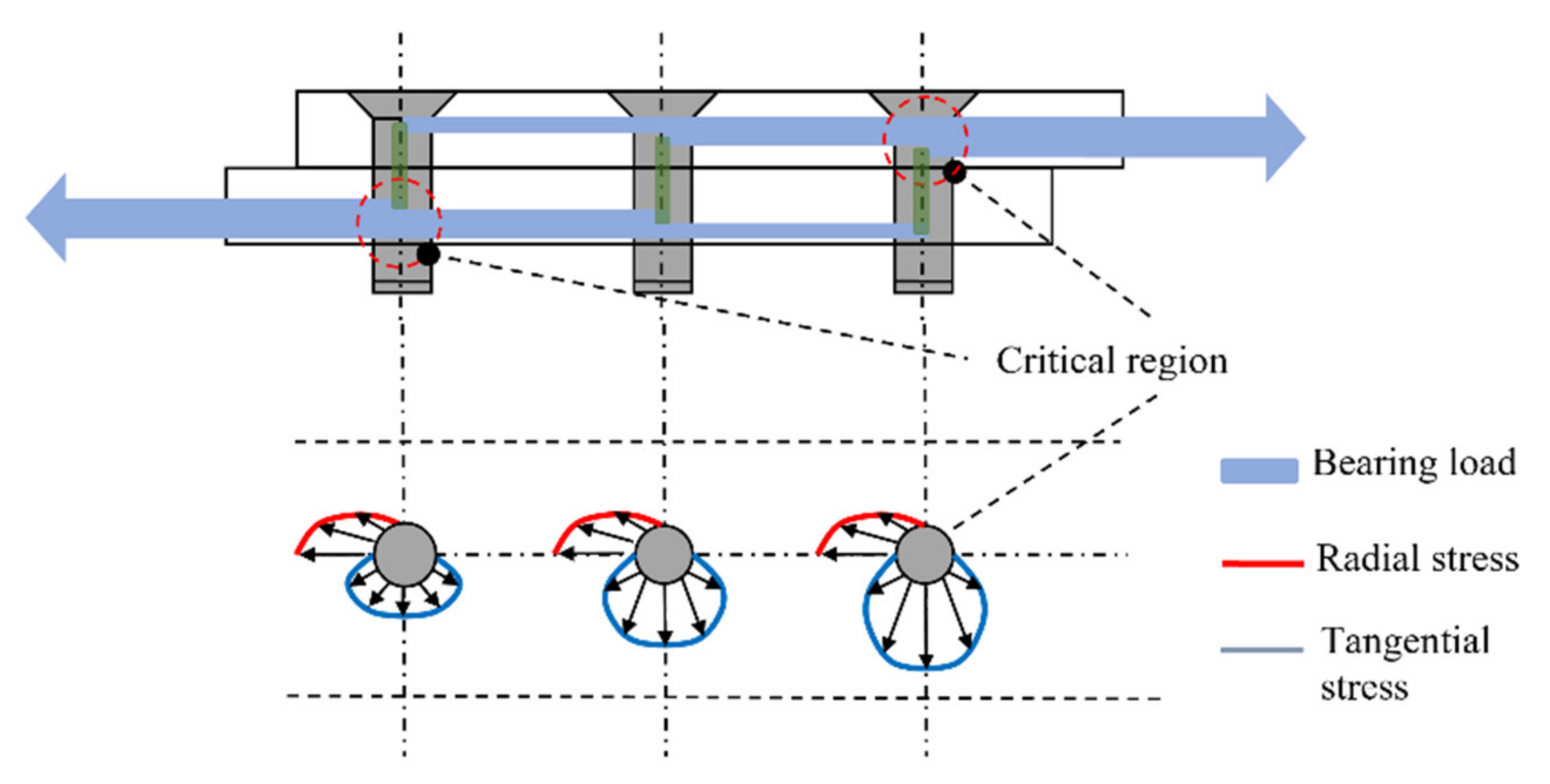
The way the loads are transmitted in single lap shear joint is presented in
Figure 1, (the case of a joint with three bolts). The bolt is in contact with the hole of the plate, therefore a percentage of the load is transmitted from the bolt to the other plate (bearing load), while the remaining load bypasses the bolt (bypass load). The contact of the bolt with the plate always results in the development of stresses in the radial direction (
Figure 1). Simultaneously, the bypass load results in the development of tangential stress around the hole. The tangential stresses around the hole are higher near the edges of the joint.
The bearing to bypass ratio depends on the characteristics of the joint and it remains constant up to failure. There are various types of microscopic failure of a bolted joint. The most common types are tension failure, shear out failure, and bearing failure. In addition, combined failure modes can also occur due to tension and shear (cleavage tension failure). The strength and the type of failure of a bolted joint, depends on a variety of factors, which are among other the boundary conditions, the loading type, the geometric characteristics of the joint (such as width, thickness of the plates, hole spacing and diameter), lamination properties (orientation and mechanical properties of the lamina), material, and geometric characteristics of the bolt [
21].
3. Assumptions for the Bolted Joint Analysis
In general, bolted joints are an important aspect of the structural integrity of an aerostructure (e.g., aircraft wing), hence their analyses are crucial for the sizing of the entire structure. The detail sizing of every joint requires the development of parametric models for simulating the bolts and the geometry of the laminated plates in detail. To build such FE models, 3D elements along with contact elements are required. The use of these detail models is not practical for the preliminary design phase of an aerostructure.
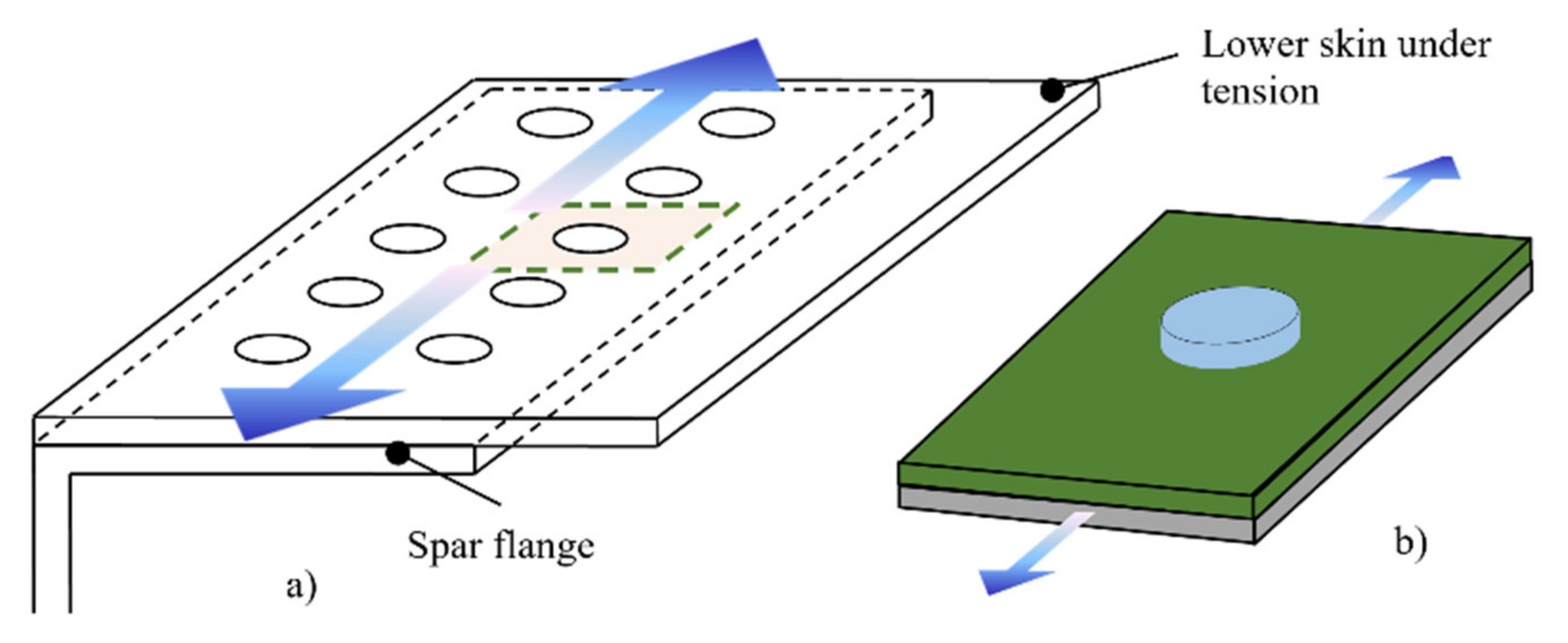
Consequently, to simplify bolted joint analysis, it is assumed that all bolts receive the same load (bearing load), and every hole in the laminated plate is bypassed by the same load (bypass load). This simplification allows the analysis of a joint with multiple bolts to be treated as a filled-hole problem. For example, the analysis of a bolted joint between two structural members (e.g., skin and spar between two consecutive ribs) includes a double row of bolts (
Figure 2a), that can be analyzed as a joint with a single bolt (conceptual model) (
Figure 2b). Despite the fact that the uniform loading introduces an error to the analysis, the obtained results are acceptable for the preliminary design phase.
4. Strength Calculations of a Single Lap Joint of Composite Plates
The main steps of the PDM are (a) the development of the FE model, (b) stress analysis, (c) the determination of the failure of the composite that is carried out with the use of failure criteria, (d) the degradation of the material properties of the material with the use of certain degradation rules, and (e) the final failure criterion. Steps b, c, and d of the methodology are part of an iterative loop that is executed up to the fulfilment of the final failure criterion (
Figure 3).
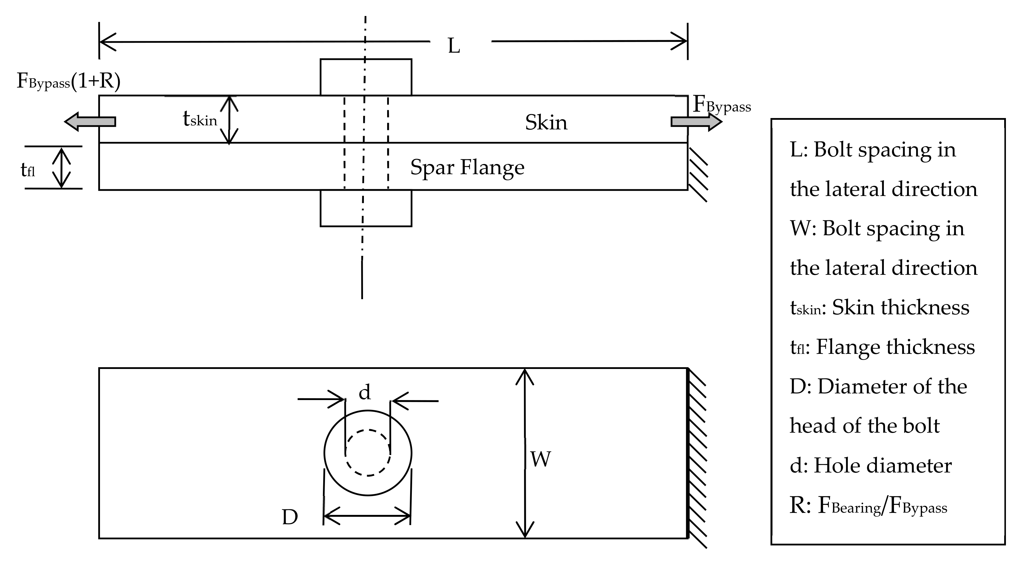
The investigated joints refer to laminated plates, which are connected with a titanium bolt with protruding head. In
Figure 4, the main dimensions of the joint and the loading are demonstrated. The laminated plate is loaded under tension or compression with (
, where R is the ratio of the bearing to bypass load. Regarding the boundary conditions, the one end of one plate is assumed to be clamped. The bolted joint with the forementioned loading and boundary conditions is analyzed up to final failure.
4.1. Stress Analysis with Finite Elements
The stress analysis of the bolted joint is carried out using FEM. Consequently, when a different joint configuration is investigated, it is required to develop a new numerical model. To this end, a three dimensional (3D) parametric numerical model, using the ANSYS Parametric Design Language (APDL) is developed. The purpose of having a 3D model is to consider interlaminar normal and shear stresses that develop through the thickness of the layered plate and result to delamination, which is one of the most important failure mechanisms of composites.
The element type used for the mesh of the FE model is SOLID185, taken from the element library of the ANSYS software [
22]. This element type has three (3) degrees of freedom per node, and it has layered capabilities, allowing to input the thickness and orientation of the lamination as parameters. Employing the layered element SOLID185 all stresses can be calculated (
σxx, σyy, σzz, σxy, σyz, σxz) and stored for every layer of the composite, expressed in the local coordinate system of the layer.
4.2. Failure Analysis of Composite Materials
A composite material can fail by different types of failure mechanics. As a result, multiple failure criteria exist for predicting and capturing all the different failures of composites [
23] (D.H. Allen et al.). The selection of the employed failure criteria is made considering the accuracy of the failure prediction that they offer. As a result, a set of Hashin-type failure criteria is selected to predict the matrix, fiber, shear tension, and compression, [
24]. Furthermore, to predict delamination, the criteria proposed by L. Ye [
25] are adopted in the present study. In
Table 1, all the applied failure criteria with their formulations are presented.
In the set of Equations (1)–(7) the nominators of the fractions are the stress resultants, in the referred direction, with respect to the layer’s local coordinate system. These values are calculated from the analysis of the FEM, while the denominators of the forementioned fractions are the nominal strengths [
26] of each layer.
In general, Hashin-type failure criteria are widely used in most of the PDM simulations, because they provide satisfactory failure predictions for various types of matrices (e.g., boron epoxy, glass-epoxy, etc.) [
25], as well as carbon fiber reinforced plastics (CFRPs), even with loaded holes (S.C. Tan [
27]). The failure criterion proposed by L. Ye is based on the work of Hashin–Rotem [
28] and it has been successfully used in previous works (e.g., P.P. Camanho [
29], F.K. Chang [
30], and T. Ireman [
31]) for predicting delamination of layered plates without stress concentration.
4.3. Degradation of the Composite Material Properties
When the failure criteria are applied, a failure may be detected in a particular location/layer of the composite material. Consequently, the material properties and hence the stiffness of this layer are degraded. This degradation is performed with the use of certain degradation rules that aim to reduce the ability of a layer to withstand specific types of loads. It must be highlighted, in this point, that since the effect of each failure type is different in the overall behavior of the composite material, the degradation rules are given as a function of the failure type.
According to the literature review two (2) sets of degradation rules are mostly used for PDM analyses: the rules proposed by F.K. Chang et al. [
30] and S.C. Tan [
27]. In the present contribution, the employed degradation rules are those proposed by F.K. Chang et al., as they are extended for three dimensions by Shokrieh and Lessard. The degradation rules, for each type of failure, are described below.
4.3.1. Degradation of Mechanical Properties Due to Matrix Failure under Axial Loads
This type of failure, when it is detected in a layer, is not catastrophic. It is assumed that the matrix is not capable of withstanding any loads, hence its stiffness in the direction of the matrix (
Ey) is degraded. The rest of the material properties do not change; thus the stiffness matrix of the layer is:
4.3.2. Degradation of Mechanical Properties Due to Fiber Failure under Axial Loads
This type of failure is catastrophic because when it is detected the layer cannot withstand any type of load. Consequently, the entire stiffness matrix of the layer is degraded as follows:
4.3.3. Degradation of Mechanical Properties Due to Shear between Matrix and Fiber
When this type of failure is detected in a layer, the material cannot withstand any in plane shear loads, but it can withstand loads in the direction of the matrix and the fibers, as well as in their transverse direction. As a result, the degraded stiffness matrix can be presented by the following equation.
4.3.4. Degradation of Mechanical Properties Due to Delamination under Axial Loads
This type of failure is not catastrophic when it is detected because the loads cannot be transmitted in the vertical direction of the layer. To apply this restriction, the Young’s modulus in the z-direction (vertical) is degraded as follows.
It is worth mentioning that when the mechanical properties of a layer are degraded, the values of the new properties are not changed to zero, instead they have a very small value. Further pieces of information regarding this matter are documented in [
26]. This is inevitable, since zero values for the mechanical properties of the FEM leads to convergence issues in the solution stage. The degradation rules affect the Poisson ratios as well, and they are performed by considering the compatibility ratios that applied from the constraints of the mechanical properties [
32].
4.4. Final Failure Criterion
The three stages of the developed methodology (stress analysis, failure prediction, and mechanical properties degradation) are implemented in an iterative algorithm, that its repetition terminates when a predetermined final failure criterion is satisfied. The physical meaning of this criterion is the loss of the bolted joint functionality.
The numerical results that yield from the PDM analysis include (a) the prediction and propagation of different failure types in every layer as a function of the load, (b) the change of stiffness of the joint through the load-displacement curve, and (c) the prediction of the remaining strength of the bolted joint.
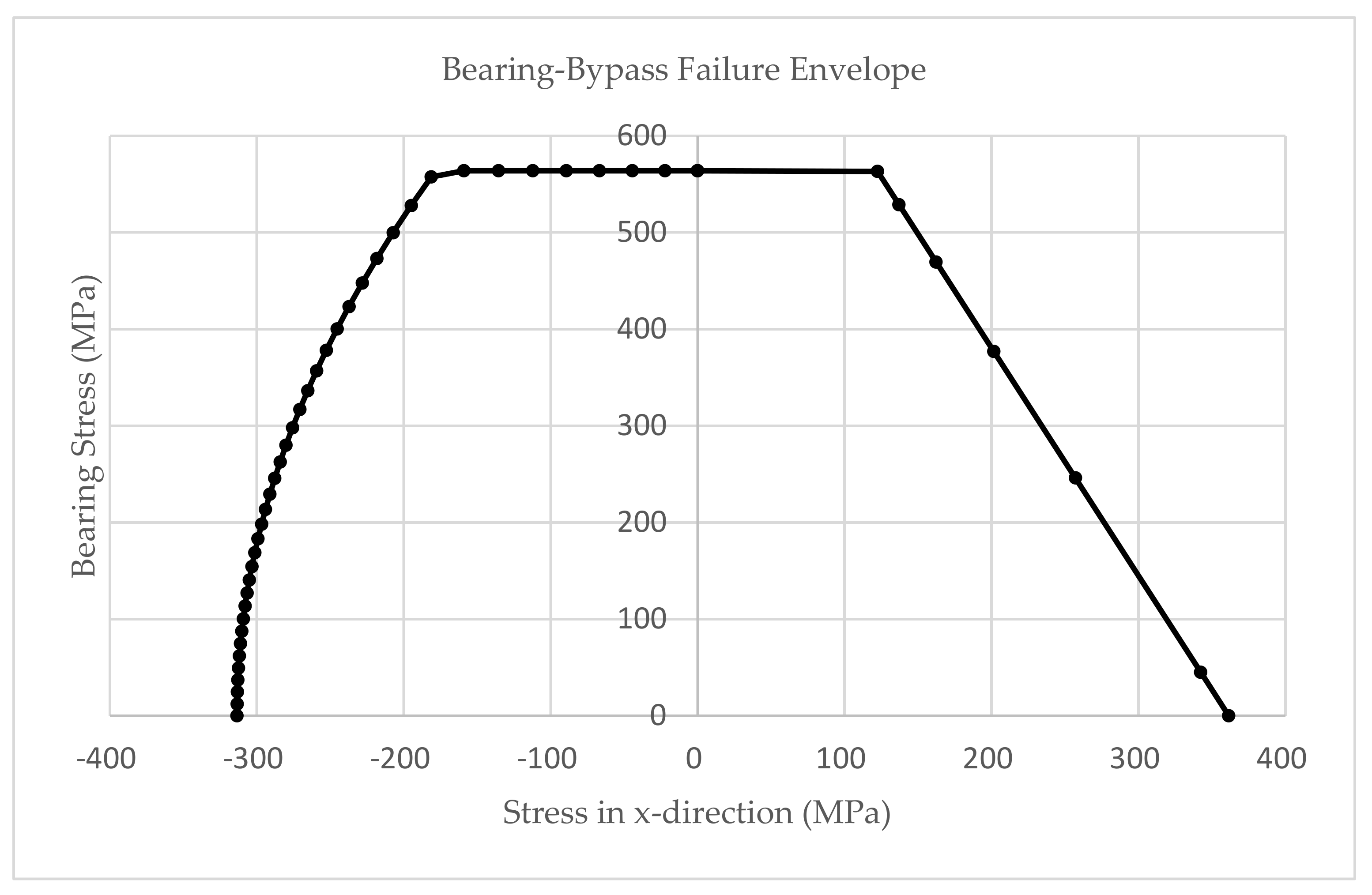
The parametric numerical model of the bolted joint is analyzed for different sets of geometric characteristics. In detail, the geometric parameters that varied are the hole diameter, thickness of the plate, and lamination. Additionally, each numerical FE model is analyzed under different loading conditions (tension and compression). Specifically, the analyses are carried out for different loading ratios (R), where R is the ratio of bearing load to bypass load. The predicted final failure determines the exact bearing and bypass loads when the bolted joint fails. By recording bearing and bypass loads at the failure of the joint, a failure envelope of the investigated joint is plotted (dotted line),
Figure 5 [
33].
The failure envelope is constructed based on numerical results only. A comparison between numerical and experimental results is also made, for specific cases, and a satisfactory agreement is achieved for a design criterion of the preliminary design phase. The validation, of this approach, is made with the respective experimental results that Airbus-UK owns.
5. Determination of Bolt Diameter, Bolt Spacing and Plate Thickness
The developed methodology is used to determine the bolt diameter, bolt spacing, and plate thickness for a skin-spar joint of a wing structure [
33,
34]. A typical bolted joint configuration with double series of bolts is assumed for this connection (
Figure 6). To calculate the required bolt diameter, it is assumed that the bolts between two consecutive ribs have the same diameter. According to the guidelines that Airbus-UK proposes and for avoiding any unreasonable failures, it has been assumed that the bolt spacing is four (4) times their diameter,
Figure 6.
The loads that are applied to the bolts and the plates, of every joint, are calculated according to Equations (12) and (13).
where
q is the shear flow from the spar webs while the
Flange Axial Load is the forces that are applied to the spar flanges. Equation (12) is used for calculating the bearing load, while for calculating the bolt diameter (
d) Equation (14) is employed by solving it with respect to
d.
Titanium bolts are selected for this application due to the high strength in shear that they possess, i.e., 662 MPa. To check the strength of the laminated plate of a bolted joint the failure envelope of
Figure 6 is utilized. According to the calculated loads, from Equations (12) and (13), the bolted joint is checked if it is in the ‘safe’ region. In case its configuration gives a point with coordinates outside the boundaries of the failure envelope, then it must be resized. Furthermore, the validation of the joint is concluded by checking that the bolt is bearing to the laminated plate. The validation is carried out using Equation (15). The respective bearing strength of laminate depends on the material used. An indicative value is 564 MPa.
where
tskin is the thickness of the spar flange and
d is the diameter of the hole.
6. Conclusions
In the current contribution a methodology is developed and presented for calculating the strength of a single lap joint. The methodology is based on the solution of a parametric numerical model of a bolted joint under different bearing to bypass ratios up to failure. The failure of the bolted joint is identified through the employment of PDM using suitable failure criteria and degradation rules under an iterative analysis. Through this process a failure envelope is constructed for a particular set of geometric and material characteristics of the bolted joint. Consequently, when a bolted joint must be checked for its functionality/structural integrity the applied loads are plotted to the failure envelope as a point with coordinates defined by the values of the bearing and bypass load. If the coordinates of the point fall within the respective failure envelope, then the bolted joint does not fail, and it can withstand the exerted loads. By repeating the forementioned process for a variety of bolted joint configurations (geometry and material properties), a set of failure envelopes can be constructed. Ultimately, the failure envelopes can be utilized, as a design criterion, for verifying or sizing the bolting of a structure. In this manner, the sizing of a bolted joint can be carried out solely by these failure envelopes, allowing an easy sizing process that can be automated via programming. The main advantage of this methodology is that the bolted joints can be sized in a prior design phase, such as preliminary design, instead on the detail design as they are traditionally considered. Therefore, no excessive computation cost and time is spent, since instead of running complicated FE models, Excel charts are used. Finally, by adopting these Excel charts, iterative calculations can also be performed for bolting sizing.


