1. Introduction
The results of studies on improving the performance of computing systems show that within the limits of positional number systems, a significant improvement cannot be expected without a considerable increase in the operating frequencies of elements and complications of the hardware of digital computing structures [
1]. An important issue is to choose an effective method for encoding numerical information, i.e., selecting a number representation for fast processing. The residue number system (RNS) is used to improve the efficiency of data encryption algorithms [
2,
3,
4], cloud computing [
5,
6,
7], digital signal processing [
8,
9], wireless networks [
10], matrix computing [
11,
12], and artificial neural networks [
13,
14]. One of the computationally complex operations in RNS is the Euclidean division or remainder division. Reducing the computational complexity of the remainder division algorithm will expand the range of RNS applicability for more efficient use of it in the implementation of numerical methods, etc.
Positional number systems, in which information is presented and processed in modern computing devices, have drawbacks. The main one for the speed limit is the presence of inter-digit transfers. They impose restrictions on the methods of implementing arithmetic operations. Therefore, it seems natural to construct an arithmetic system with no inter-bit transfers, i.e., a non-weighted number system. One of such systems is the RNS, where numbers are represented by the remainders of division by the selected bases of the system, and operations can be performed in parallel on each digit independently.
The development of computing devices based on the RNS began in the 1950s to 1960s of the 20th century. They were implemented in the form of modular coprocessors [
15].
If a series of positive integers
,
,
,
, called moduli or bases of the system, is given, then the RNS is a system in which a positive integer is represented as a set of remainders obtained by division by the chosen base
, where
for
[
1].
It is known from number theory that if the moduli are coprime, then the representation of the number is unique, and satisfies the condition , where is a dynamic range of number representation.
For numbers
and
the following expression holds:
where
.
However, despite several advantages, the RNS has the following disadvantages: limited action of this system by the field of positive integers, difficulty in determining the ratios of numbers in magnitude, determining if the result of an operation is out of range, etc.
Operations in the RNS can be divided into two groups: modular, where calculations are performed for each digit independently, and non-modular, which require, to one degree or another, knowledge of the positional characteristics of the number.
In
Section 2, we consider the features of division in the RNS, an approximate method based on the Chinese remainder theorem, the Akushsky core function, and also a block diagram of the division algorithm is presented.
Section 3 considers examples of the division operation implementation in the RNS in the form of a computing system.
Section 4 presents the main results of the work and directions for further research.
2. Features of Division in the Residue Number System
The division is one of the primary arithmetic operations. However, in RNS, the implementation of the modular division is computationally complex. There are methods for performing division with numbers of a specific type, for example, division with zero remainders, scaling, etc. [
16].
The well-known division algorithms in the RNS [
17,
18,
19] are based on comparing and subtracting numbers.
Let a dividend
, a divisor
, a quotient
, and a remainder
be given. Then
, while
. Consider the division algorithm based on the sequential approximation of the quotient
by degrees of the base of the number system, i.e., for a binary system, the process consists in finding
such that the equality holds
Substituting (1) into the division formula, we obtain
Thus, the division process can be reduced to a sequence of subtractions. Let
enter into the representation of the quotient
, that is,
, then we denote
, and
. Substitute
in (2).
Let us continue this process. We denote . Since is the sum of the remainder of the division and remaining members of the sequence of degrees of the number system are multiplied by the divisor, then is always satisfied.
If is not included in the representation of the quotient , i.e., , then . It is necessary to check the occurrence of for which is calculated.
In RNS, any number
is unambiguously represented by a set of residues
of dividing the number
by relatively prime moduli of the RNS
, where
,
is the working range of the RNS,
. The recovery of the number
from the RNS to the positional number system can be done, as in the prototype, using the approximate Chinese remainder theorem
where
,
,
is a multiplicative inverse. The application of the approximate method based on the Chinese remainder theorem is considered, in particular, in the patent [
20]. However, the
coefficient rarely turns out to be a finite fraction. Its rounding leads to accumulation errors.
The sign in the RNS is most often introduced by dividing the range into two parts, then, taking into account the dynamic range , in the RNS, it is possible to represent the numbers
, if is odd,
, if is even.
Then,
is positive if , if is even, , if is odd,
is negative if , if is even, , if is odd.
To perform division according to formula (2), it is necessary to compare RNS numbers and determine their signs.
Since the RNS is a non-weighted number system, then for comparing numbers and determining the sign, i.e., finding the position of the number on the number line, it is necessary to calculate the positional characteristic. An example of a positional characteristic is the Chinese remainder theorem with fractions used in the prototype. Another positional characteristic can be a core function, introduced by I. Ya. Akushsky [
21,
22]:
The numbers
, called weights, can be arbitrary. They define each specific core function and can vary depending on the task. The essential property of the core function is that its maximum range can vary and can be significantly less than the
number, depending on the choice of weights. For example, you can use as
some arbitrary value
, which has the properties necessary for solving a specific problem. The values of the core function
, specified by the weights
, under the condition
,
, can be calculated using the formula
where
are the orthogonal bases of RNS. However, in general, the core function does not have the monotonicity required for comparing numbers.
To construct a core function with specified properties, we use the following algorithm (Algorithm 1).
| Algorithm 1: Selection of parameters for the core function of a special type for a given set of moduli. |
Input: Set of RNS moduli . It is required to construct a core function with a module of a special type with and non-negative coefficients.
Output: Coefficients of the constructed core function.
Let . For the given value calculate , , and , where . Calculate Q by the formula . If , then and go to step 2. Otherwise, go to step 5. Choose such a that . Calculate for . Check the conditions for the absence of critical cores from below: and the absence of critical cores from above: , for all . If it does not hold, and go to step 2.
end. |
The core function with the given properties is given by expression (4), where
To compare numbers, let us use the following Algorithm 2.
| Algorithm 2: Comparison of numbers represented in the RNS using a core function with non-negative coefficients. |
Input: and
Output: , or end. |
In this case, non-negative coefficients are taken, and is the first non-zero coefficient.
To determine the sign of a number, it is necessary to construct a core function such that for positive numbers and for negative numbers, where if is even ( if is odd). is the middle of the RNS range. Therefore, use Algorithm 2 for and .
Let us consider an example of division in RNS based on function (4) and Algorithm 2.
We take as RNS. Then , , , , , , , , , , , . Using Algorithm 1, we obtain , .
Then, the auxiliary values are equal to .
The core function takes the form
The middle of the RNS range is , for which .
We find the quotient of dividing by Let us check the signs of the dividend and the divisor, for which we calculate and :
, the number is negative,
, the number is positive.
Since the dividend and divisor are different signs, the result will be negative. For the dividend, we find the opposite value, to perform division over the absolute values. For this, in the RNS, it is necessary to subtract the corresponding remainder from the modulus.
We get
. Representations of powers “2” in RNS can be calculated in advance, depending on the range of RNS (the highest occurrence power of
is
) and stored in memory:
The highest possible degree of quotient when performing division is equal to the dimension of the dividend. It is necessary to multiply the divisor sequentially by
to find the number for which the values of the core function satisfy the expression
.
Using the formula (2), we calculate
:
It means that
is not included in the representation of the quotient
. Let us check
by calculating
:
It means that
is included in the representation of the quotient
. Let us check
, by calculating
:
It means that
is included in the representation of the quotient
. Let us check
, by calculating
:
It means that
is included in the representation of the quotient
. Let us check
by calculating
:
It means that
is included in the representation of the quotient
. Let us check
by calculating
:
It means that
is included in the representation of the quotient
. Let us check
by calculating
:
It means that
is included in the representation of the quotient
. Let us check
by calculating
:
It means that is included in the representation of the quotient .
Since the result must be negative, then
. Let us check:
3. Implementation of the RNS Division
Let us consider the block diagram of the division of numbers represented in the RNS (
Figure 1) [
23].
Figure 1 shows the general block diagram of the division calculation, which contains the input of the dividend
, input of the divisor
, block for calculating positional characteristics, block for refining the approximation series, block for the derivation of the quotient, and output of the quotient
. The inputs of the dividend
and the divisor
are connected to the first and second input blocks for calculating positional characteristics.
From the first output of the block for calculating positional characteristics, the sign value of the result is fed to the first input of the quotient output block.
From the second output of the block for calculating positional characteristics, the signal “” is sent to the second input of the quotient output block, i.e., the result of the division is 0.
From the third output of the block for calculating positional characteristics, the signal “” is sent to the third input of the quotient output block, i.e., the division result is , depending on the signs of the input numbers.
From the fourth and sixth outputs of the block for calculating positional characteristics, the absolute values of the dividend and divisor are sent.
From the fifth output of the block for calculating positional characteristics, the value of the core function of the absolute value of the dividend is sent to the second input of the block for refining the approximation series.
The signal of the end of enumeration of powers “2” included in the representation of the quotient is received from the first output of the block for refining the approximation series to the fourth input of the quotient output unit.
The first output of the quotient output block is the quotient output.
Figure 2 shows a block diagram for calculating positional characteristics, which contains inverters of the dividend and divider, blocks for multiplying by constants and for addition, blocks for determining the sign, dividend and divisor multiplexers, an XOR element, and a comparison block.
At the inputs of the dividend and the divisor, the values of the dividend and the divisor are sent, represented in RNS as and .
In inverters of the dividend and divisor, the opposite values and are calculated, correspondingly.
In the RNS, to obtain the opposite value , it is necessary to subtract the corresponding remainder from the modulus . Then, the numbers and , and in the blocks of multiplication by constants are multiplied by the constants of the values of the core function of the RNS orthogonal bases , i.e., in each block, there is a parallel multiplication of the residues by according to the formula (4).
The values of the products from the multiplication blocks by the constants are fed to the inputs of the addition blocks, the output of which is the lowest bits of the sum, which corresponds to finding the remainder modulo in formula (4). is determined in advance by Algorithm 1 while constructing the core function.
The values of the dividend and the divisor from the inputs of the dividend and the divisor, respectively, are sent to the first inputs of the sign determination blocks. The values of the core function and from the outputs of the addition blocks are sent to the second inputs of the sign determination blocks. In the blocks for determining the sign, the values of the core function and the remainders are compared on one of the bases with the middle of the RNS range according to Algorithm 2.
The signs of and from the outputs of the blocks for determining the sign are sent to the inputs of the XOR element, as well as to the control inputs of the corresponding multiplexers. The XOR element output is the first output of the positional characteristic calculation block.
The first and second inputs of the multiplexer of the dividend receive the value of the core function from the output of the addition block and the value of the dividend from the input of the dividend.
The third and fourth information inputs of the multiplexer receive the value of the core function from the output of the addition block and the value from the output of the inverter.
The first output of the multiplexer is connected to the second input of the comparison unit and the fifth output of the positional characteristics calculating unit and transfers the value of the core function from the absolute value of the dividend . The second output of the multiplexer is connected to the first input of the comparison unit and is the fourth output of the unit for calculating positional characteristics. It transmits the absolute value of the dividend .
The first and second inputs of the divider multiplexer receive the value of the core function from the output of the addition block, and the value of the divider from the input of the divider. The third and fourth information inputs of the multiplexer receive the value of the core function from the output of the addition block, and the value from the output of the inverter. The first output of the multiplexer is connected to the third input of the comparison unit. It transfers the value of the core function from the absolute value of the divisor . The second output of the multiplexer is connected to the fourth input of the comparison unit, is the sixth output of the positional characteristics calculating unit and transmits the absolute value of the divider .
The comparison block is based on Algorithm 2. It compares the absolute values of the dividend and divisor with and values, respectively. It sends to the first output of the comparison unit a signal in the case of “”, which is fed to the second output of the positional characteristics calculating unit. It sends a signal to the second output of the comparison unit in the case of “”, which is fed to the third output of the block for calculating positional characteristics.
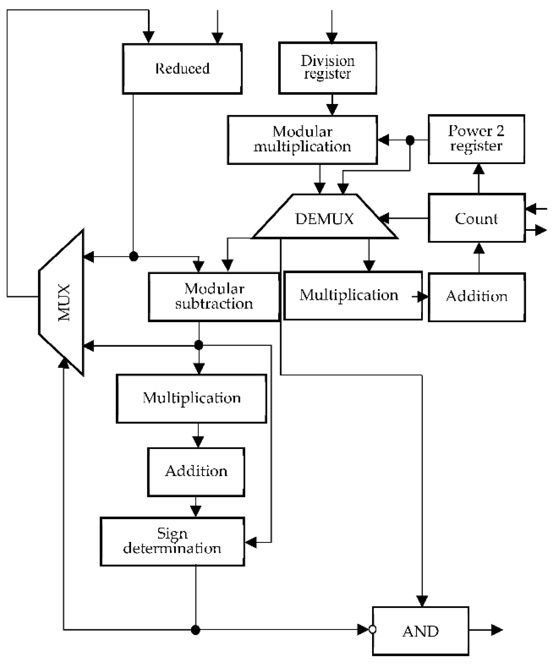
Figure 3 shows the block for refining the approximation series. It contains the storage register of the reduced, storage register of the divisor, modulo multiplying register, storage register of degrees “2”, power counting unit, demultiplexer, multiplexer, modulo subtraction block, multiplication by the constants blocks, addition blocks, block for determining the sign, and logical element AND.
The value from the first input of the refinement block of the approximation series is received at the first input of the storage register of the reduced one. The input of the divider storage register is the third input of the approximation series refinement block. It transmits the value to the first input of the modulo multiplication unit, where the divider is multiplied by the power of “2”, presented in the RNS, which come from the first output of the storage register of the powers of “2”.
Additionally, degrees “2” from the first output of the storage register are fed to the second input of the demultiplexer. The first input receives the value of the product from the output of the multiplying unit.
The degree counting unit determines the degree “2”, for which the product and then it counts down the degrees to check the occurrence of the power “2” in the representation of the quotient . To determine the maximum degree “2”, the power count unit supplies the first output connected to the first input of the power storage register “2” with the address values starting from 1, while the maximum degree is equal to , the storage register of degrees “2” supplies the first output of degrees “2” presented in the RNS.
The second output, connected to the control input of the demultiplexer, is supplied with the value of the operating mode: direct or countdown degrees.
In the direct counting case, the value of the product from the output of the modulo multiplication unit is fed to the third output of the demultiplexer. It is connected to the input of the multiplication unit by a constant where the values of the core function from the orthogonal bases of the RNS are multiplied and then added in the addition block.
The least significant bits of the result are fed to the second input of the power counting block, where it is compared with the value of the dividend core function, which is fed to the first input of the power counting block from the second input of the approximation series refinement block.
In the countdown case, the value of the product from the output of the modulo multiplying unit is fed to the first output of the demultiplexer, to the second output of which the value of the power “2” is supplied. At the end of the countdown, a signal about the end of counting is sent to the third output of the power counting unit.
In the subtraction unit, subtraction is performed according to formula (2). The first input is fed from the output of the storage register of the reduced product, and the second one is fed from the first output of the demultiplexer.
The result of subtraction is fed to the input of the multiplying unit by constants, from where it is fed through the addition unit to the first input of the sign determination unit, the second input of which is connected to the output of the modulo subtraction unit, which is also connected to the second information input of the multiplexer.
The output of the sign determination unit is connected through the inverter to the first output of the AND logic element, the second input of which receives degrees “2” from the second output of the demultiplexer, and to the control input of the multiplexer, the first input of which is connected to the output of the storage register of the decreasing one, and the output of the multiplexer is connected to the second to the input of the storage register of the decrement. The output of the AND gate is the second output of the approximation series refinement block.
Figure 4 shows a quotient output block containing a modulo addition block, demultiplexer, inverter, storage register “1” in the RNS, storage register “−1” in the RNS, private multiplexer, unit multiplexer, quotient selection multiplexer, and the AND logic gate.
Degrees “2” from the fifth input of the quotient output unit are fed to the first input of the modulo addition unit. Its output is connected to the output of the demultiplexer.
Depending on the end-of-count signal, it connects to the demultiplexer control input from the fourth input of the quotient output unit, feeds the result to the second input of the block addition modulo or to the second input of the quotient multiplexer and to the first input of the quotient multiplexer through the inverter.
The signal of sign from the first input of the quotient output unit is fed to the control inputs of the quotient multiplexer and unit multiplexer. Its first and second information inputs receive signals from the outputs of the storage register “1” in the RNS and the storage register “−1” in the RNS, respectively.
The outputs of the quotient multiplexer and unit multiplexer are connected to the first and second inputs of the private selection multiplexer. Its control input receives the signal “” from the third input of the private output block. The output of the private selection multiplexer is connected to the first input of the AND gate. The signal “” is supplied through the inverter from the second input of the private output. The output of the AND gate is the output of the quotient .
4. Discussion
This section presents a description of the example for verification of obtained results, their interpretation, as well as the conclusions that can be drawn.
Let us consider an example for the RNS
. According to Algorithm 1, the internal parameters
,
,
,
, and
are calculated. The constant multiplication blocks multiply each of the four remainders of the number by
,
,
, and
, respectively. Addition blocks add the obtained products and output the least significant
bits of the number. Thus, pairs of blocks of multiplication by constants with addition blocks implement the formula
The inverters find the opposite value for the number represented in the RNS by subtracting the corresponding remainder from the modulus.
is fed to the input of the dividend, which, after calculating the core function by blocks of multiplication by constants and addition, feeds the value to the second input of the sign determination block, to the first input of which is sent from the input of the dividend.
In the block for determining the sign, a comparison is made with and according to Algorithm 2. The value of the sign of is 1 (negative) and it is fed to the control input of the dividend multiplexer, and to the first input of the XOR element. Additionally, the value is fed to the inverter, the result of which is .
After calculating the core function by the constant multiplication and addition blocks, is obtained. is fed to the first information input of the multiplexer. is fed to the second information input. is fed to the third information input. is fed to the fourth information input. Since the dividend is negative, is fed to the first output of the multiplexer of the dividend and is fed to the second output.
At the same time, is fed to the input of the divider, which, after calculating the core function by the blocks of multiplication by constants and addition, feeds the value to the second input of the sign determining block, the first input of which is from the input of the divider. In the block for determining the sign, a comparison is made with and according to Algorithm 2.
The value of the sign of is 0 (positive), and it is fed to the control input of the divider multiplexer and to the second input of the XOR element. In addition, the value is fed to the inverter. The result is . After calculating the core function by the constant multiplication and addition blocks, is obtained. is fed to the first information input of the multiplexer, is fed to the second information input, is fed to the third information input, and is fed to the fourth information input. Since the divisor is positive, is fed to the first output of the multiplexer, and is sent to the second output.
Since the signs of the dividend and the divisor are different, signal 1 is sent to the output of the XOR element, i.e., the result is negative. The comparison block is based on Algorithm 2. and are compared with and coming from the dividend and divisor multiplexers. Since , then , “”, and “”, 0 is sent.
Thus, the sign of result 1 is fed to the first output of the block for calculating positional characteristics. The zeros are fed to the second and third outputs, which means that the conditions “” and “” are not met. At the fourth, fifth, and sixth outputs, respectively, there are the values , and .
is fed to the input of the divider storage register. The degree counting unit delivers to the first output the address of the power “” represented in the RNS, which is stored in the degree storage register “2”.
The value (2,2,2,2) is fed to the second input of the modulo multiplication block, the first input of which is (1,10,6,4). The result (2,7,12,8), under the action of the signal at the control input of the demultiplexer, is fed to the multiplication and addition blocks. The value of the core function is calculated. In the degree counting unit, this value is compared with , which is fed to the first input. Since , the degree counting continues. This countdown continues until , for which . After that, the degree counting unit goes into the countdown state and sends a corresponding signal to the control input of the demultiplexer.
The degree counting unit delivers to the first output the address of the power “” represented in the RNS, which is stored in the degree storage register “2”. The value (7,11,9,14) is fed to the second input of the modulo block, the first input of which is (1,10,6,4).
The result (7,6,3,18), under the action of a signal at the control input of the demultiplexer, is fed to the second input of the subtractor modulo, to the first input of which is fed.
The result is fed to the blocks of multiplication by a constant and addition, in which the value of the core function is calculated. It is fed to the first input of the block for determining the sign, to the second input of which the value is sent, since the number , then and is not included in the representation of the quotient .
“1” is sent to the output of the block for determining the sign, which arrives to the multiplexer control input, overwriting the value in the decrement storage register. Additionally, 1 from the output of the sign determination unit is fed to the inverted first input of the AND gate, zeroing the value of the power “” supplied from the second output of the demultiplexer.
Further, the degree counting unit feeds to the first output the address of the degree “”, represented in the RNS, which is stored in the degree storage register “2”. The value (9,12,13,7) is fed to the second input of the modulo block, the first input of which is (1,10,6,4). The result (9,3,10,9), under the action of a signal at the control input of the demultiplexer, is fed to the second input of the subtractor modulo, to the first input of which is fed. The result is fed to the blocks of multiplication by a constant and addition, in which the value of the core function is calculated, which is fed to the first input of the block for determining the sign, to the second input of which comes the value of , since the number , then and is included in the representation of the quotient .
At the output of the block for determining the sign, 0 is sent, which is fed to the control input of the multiplexer, recording the value of in the storage register to be reduced. In addition, 0 from the output of the sign determining block is fed to the inverted first input of the AND gate, passing the value of the power “” supplied from the second output of the demultiplexer to the second output of the approximation series refinement block.
The rest of the degrees are checked in the same way. Finally, the degree counting unit sends to the first output the address of the “” represented in the RNS, which is stored in the degree storage register “2”. The value (1,1,1,1) is fed to the second input of the modulo block, the first input of which is (1,10,6,4). The result (1,10,6,4) under the action of the signal at the control input of the demultiplexer is fed to the second input of the subtractor modulo. The first input is sent with from the output storage register decreasing.
The result is fed to the blocks of multiplication by a constant and addition, where the value of the core function is calculated, which is fed to the first input of the block for determining the sign. The second input receives the value , since the number . Then and are included in the representation of the quotient .
“0” is sent to the output of the block for determining the sign, which is fed to control input of the multiplexer, writing the value of in the storage register to be reduced. In addition, “0” from the output of the sign determining block is fed to the inverted first input of the AND element, passing the value of the power “” supplied from the second output of the demultiplexer to the second output of the approximation series refinement block. The end of the counting signal is sent to the third output of the power counting block.
The final quotient is formed in the block of the output of the quotient. The first input of the modulus addition block sequentially receives the degrees “2” included in the representation of the quotient . The second input of the modulus addition block receives the sum of the previously obtained degrees.
The number “” after logical multiplication with zero is equal to (0,0,0,0), entering the first input, is added with (0,0,0,0). Then
is added with .
is added with ,
is added with ,
is added with ,
is added with ,
is added with ,
is added with
The result under the effect of the signal of the end of the counting of the fourth input of the quotient output block to the control input of the demultiplexer is fed to the input of the inverter, where the opposite value is located, arriving at the first input of the multiplexer quotient, the second input of which receives from the second output of the demultiplexer.
Since the control inputs of the private multiplexer and the unit multiplexer receive a signal that the result is negative, the value from the inverter and from the storage register “” in the RNS. Under the action of the signal “” (in this case 0) from the third input of the quotient output unit to the control input of the quotient selection multiplexer, the value is sent to the output from the inverter and since the signal “” (in this case, 0) from the second input of the quotient output block is inverted by the second input of the AND gate, then the quotient output is supplied with the value , which corresponds to the value .
5. Comparative Analysis
The proposed implementation of the Euclidean division algorithm reduces the size of the operands by half compared to the algorithm from [
17] by using the Akushsky core function instead of the approximate method. On the other hand, using the Akushsky core function without critical cores allows reducing the depth compared to the algorithms from [
18,
24,
25,
26] (see
Table 1). By depth, we mean a number of the RNS processor elements, circuit for arithmetic or Boolean operations, such as addition, multiplication, modulo, etc.
Akushsky core function is a generalization of the Pirlo and Impedovo function. Both Akushsky’s core function and approximate method possess similar arithmetic options and used for similar application areas, for instance, Euclidean division algorithms. However, Akushsky’s core function avoids computational errors arising due to rounding operations.
6. Conclusions
We propose an enhanced modular division implementation. It has an improved accuracy and performance with minimal hardware requirements. The proposed method reduces the size of the operands by half in comparison with the RNS division algorithm based on the approximate method. The field programmable gate arrays (FPGAs) implementation can be used both as a separate device and as a coprocessor to perform non-modular operations.
We use Akushsky core function with no critical cores due to its monotonicity, which allows accurately comparing numbers and determining the sign of the number.
Our method improves the accuracy of calculating the division of numbers and determining the sign of the RNS numbers by avoiding rounding errors arising when the approximate method based on the Chinese remainder theorem is used.


