Article

Development of a Computational Tool for the Estimation of Alveolar Bone Loss in Oral Radiographic Images

1
Department of Mechatronics, Manipal Institute of Technology, Manipal Academy of Higher Education, Manipal 576104, Karnataka, India
2
Department of Periodontology, Manipal College of Dental Science, Manipal, Manipal Academy of Higher Education, Manipal 576104, Karnataka, India
3
Department of Instrumentation & Control Engineering, Manipal Institute of Technology, Manipal Academy of Higher Education, Manipal 576104, Karnataka, India
4
Department of Biomedical Imaging, Universiti Malaya Research Imaging Centre, Faculty of Medicine, Universiti Malaya, Kuala Lumpur 50603, Malaysia
5
Department of Oral Medicine and Radiology, Manipal College of Dental Science, Manipal, Manipal Academy of Higher Education, Manipal 576104, Karnataka, India
6
Department of Medicine, Columbia University, New York, NY 10032, USA
7
School of Engineering, Ngee Ann Polytechnic, Singapore 599489, Singapore
8
Department of Biomedical Informatics and Medical Engineering, Asia University, Taichung 41354, Taiwan
9
Department of Biomedical Engineering, School of Science and Technology, SUSS University, Singapore 599494, Singapore
*
Author to whom correspondence should be addressed.
Computation 2022, 10(1), 8; https://doi.org/10.3390/computation10010008
Submission received: 24 November 2021 / Revised: 7 January 2022 / Accepted: 7 January 2022 / Published: 12 January 2022
(This article belongs to the Section Computational Engineering)

Abstract

:
The present study evaluated a newly developed computational tool (CT) to assess the alveolar bone space and the alveolar crest angle and compares it to dentist assessment (GT). The novel tool consisted of a set of processes initiated with image enhancement, points localization, and angle and area calculations. In total, we analyzed 148 sites in 39 radiographic images, and among these, 42 sites were selected and divided into two groups of non-periodontitis and periodontitis. The alveolar space area (ASA) and alveolar crest angle (ACA) were estimated. The agreement between the computer software and the ground truth was analyzed using the Bland–Altman plot. The sensitivity and specificity of the computer tool were measured using the ROC curve. The Bland–Altman plot showed an agreement between the ground truth and the computational tool in all of the parameters assessed. The ROC curve showed 100% sensitivity and 100% specificity for 12.67 mm of the alveolar space area. The maximum percentage of sensitivity and specificity were 80.95% for 13.63 degrees of the alveolar crest angle. Computer tool assessment provides accurate disease severity and treatment monitoring for evaluating the alveolar space area (ASA) and the alveolar crest angle (ACA).

1. Introduction

Periodontal disease is associated with the loss of alveolar bone. The loss rate can be slow and continuous, or episodic, and is manifested as a horizontal or angular type [1]. Loss of alveolar bone occurs as a consequence of pathogenic microorganisms, or the red-complex bacteria due to the host and the bacteria-induced inflammatory response [2]. It is manifested clinically by losing the surrounding soft tissue that anchors and attaches the teeth with the underlying alveolar bone. A diagnosis can be established via a clinical examination of the gingival tissues, and radiographically by checking the interdental bone loss. The alveolar bone loss is directly related to the survival of teeth in the oral cavity. Alveolar bone loss measurement in radiography is a difficult task. Studies have calculated the linear measurement of bone loss on the mesial and distal surfaces of the root using the bone defect angle. The bone defect angle was measured between the line on the alveolar crest and the line on the root surface [3].
The earlier method used for measuring the degree of bone loss was conducted via a Schei ruler [4,5]. The digital revolution could be traced with the development of the DIA tool in 2009 [3], automated CEJ localization and bone loss area assessment [4,6], Multimodal 3D imaging [7], development of a deep CNN algorithm in 2018 and 2019 [8,9], and the deep learning hybrid method [10]. The digital image analyzer (DIA) has added the periodontal intrabony defect angle as a new function to the old digital image analyzer. An essential aspect of reading a radiographic image is to identify key landmarks, such as the cementoenamel junction (CEJ) and the crest of the alveolar bone. The DIA method showed high sensitivity and specificity for detecting the cementoenamel junction and the crest of the alveolar bone. The degree of bone loss is measured vertically and is determined by the defect angle between the two lines representing the root surface of the side of the tooth and the surface of the bone defect. The critical points for either the horizontal or vertical measurement are the positions of CEJ (cementoenamel junction) and ALC (alveolar crest); they must be marked manually by a dentist or determined automatically by the software [11]. The localization of the CEJ can be performed both clinically and radiographically. The radiographic method uses the OPG (Orthopantomograph), IOPA (Intraoral Periapical), Bitewing, and RVG (Radiovisiography) [12]. In general, radiographic examination enables the accurate evaluation of crestal-bone architecture, crown-root ratios, vertical or horizontal bone defects, furcation involvement, and the overall morphology of the bone [6].
In another study, the degree of alveolar bone loss was assessed by the localization of ALC, CEJ, and the apex of the teeth, with the Schei ruler being used for plotting. This study employed software to extract the tooth contour and bone loss area from radiographic imagery prior to estimating the degree of alveolar bone loss [13]. This was comparable to the ground truth evaluated by a dentist. There have been methods for extracting the tooth contour and localization of the cementoenamel junction using template recognition to calculate the tooth area from the face image. The hybrid differential method and the membership function technique were adopted to match the identity of the teeth [14]. The seam carving method offers the lowest failure rate for segmentation [15]. Cartesian coordinates have been used to extract the 3D space between the teeth [16].
The estimation of bone defects due to periodontal disease has been researched widely, and the features have been commonly extracted using segmentation. The area measured was within the bone defect angle (BDA). The BDA was measured as shown in Figure 1a. However, the defect angle is vertical even if the teeth are tilted, and the angle increases when there is a bone fill or regrowth with the treatment. Hence, we wanted to localize the point at the CEJ (cementoenamel junction) (points A and B) (Figure 1b) between the adjacent teeth and the points at the crest of the alveolar bone (Points C and D) at the meeting point of the root. Therefore, the angle of bone loss or the alveolar crest angle was between AB and CD, as shown in Figure 1b. This angle would decrease with treatment for the defect and can be calculated using a computer tool. Further, it is necessary to know the alveolar space area (Figure 1b) of the interdental region of the alveolar bone space to determine the exact amount of the lost space.
The existing techniques to measure the alveolar bone loss are via a Schei ruler or similar digital software. These methods provide the amount of bone loss as a percentage value. However, an exact estimate using this value for comparison is not possible. Similarly, the existing technique to measure the bone defect angle is as depicted in Figure 1a. Nevertheless, this method cannot be utilized since it does not match the angle proposed in the new method. Hence, we needed to calculate the area and the angle of the defect manually and then compare with the computational tool. A protocol could be developed with good diagnostic and prognostic value. To the best of our knowledge, prior studies did not estimate the precise alveolar bone loss/gain and angle. Hence, the objectives of our work were as follows: To evaluate the area of the alveolar bone loss space in non-periodontitis and periodontitis patients using a manual method (ground truth); to evaluate the alveolar crest angle in non-periodontitis and periodontitis patients manually (ground truth); and to determine the agreement between the results as estimated by the dentist (used as ground truth) with that of the computational tool.
The study was designed with the hypothesis that there was no agreement in assessing the alveolar bone space and the alveolar crest angle between the computational tool and the dentist’s assessment.

2. Materials and Methods

2.1. Collection of Study Samples

The analysis of the alveolar space area that corresponded to the radiolucency coronal to the crest was carried out on 148 sites in 39 orthopantomogram radiographs (OPGs). All OPGs were obtained after prior permission and ethical clearance from the Institutional Ethical Committee (IEC No. 507/2019). The selection criteria for the OPGs included those obtained from adult patients with or without generalized periodontal disease. The selection of patients with periodontitis was clinical loss of attachment, probing depth greater than 4 mm, and/or gingival recession in more than 30% of the sites. Cases of radiographs with teeth having proximal restorations at the assessment site, the inability to locate cementoenamel junction, and missing adjacent teeth were excluded.
All orthopantomograms were exposed using the same unit Planmeca Promax with 68 KV, 16 mA, DAP (dose area product) of 87 mGycm2 2.5 mm of Aluminum equivalent total filtration, and they were acquired with the dimension 9 × 136 mm PAN CCD sensor. The resolution of the images was set to 12–16-bit gray levels.
The obtained radiographs were randomly divided into two groups: one group of patients with periodontal disease and the other group consisted of healthy subjects. Forty-two sites in total were selected to estimate the alveolar space area and the alveolar crest angle, with 21 sites in the no-periodontitis group and 21 sites in the periodontitis group.

2.2. Computational Tool

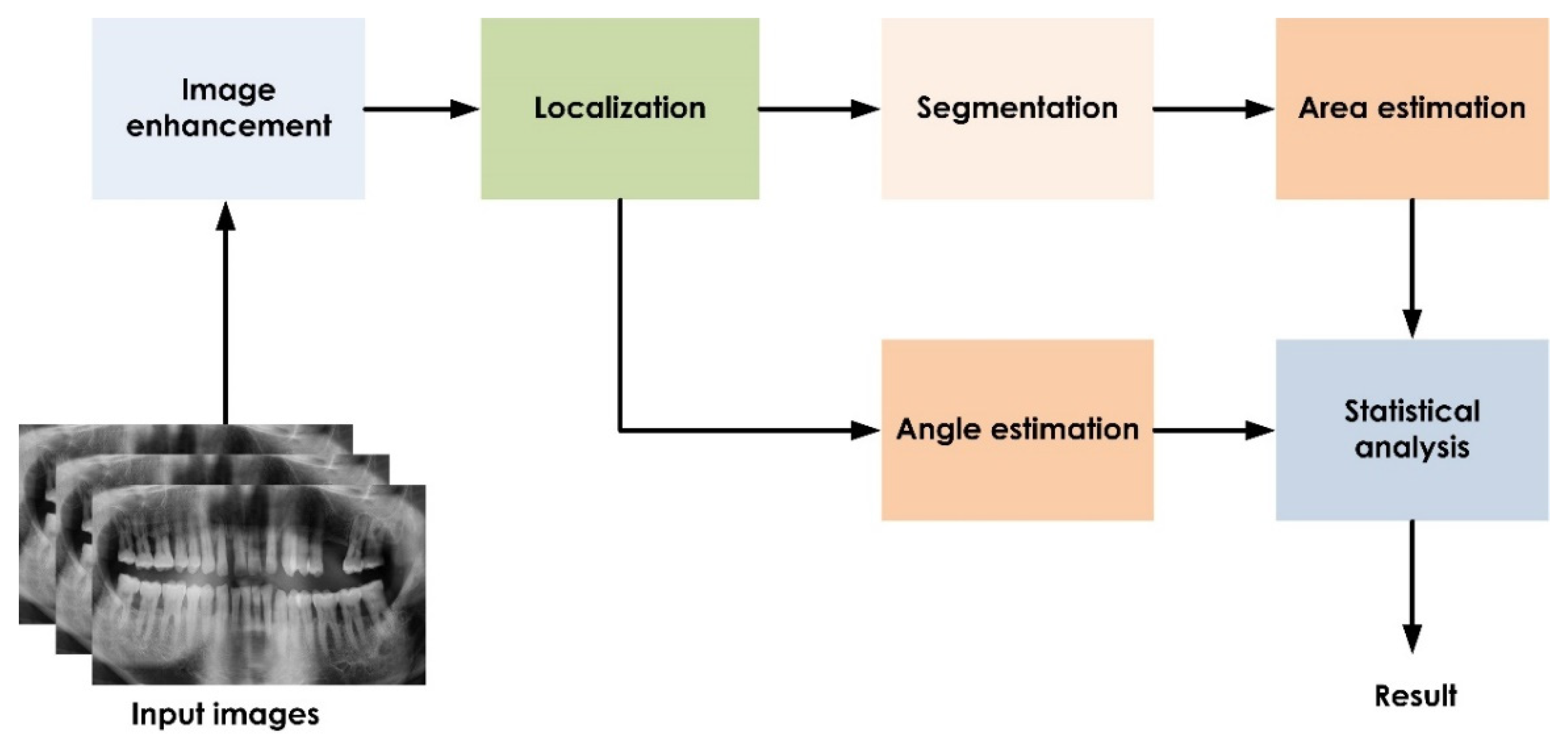
This method measured the area between the cementoenamel junction of two adjacent teeth and the alveolar crest line. Next, the loss angle was calculated between the cementoenamel junction of two teeth and the line at the alveolar crest, which we term the specific amber line (SAL) [17]. First, the method was initialized by applying the image enhancement technique, CLAHE, to improve radiographic quality. Next, the localization of the points (cementoenamel junctions and the alveolar crest points) was performed manually by two examiners (SK, SM) to obtain the coordinate points, which were then used to obtain bone loss angle. The localized images were then segmented using an active contour model. Finally, the area was calculated using the extracted region of interest. The primary processing blocks of the proposed system are shown in Figure 2.

2.3. Image Enhancement

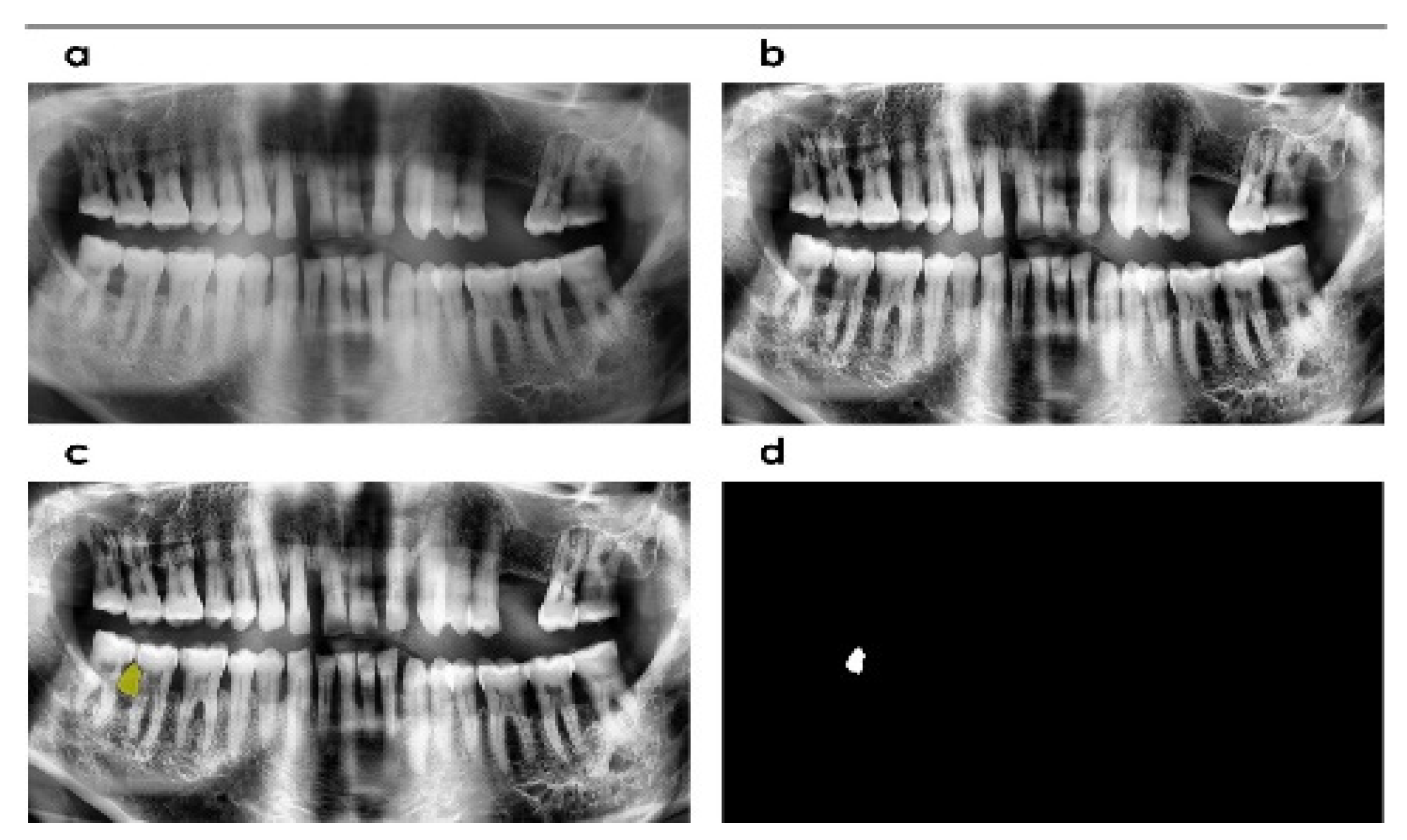
Pre-processing of images was necessary to improve the performance of the system. Contrast Limited Adaptive Histogram Equalization (CLAHE) increased radiographic contrast in the current analysis. The drawback of over-amplifying noise by adaptive histogram equalization is overcome by this method. It avoids over-amplification by clipping the histogram to a predetermined value [18]. It considers the image based on individualized tiles whose histogram is matched by a distribution parameter [12,19]. The neighboring tiles are combined using bilinear interpolation to avoid over-amplification. The salient image components were made more noticeable by increasing contrast (Figure 2).

2.4. Localization and Angle Estimation

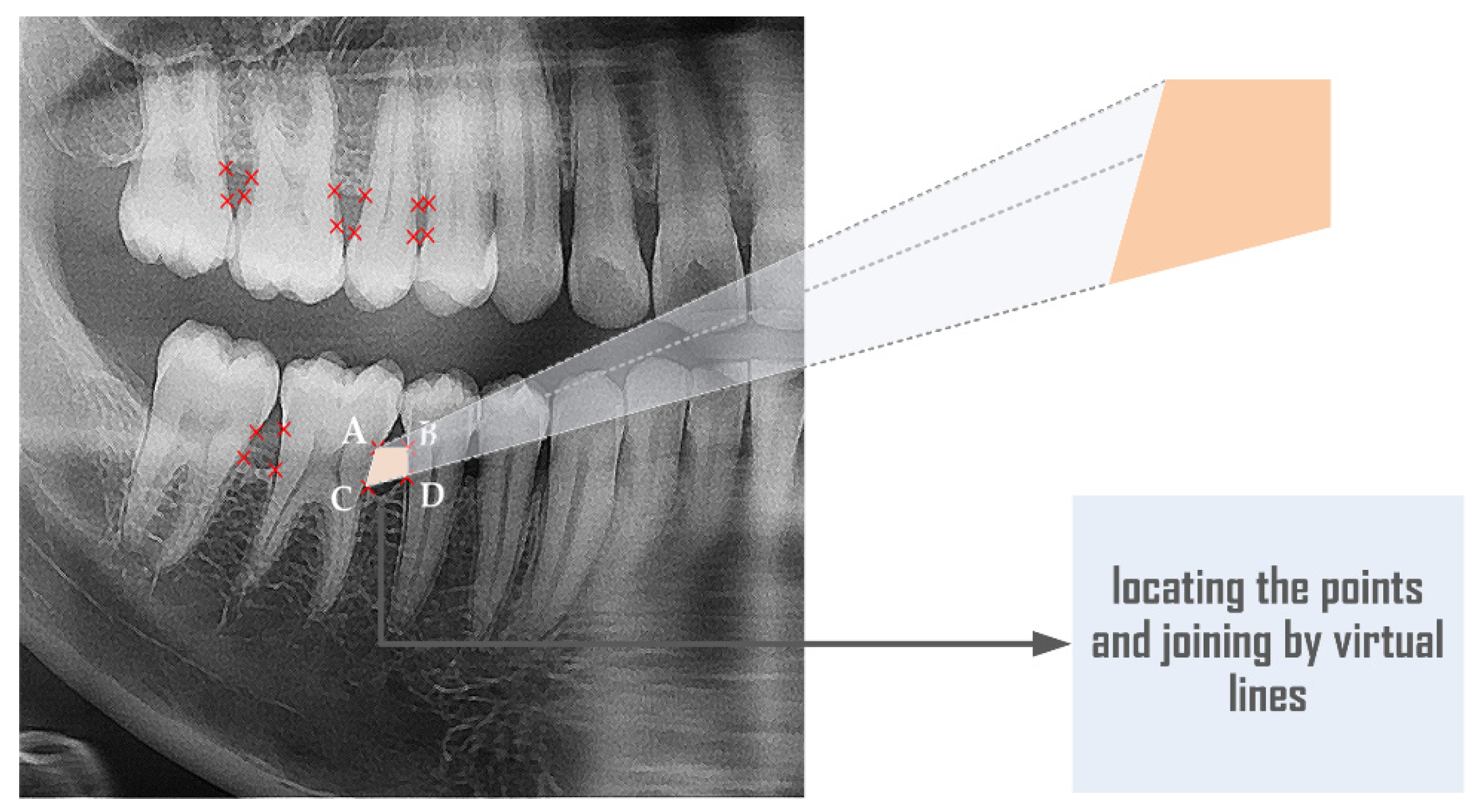
In the present study, the localization of points of interest on the alveolar crest and cementoenamel junction (CEJ) was performed in the radiographic imagery. Their coordinates were obtained from software programming. In Figure 3, points A and B are the cementoenamel junction points, and points C and D designate the alveolar crest meeting at the root surface, termed here as the specific amber line (SAL). Points A, B, C, and D are connected by virtual lines, and the tangent of the angle between them is measured using (1), which is then converted to degrees using (2). The results obtained are the alveolar bone loss angle value.
z = t a n 1 ( ( y 2 y 1 ) ( x 2 x 1 ) ) t a n 1 ( ( y 4 y 3 ) ( x 4 x 3 ) )
a n g l e = z ( 180 π )
Here, (x1, y1), (x2, y2), (x3, y3), and (x4, y4) are the coordinates of points A, B, C, and D.

2.5. Segmentation

The image under analysis was subjected to an active contour by providing an initial seed point. The active contour then expands to the nearest available boundaries (Figure 4c), thus enabling the segmentation of the area of the alveolar space. Here, four iterations were used for the no-disease radiographs, whereas for the periodontitis radiographs, 20 iterations were used. The binary image of the segmented area (Figure 4d) gives the alveolar space. The extracted region is calculated in terms of pixels from the binary image. It is then converted to units of millimeters by using a conversion factor as given in (3).
Area   in   mm = pixels     96   μ m 1000
In the conversion factor, 96 µm is considered since this is the conversion factor utilized in the device from which radiographs were collected.

2.6. Manual Measurement (Ground Truth)

Manual measurement was conducted by locating the region of interest in the hard and soft copies of individual patients’ orthopantomography (OPGs). The radiographs showing periodontitis and non-periodontitis were separately measured by a dental specialist (Periodontist) (SK) (Figure 3). The manual measurements were completed on hard and soft copies to compare whether the measured area and the angle corresponded to the points marked by the examiners on a soft computerized copy. The matching ensured no distortion of the image dimensions in the soft copies as compared with the corresponding hard copy OPGs. Thereafter, the location of the points was determined by two separate examiners (SK, SM) in software (Planmeca Romexis 3.8.1.R, PLANMECA, Helsinki, Finland). The software provided the measurement of the distance between the two points. Hence, the area and the angle were calculated manually. The mean of the two-examiner values was considered to be the ground truth value.

2.7. Statistical Analysis

The descriptive of the area and the angle measure by manual method (GT) and the computer software were tabulated to assess the normality between the scores. To determine the agreement in values of the alveolar space area and alveolar crest angle for ground truth versus a computational tool, a Bland–Altman plot was constructed. The ROC curve was plotted to determine the sensitivity and specificity of the values estimated by the computer tool. The null hypothesis of no significant difference was proposed for statistical analysis, and a p-value less than 0.05 was considered statistically significant. All statistical tests were conducted using jamovi software (The Jamovi project. 2020; R Core Team. 2021) [20,21].

3. Results

3.1. Alveolar Space Area

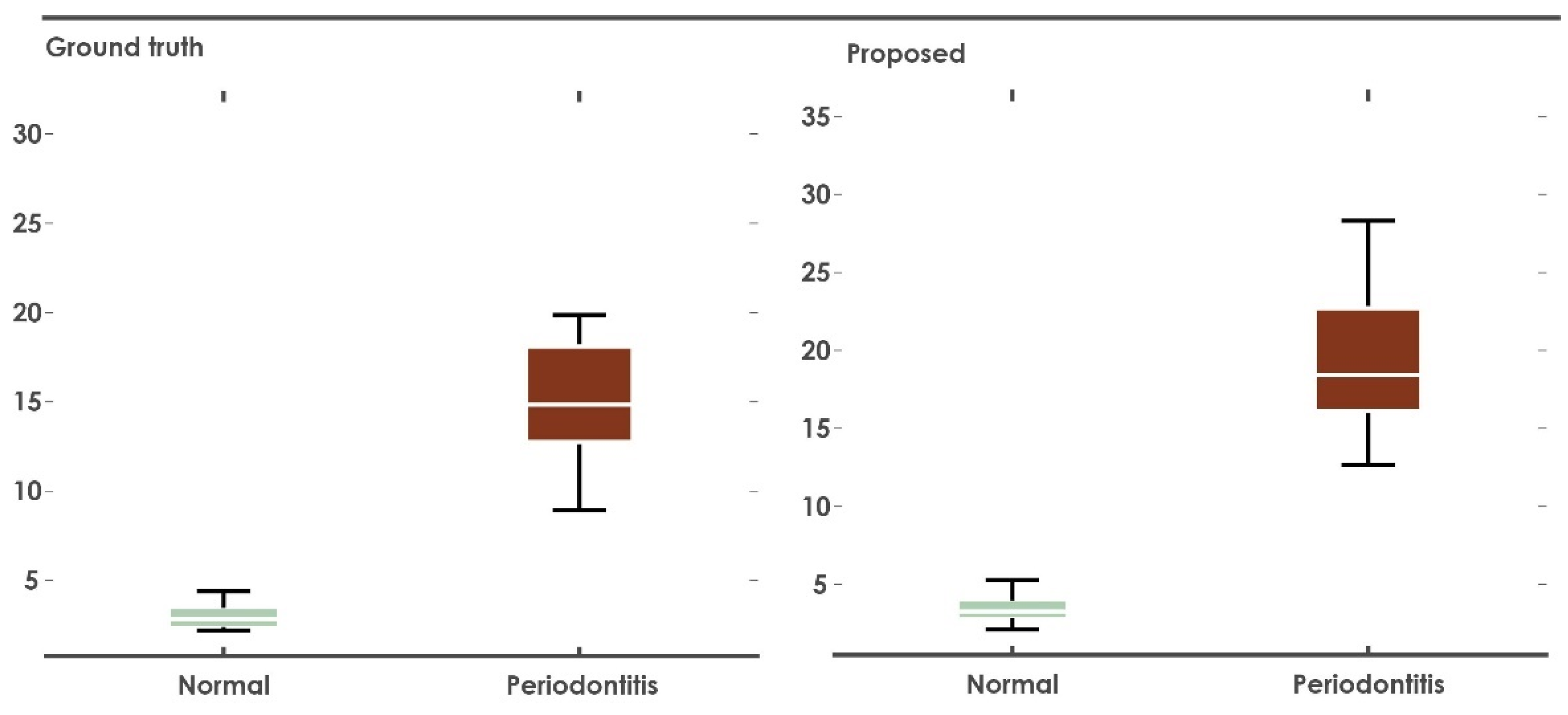
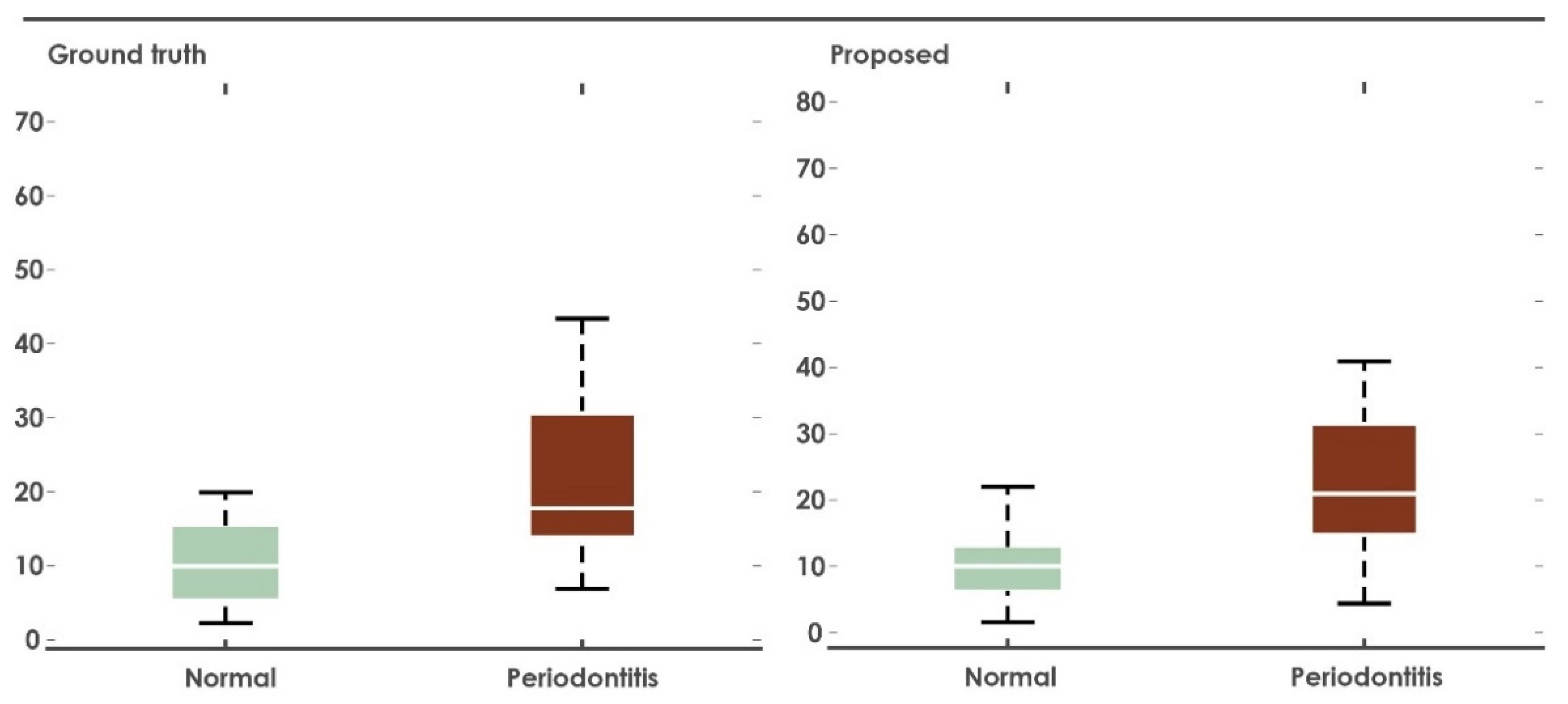
The alveolar space area as estimated in the radiographs of the periodontitis versus non-periodontitis groups is tabulated in Table 1. The dentist-assessed median values in non-periodontitis and periodontitis groups were 2.84 and 14.8, with standard deviations (σ) of 0.715 and 5.56, respectively. The median values evaluated by the computational tool (CT) of the alveolar space area in non-periodontitis and periodontitis groups were 3.26 and 18.4, with standard deviations (σ) of 0.73 and 6.03, respectively. The Shapiro–Wilk test showed a value p < 0.05; hence the null hypothesis assumption of normal distribution was rejected. The estimated area in the radiographs of the periodontitis group was much larger than the non-periodontitis group in both the computer tool and the manual method. The values of the alveolar space area could be distinguished between each other and can be analyzed using a box plot (Figure 5).

3.2. Alveolar Crest Angle

The descriptive parameters of the alveolar crest angle as estimated in the radiographs of periodontitis and the non-periodontitis groups are tabulated in Table 1. The median of the assessment by the dentist in non-periodontitis and periodontitis groups were 9.95 and 17.8, with standard deviations (σ) of 7.35 and 16.5, respectively. The medians of the assessment by the computational tool (CT) of the alveolar crest angle in non-periodontitis and periodontitis groups were 10 and 21, with standard deviations (σ) of 7.73 and 17.5 respectively. The values of the alveolar space area could be distinguished between each other and can be analyzed using a box plot (Figure 6).

3.3. Analysis of Agreement

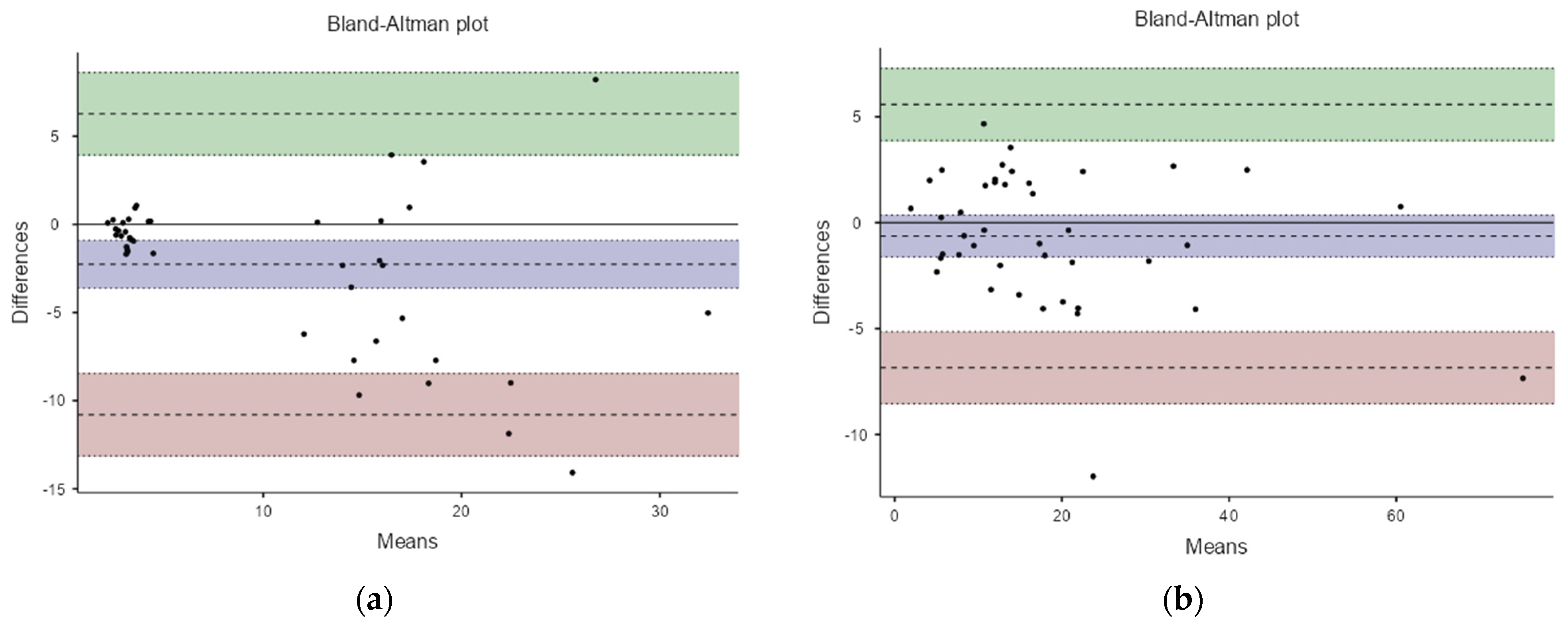
The Bland Altman (B&A) analysis to measure the agreement between the ground truth and the computer tool showed a mean of the differences (bias) of −2.26, with an upper and lower limit of 6.27 and −10.8 in the alveolar space area (ASA) (Figure 7a), and a mean of the differences (bias) of −0.633 with an upper and lower limit of 5.58 and −6.845 in alveolar crest angle (ACA) group (Figure 7b). More than 95% of all of the parameters were within the limit of agreement in the B&A plot. Clinically, the bias value of −2.26 or −0.633 would not affect the measurement of the alveolar space area by the computer tool method. Thus, the analysis showed the ground truth and computer tool to be in good agreement.

3.4. ROC Curve

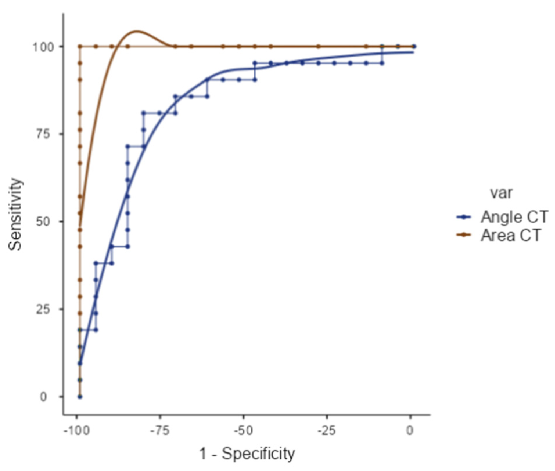
The ROC curve was used to measure the efficiency of the computer tool to detect the disease in a patient (Figure 8). The alveolar space area (ASA) showed a 100% sensitivity and specificity at a score at the cutoff point of 12.672 and an AUC (area under the curve) value of one, with a metric score of two (Table 2). The alveolar crest angle (ACA) of 13.672 degrees showed a maximum sensitivity and specificity (%) each of 80.95 with an AUC value of 0.828 and a metric score of 1.62 (Table 3 and Table 4).

4. Discussion

Snakes and active contours used in the present study have also been used for obtaining boundaries in MRI image segmentation by developing fast global minimization [22]. Snake functions work by minimizing the energy function to deform the curve [23]. However, conventional snakes have difficulty minimizing boundary concavities. This flaw was eliminated by using fast global minimization.
A template recognition software for identifying the teeth and calculating the teeth area from the face image has been developed [14]. This software considers four teeth for identity matching using the Hybrid differential method and membership function algorithms. An automated dental identification system (ADIS) has been built, and this can be used for teeth extraction from patient radiographs. Two-step thresholding (iterative and adaptive) has been adopted in this method. The seam carving technique was used for segmentation, offering the lowest failure rate [15]. Specific treatments in orthodontics can be performed by planning and computational simulation. These treatments can be completed by the 3D modeling of teeth and alveolar bone involving two-step segmentation; the first segmentation was made between the connected area of the tooth and alveolar bone using the global convex level-set model. Then, a random transform was used to separate individual teeth and alveolar bone. Cartesian coordinates can extract the 3D space between the teeth [16].
The digital image analyzer (DIA) was modified in a study by adding a periodontal intrabony defect angle. The method showed high sensitivity and specificity for detecting the cementoenamel junction and the crest of the alveolar bone [11]. MATLAB has been incorporated to locate the jawbone sites of patients before and after implant placement [24]. The vital image attributes that were obtained to assess implant placement accuracy were the mean gray level (MGL), standard deviation of gray levels (SDGL), coefficient of variation (CV), entropy (En), contrast, correlation (Cor), and angular second moment (ASM). This software requires training to understand, and the dentist has an equal role. Similarly, other studies have been done utilizing machine and deep learning for detection of the alveolar bone loss. However, these require the computer to be trained with many data sets before implementing the code. The various studies have been summarized in Table 5, including recent research using machine and deep learning platforms.
The tool developed in the present study does not require much training; however, the dentist must locate the CEJ and the alveolar crest. The use of the radiograph is to estimate and analyze the health of the hard tissue. Therefore, instead of measuring mesial and distal lengths, as computed in several studies [25,26], the area measured in our study provided an entirely new perspective on bone loss.
Automatic detection of the CEJ has been carried out by previous research in IOPAs [5,15]. In the present study, we have tried to provide a tool for screening patients’ OPGs showing bone loss. The OPG would serve as a better screening tool for periodontal disease. During periodontal disease screening, OPG is usually considered before full-mouth IOPA. Hence, the available OPG would serve as a preliminary assessment of the patient alveolar bone loss. After that, this method can be applied to IOPA radiographs at a specific region of interest. The paradigm described in this study could be evaluated by descriptive research and can be a vital aspect of any assessment.
Published studies have shown various techniques for estimating the interdental area and the localization of the CEJ [5]. They have estimated the area as determined by a dentist (utilized as ground truth) and compared it to the software estimation. The area obtained was in the intensity range. Thus, these articles showed an approximate and automated assessment of areas. The above studies mapped the lost alveolar bone apical site to the interdental region at the apex of the root surface. However, it must be noted that the alveolar bone lost as detected by the radiographs is a two-dimensional projection of a three-dimensional structure. Therefore, radiographs provide a better view of bone loss in the interdental region than any other region. If three-dimensional bone loss must be assessed, then instead of using the OPG tool, it is better to use cone-beam computed tomography (CBCT) images of dentition.
During regeneration, an increase in bone height occurs throughout the interdental region. Although soft tissue changes are detected at the mesial and distal sites of the tooth, hard tissue growth of the alveolar bone occurs throughout the interdental aspect, which is recorded in the radiographs. The computation of the alveolar space area by the active contour is accurate. It provides a good picture of total bone loss, which would be assistive as a prognostic factor. Software assessment can be a valuable tool, as it saves time and provides accurate and automatically computable data for recordkeeping.
In patients lacking periodontal disease, the distance from CEJ to bone crest within the normal range is less than 1.2 mm–1.9 mm [27]. However, no studies have described the interdental area that determines the overall amount of bone gain. Our study has shown the alveolar space area within 12.672 as the cutpoint to provide a maximum sensitivity and specificity estimate. The angle calculated in previous studies at the defect site, where the vertical bone defect could be observed, was termed the bone defect angle, or the BDA. However, the drawback of this paradigm is that bone defect morphology does not consider the cementoenamel junction. If there is bone fill in the future after treatment, then the angle would be obliterated. In the present study, the bone/defect type considered the cementoenamel junction between the adjacent teeth and/the alveolar crest line. The cut point of the angulation provides the maximum sensitivity, and the specificity estimate is 13.627. This would not only assist in measuring the present angulation but would also help in providing the prognostic angulation based on bone defect fill. The angulation reduces following a bone fill or, in the case of advancing periodontitis, depending on bone loss. The aim of the treatment could depend on the type of bone defect based on the assessed angulation by the new tool as compared to the old means of measurement.
Dentists have been using the old tool to measure the bone defect, but it measures only the bone defect angle and cannot measure the horizontal bone loss. With the help of the MATLAB software platform, the present tool computes the alveolar space area and alveolar crest angle with assistance from a dentist after he/she locates the vital points. There is also an improvement in the overall accuracy of the angulation and area measurement. In addition, it is considered to have better diagnostic and prognostic value. In terms of patient perspective, those with periodontal disease could understand the overall improvement in the efficiency of treating bone loss, assessing alveolar bone deficiency, and determining the overall health status of alveolar bone. In addition, it could be a vital tool to assess the overall bone loss after treatment in the phase of supportive periodontal therapy.
Although the present study fulfilled the objectives, the tool overestimates the amount of alveolar bone loss in the interdental region, as the crest of the alveolar bone is apical to the CEJ in healthy individuals by 0.4 mm to 1.9 mm. Further, the measurement does not include the intrasurgical measures or CBCT along with clinical co-relation that could provide very accurate bone defect measurement [28].
The advantage of this tool is that it provides the area and angle which includes the cementoenamel junctions of the adjacent teeth and the crest of the alveolar bone. Post-treatment angulation and the area can be compared to the interdental dimension, closely related to the amount of radiolucency corresponding to the degree of lost alveolar bone. It provides a general radiographic difference between the patients with disease versus the healthy state. It gives an estimated value that can be computed using a basic algorithm, and the dentist retains an essential role in the process.
Future studies could include the development of a fully-automated algorithm that detects the cementoenamel junction and estimates the angle and area that could be built. In addition, accuracy could be improved by combining patient intraoral clinical data with radiographic data and developing a combined bone loss and soft tissue loss assessment tool. These could improve the diagnostics and predict the prognosis of alveolar bone loss in patients with periodontal disease.

5. Conclusions

The alveolar space area and alveolar crest angle measured using a computational tool were of equal value compared to the ground truth. There was no statistically significant difference between the two methods of estimation. Clinically, the alveolar space area and alveolar crest angle impact the assessment of overall bone deficiency and can be an essential tool in diagnosing and evaluating the prognosis of the disease. Further, the detection method of area and angulation mentioned in the present study provides a better indication of defect type. In future work, detecting alveolar bone defects (BDA), including the CEJ of the adjacent teeth, can be a practical alternative.

Author Contributions

Conceptualization, M.M., D.G.B. and S.K.; Data curation, M.M. and S.K.; Formal analysis, M.M., D.G.B., S.K., A.G. and S.M.; Investigation, M.M. and S.K.; Methodology, M.M., D.G.B., S.K., U.R., A.G. and W.Y.C.; Project administration, M.M. and U.R.; Resources, M.M.; Software, M.M., D.G.B. and A.G.; Supervision, M.M., U.R. and A.G.; Validation, M.M. and U.R.; Writing—original draft, D.G.B., M.M., U.R. and S.K.; Writing—review and editing, M.M., S.K., U.R., W.Y.C., R.V., P.G., E.J.C. and U.R.A. All authors have read and agreed to the published version of the manuscript.

Funding

This research received no external funding.

Institutional Review Board Statement

Not applicable.

Informed Consent Statement

Not applicable.

Data Availability Statement

Data is contained within the article.

Acknowledgments

I would like to acknowledge the assistance of the department of Periodontology and the department of Oral Medicine for their constant support during the entire duration of the project.

Conflicts of Interest

The authors declare no conflict of interest.

References

  1. Greenstein, B.; Frantz, B.; Desai, R.; Proskin, H.; Campbell, J.; Caton, J. Stability of treated angular and horizontal bony defects: A retrospective radiographic evaluation in a private periodontal practice. J. Periodontol. 2009, 80, 228–233. [Google Scholar] [CrossRef]
  2. D’Ercole, S.; D’Addazio, G.; Di Lodovico, S.; Traini, T.; Di Giulio, M.; Sinjari, B. Porphyromonas Gingivalis Load is Balanced by 0.20% Chlorhexidine Gel. A Randomized, Double-Blind, Controlled, Microbiological and Immunohistochemical Human Study. J. Clin. Med. 2020, 9, 284. [Google Scholar] [CrossRef] [PubMed] [Green Version]
  3. Teeuw, W.; Coelho, L.; Silva, A.; Van Der Palen, C.; Lessmann, F.; Van der Velden, U.; Loos, B. Validation of a dental image analyzer tool to measure alveolar bone loss in periodontitis patients. J. Periodontal. Res. 2009, 44, 94–102. [Google Scholar] [CrossRef]
  4. Lin, P.-L.; Hsu, H.; Huang, P.-Y.; Huang, P.-W.; Chen, P. Alveolar bone-loss area localization in periapical radiographs by texture analysis based on fBm model and GLC matrix. In Proceedings of the 2014 IEEE International Symposium on Bioelectronics and Bioinformatics (IEEE ISBB 2014), Chung Li, Taiwan, 11–14 April 2014. [Google Scholar]
  5. Moutinho, R.; Coelho, L.; Silva, A.; Lobo Pereira, J.; Pinto, M.; Baptista, I. Validation of a dental image-analyzer tool to measure the radiographic defect angle of the intrabony defect in periodontitis patients. J. Periodontal. Res. 2012, 47, 695–700. [Google Scholar] [CrossRef]
  6. Lin, P.; Huang, P.; Huang, P. Automatic methods for alveolar bone loss degree measurement in periodontitis periapical radiographs. Comput. Methods Programs Biomed. 2017, 148, 1–11. [Google Scholar] [CrossRef] [PubMed]
  7. Sinibaldi, R.; Conti, A.; Sinjari, B.; Spadone, S.; Pecci, R.; Palombo, M.; Komlev, V.S.; Ortore, M.G.; Tromba, G.; Capuani, S.; et al. Multimodal-3D imaging based on μMRI and μCT techniques bridges the gap with histology in visualization of the bone regeneration process. J. Tissue Eng. Reg. Med. 2018, 12, 750–761. [Google Scholar] [CrossRef]
  8. Krois, J.; Ekert, T.; Meinhold, L.; Golla, T.; Kharbot, B.; Wittemeier, A.; Dörfer, C.; Schwendicke, F. Deep Learning for the Radiographic Detection of Periodontal Bone Loss. Sci. Rep. 2019, 9, 1–6. [Google Scholar] [CrossRef]
  9. Lee, J.-H.; Kim, D.-H.; Jeong, S.-N.; Choi, S.-H. Diagnosis and prediction of periodontally compromised teeth using a deep learning-based convolutional neural network algorithm. J. Periodontal. Implant Sci. 2019, 48, 114–123. [Google Scholar] [CrossRef] [PubMed] [Green Version]
  10. Chang, H.J.; Lee, S.J.; Yong, T.H.; Shin, N.Y.; Jang, B.G.; Kim, J.E.; Huh, K.H.; Lee, S.S.; Heo, M.S.; Choi, S.C.; et al. Deep learning hybrid method to automatically diagnose periodontal bone loss and stage periodontitis. Sci. Rep. 2020, 10, 1–8. [Google Scholar]
  11. Woods, R.E.; Eddins, S.L.; Gonzalez, R.C. Digital Image Processing Using MATLAB; Institute of Geodesy and Photogrammetry, ETH: Zurich, Switzerland, 2009. [Google Scholar]
  12. Zaki, H.A.; Hoffmann, K.R.; Hausmann, E.; Scannapieco, F.A. Is radiologic assessment of alveolar crest height useful to monitor periodontal disease activity? Dent. Clin. 2015, 59, 859–872. [Google Scholar] [CrossRef] [Green Version]
  13. Shang, J.; Zheng, X.; Zhang, Y. A Teeth Identification Method Based on Fuzzy Recognition. In Proceedings of the 2010 Second International Conference on Intelligent Human-Machine Systems and Cybernetics, Nanjing, China, 26–28 August 2010; pp. 271–275. [Google Scholar]
  14. Al-Sherif, N.; Guo, G.; Ammar, H.H. A new approach to teeth segmentation. In Proceedings of the 2012 IEEE International Symposium on Multimedia, Irvine, CA, USA, 10–12 December 2012; pp. 145–148. [Google Scholar]
  15. Gan, Y.; Xia, Z.; Xiong, J.; Li, G.; Zhao, Q. Tooth and alveolar bone segmentation from dental computed tomography images. IEEE J. Biomed. Health Inf. 2018, 22, 196–204. [Google Scholar] [CrossRef]
  16. Winter, G.B. Ch. 7: Radiographic interpretation of the Ossistructure of the impacted mandibular third molar. In Principles of Exodontia as Applied to the Impacted Mandibular Third Molar: A Complete Treatise on the Operative Technic with Clinical Diagnoses and Radiographic Interpretations; American medical Book Company: St. Louis, MI, USA, 1926; p. 142. [Google Scholar]
  17. Zuiderveld, K. Chapter 5. Contrast limited adaptive histogram equalization. In Graphics Gems, 4th ed.; Heckbert, P.S., Ed.; Academic Press Professional Inc.: San Diego, CA, USA, 1994; pp. 474–485. [Google Scholar]
  18. Pizer, S.M.; Amburn, E.P.; Austin, J.D.; Cromartie, R.; Geselowitz, A.; Greer, T.; ter Haar Romeny, B.; Zimmerman, J.B.; Zuiderveld, K. Adaptive histogram equalization and its variations. Comput. Vis. Graph. Image Process. 1987, 39, 355–368. [Google Scholar] [CrossRef]
  19. The Jamovi Project. Jamovi. (Version 2.0) [Computer Software]. 2021. Available online: https://www.jamovi.org (accessed on 25 January 2020).
  20. Thiele, C. cutpointr: Determine and Evaluate Optimal Cutpoints in Binary Classification Tasks. [R package]. Available online: https://cran.r-project.org/package=cutpointr (accessed on 25 January 2020).
  21. Tran, T.-T.; Lee, P.-L.; Pham, V.-T.; Shyu, K.-K. MRI image segmentation based on fast global minimization of snake model. In Proceedings of the 2008 10th International Conference on Control, Automation, Robotics and Vision, Hanoi, Vietnam, 17–20 December 2008; pp. 1769–1772. [Google Scholar]
  22. Kass, M.; Witkin, A.; Terzopoulus, D. Snakes: Active Contour Models. Int. J. Comput. Vis. 1988, 1, 312–331. [Google Scholar] [CrossRef]
  23. Mundim, M.B.; Dias, D.R.; Costa, R.M.; Leles, C.R.; Azevedo-Marques, P.M.; Ribeiro-Rotta, R.F. Intraoral radiographs texture analysis for dental implant planning. Comput. Methods. Programs. Biomed. 2016, 136, 89–96. [Google Scholar] [CrossRef] [PubMed]
  24. Hausmann, E.; Allen, K.; Dunford, R.; Christersson, L. A reliable computerized method to determine the level of the radiographic alveolar crest. J. Periodontal Res. 1989, 24, 368–369. [Google Scholar] [CrossRef] [PubMed]
  25. Hausmann, E.; Allen, K.; Clerehugh, V. What alveolar crest level on a bite-wing radiograph represents bone loss? J. Periodontol. 1991, 62, 570–572. [Google Scholar] [CrossRef]
  26. Lin, P.; Huang, P.; Huang, P.; Hsu, H. Alveolar bone-loss area localization in periodontitis radiographs based on threshold segmentation with a hybrid feature fused of intensity and the H-value of fractional Brownian motion model. Comput. Methods Programs Biomed. 2015, 121, 117–126. [Google Scholar] [CrossRef]
  27. Khocht, A.; Janal, M.; Harasty, L.; Chang, K.-M. Comparison of direct digital and conventional intraoral radiographs in detecting alveolar bone loss. J. Am. Dent. Assoc. 2003, 134, 1468–1475. [Google Scholar] [CrossRef]
  28. Eickholz, P.; Kim, T.-S.; Benn, D.K.; Staehle, H.J. Validity of radiographic measurement of interproximal bone loss. Oral Surg. Oral Med. Oral Pathol. Oral Radiol. Endod. 1998, 85, 99–106. [Google Scholar] [CrossRef]
  29. Cha, J.-Y.; Yoon, H.-I.; Yeo, I.-S.; Huh, K.-H.; Han, J.-S. Peri-Implant Bone Loss Measurement Using a Region-Based Convolutional Neural Network on Dental Periapical Radiographs. J. Clin. Med. 2021, 10, 1009. [Google Scholar] [CrossRef]
  30. Sharma, H.; Dahiya, P.; Gupta, R.; Kumar, M.; Melwani, S.R.; Kachroo, L. Comparison of conventional and digital radiographic techniques for the assessment of alveolar bone in periodontal disease. Indian J. Dent. Sci. 2019, 11, 138. [Google Scholar] [CrossRef]
  31. Desai, S.R.; Shinde, H.H. Correlation of interdental and inter-radicular bone loss—Radiographic assessment. Bone 2008, 2, 35–37. Available online: https://www.semanticscholar.org/paper/bbba095076774bb4f7b477081655de818ea80fea (accessed on 10 December 2019).
  32. Talaiepour, A.R.; Panjnoush, M.; Soleimanishayeste, Y.; Abesi, F.; Sahba, S. A Survey on the Accuracy of Radiovisiography in the Assessment of Interproximal Intrabony Defects. Front. Dent. 2005, 2, 29–31. [Google Scholar]
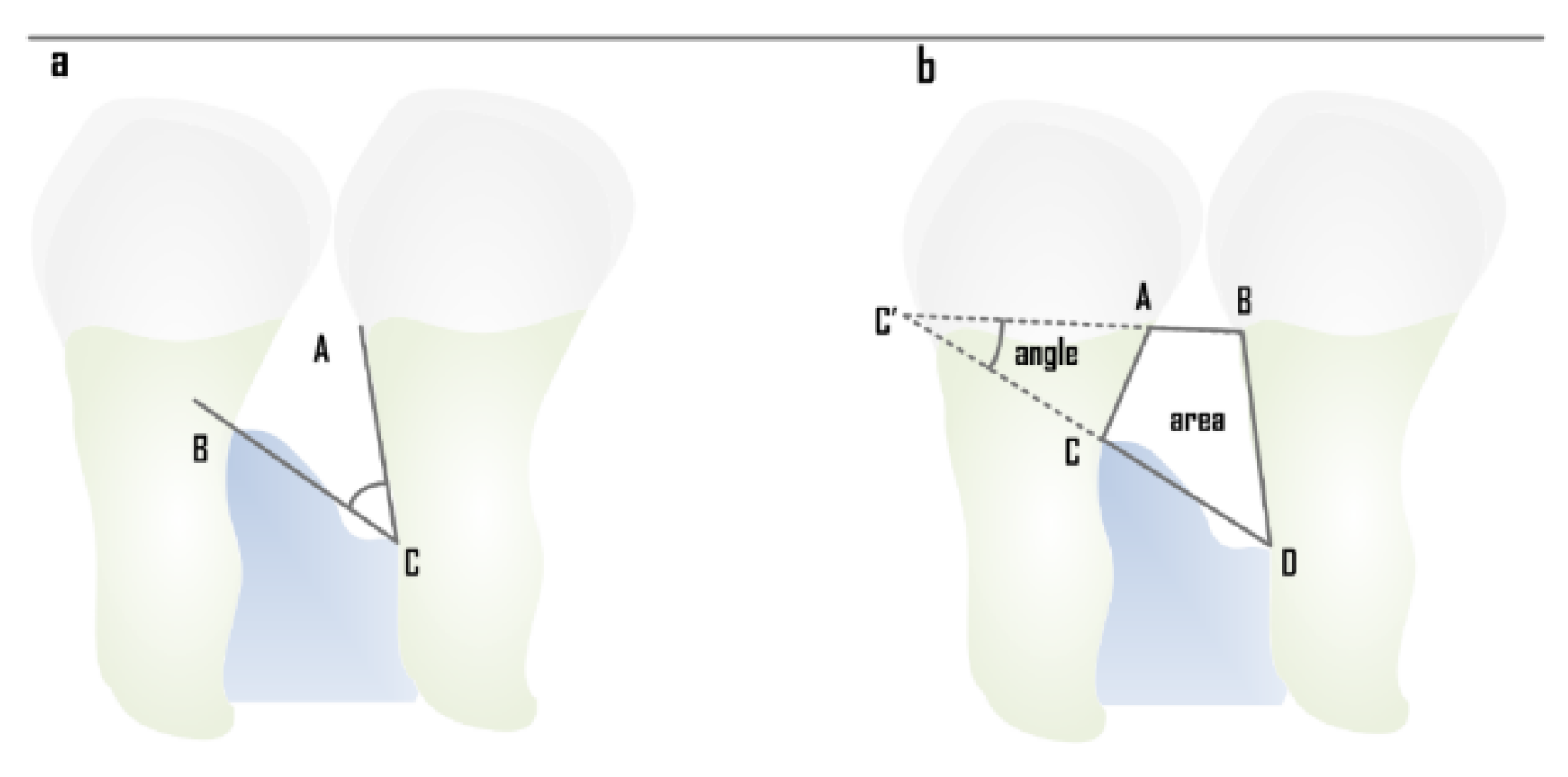
Figure 1. (a) Conventional defect angle measurement between ACB (BDA), (b) Modified measurement of the defect angle AC’C (Alveolar crest angle—ACA), and defect area within ABDC (Alveolar space area—ASA).
Computation 10 00008 g001
Figure 2. Overview of the proposed approach.
Computation 10 00008 g002
Figure 3. Alveolar space area that is obtained following localization of points on the alveolar crest line and on the CEJ between the adjacent teeth.
Computation 10 00008 g003
Figure 4. (a) Radiograph before image enhancement, (b) Image enhancement by CLAHE, (c) Image segmentation to compute the alveolar space between two intermediate teeth, and (d) binary image of segmented part.
Computation 10 00008 g004
Figure 5. Box plot of ASA values obtained by computer tool and ground truth in radiographs of normal and periodontitis groups.
Computation 10 00008 g005
Figure 6. Box plot of ACA values obtained by computer tool and ground truth in radiographs of normal and periodontitis groups.
Computation 10 00008 g006
Figure 7. (a) Bland Altman (B&A) Plot between the ground truth and the computer tool of the alveolar space area with an upper and lower limit of agreement of 6.27 and −10.8, with 95% of the values lying within the limit of agreement; (b) B&A Plot of the periodontitis group. Upper and lower limits are 5.58 and −6.845, with 95% of the values lying within the limit of agreement.
Computation 10 00008 g007
Figure 8. ROC curve plot of the alveolar space area (ASA) and the Alveolar Crest angle (ACA) of the values as estimated by the computer tool (CT).
Computation 10 00008 g008
Table 1. Descriptive of Alveolar space area and the alveolar crest angle as estimated by the computer tool and the ground truth in patients with or without periodontitis.
CT NP AreaCT P AreaGT NP AreaGT P AreaGT NP AngleCT NP AngleGT P AngleCT P Angle
N2121212121212121
Mean3.4220.22.9716.111.411.524.425.7
Median3.2618.42.8414.89.9510.017.821.0
SD0.7306.030.7155.567.357.7316.517.5
Minimum2.1112.72.198.942.261.596.884.40
Maximum5.2834.94.4030.934.535.571.578.8
Shapiro–Wilk W0.9580.8740.8570.8390.8790.8410.7900.832
Shapiro–Wilk p0.4700.0110.0060.0030.0140.003< 0.0010.002
Table 2. The Sensitivity and Specificity cutoff values of the Alveolar space area (ASA) as estimated by the Computer Tool (CT).
CutpointSensitivity (%)Specificity (%)AUCMetric Score
5.28100%95.24%1.001.95
12.672100%100%1.002.00
14.49695.24%100%1.001.95
Table 3. The Sensitivity and Specificity cutoff values of the Alveolar crest Angle (ACA) as estimated by the Computer Tool (CT).
CutpointSensitivity (%)Specificity (%)AUCMetric Score
12.294885.71%71.43%0.8281.57
13.106180.95%76.19%0.8281.57
13.62780.95%80.95%0.8281.57
15.139576.19%80.95%0.8281.62
16.587371.43%85.71%0.8281.57
Table 4. Sensitivity and specificity table of the angle and the area score that gives the maximum true negative and the true positive values of the estimates.
Scale: Area CT|Score: 12.672
DECISION BASED ON MEASURE
NegativePositive
CRITERIONNegative21 (TN)0 (FP)
Positive0 (FN)21 (TP)
Scale: Angle CT|Score: 13.627
DECISION BASED ON MEASURE
NegativePositive
CRITERIONNegative17 (TN)4 (FP)
Positive4 (FN)17 (TP)
Table 5. Various studies showing the estimation of alveolar bone loss using different methods.
NameStudy DesignMethodResultsConclusions
Cha, J-Y et al., 2021 [29]708 periapical dental radiographic images,
508—Training 100—validation, 100—test.
R-CNN vs. 2 dentists (1 Dental practitioner and another Oral and maxillofacial radiologist)
The mean object Key-point similarity (OKS)—dentist vs. R-CNN.
Mean OKS Dentist—0.9012
Mean OKS Model—0.8885
Dentist vs. Model p-value 0.4095
There is no difference between the dentist and the R-CNN in diagnosing and categorizing peri-implant bone loss.
Krois et al., 2019 [8]350 panaromic dental radiographic Images,
1750 image segments; 350 for validation and 1400 for training
CNNs vs. 6 dental practitioners to detect periodontal bone loss (PBL)Mean SD: 0.76 ± 0.06
t-test: p = 0.067.
Fleiss Kappa score of 0.52—moderate;
No difference between dentist and the CNN P = 0.067.
Sharma et al., 2019 [30]30 systemically healthy periodontitis patients with 100 interproximal sites.Conventional (intraoral periapical [IOPA] radiographs) vs. digital radiographs (radiovisiography [RVG]) vs. intrasurgical (IS) CEJ to the alveolar crest: Horizontal bone loss—4.38 ± 2.11, 4.26 ± 2.2, 4.67 ± 1.89
Vertical bone loss—8.23 ± 2.25, 8.25 ± 2.38, 7.79 ± 2.43
Both radiographic methods (conventional and digital) showed statistically nonsignificant results in comparison to IS measurements.
Lin et al., 2017 [6]Automatic Alveolar bone loss measurement system and cementoenamel junction (CEJ) localization.Local singularity and ABLifBM53% of the localization of the CEJ was within the 3-pixel deviation (appox. 0.15 mm) from GT and 90% have deviation within 9 pixels (approx. 0.44 mm) from GTThe method could automatically estimate the degree of alveolar bone loss and localize the cementoenamel junction.
Jae-hong et al., 2018 [8]Develop the computer assisted detection system based on deep convolution neural network (CNN) Algorithmdeep CNN architecture and self-trained network.Accuracy: 81.0%—Premolars Accuracy: 76.7%—MolarsThe algorithm used in this study gave the diagnosis and prognosis of the periodontitis tooth images.
Lin et al., 2015 [26]31 periodontitis IOPA radiographic imagesABLIfBm vs. threshold segmentation.True positive 92.5%
False positive: 14%
ABLIfBm outperforms the threshold segmentation method, and it could localize the alveolar bone loss effectively.
Moutinho et al., 2012 [5]60 teeth from 47 patientsConventional vs. digital using DIA tool: measurement of the defect angle (BDA)Interexaminer reliability: Intraclass Correlation Coefficient > 0.97
Intermethod reliability > 0.96.
There was no difference between the conventional method and the DIA tool for the radiographic measurement of intrabony defects.
Popova et al., 2008 [31]49 patients with vertical and horizontal bitewingRadiographic measurement and using the Williams periodontal probeInterdental bone loss:
4.18 to 5.54 mm is associated with interradicular bone loss with values of 0.45 to 1.33 mm.
Interradicular bone loss was associated with the progression of bone destruction in multirooted teeth.
Talaiepour et al., 2005 [32]32 radiographs of 56 periodontally diseased teethRVG (Radiovisiography) and intrasurgical methodRVG:
CEJ to BD: 6.803±3.589 mm
Intrasurgically (IS):
CEJ to BD: 6.492 ± 3.492 mm (p < 0.000).
Radiographic measurement overestimated the bone loss.
Khocht, et al., 2003 [27]25 Subjects
857 PA radiographs
315 Bitewing
Bone loss measurement in digital radiographs vs. conventional radiographsAlveolar bone level differed in intraoral direct digital compared to conventional. (p < 0.02).The digital radiographs showed a higher number of sites with bone loss than the conventional radiographs.
Eickholz and Hausmann 2000 [2]34 interproximal
bone loss in IOPAs
Linear measurement of intrabony defect vs. surgical measurementSurgical: CEJ-BD—9.15 ± 2.09,
AC-BD—5.15 ± 1.96,
Radiographic Measurement:
CEJ to BD—7.74 ± 2.11
AC-BD—3.97 ± 13.39 mm
The assessment of the bone loss was more accurate in surgical measurement than the radiographic measurement.
Eickholz et al., 1998 [28]62 standardized radiographs taken presurgically of 35 patients suffering from advanced periodontal disease.LMSRT (Computer assisted analysis system) vs. loupe CEJ-AC:
Loupe:0.86 ± 1.84 mm [p < 0.001]
LMSRT 0.58 ±1.86 mm [p < 0.005]
CEJ-BD:
loupe: 1.22 ± 2.33 mm [p < 0.001]
LMSRT: 0.80 ± 2.09 mm [p < 0.001]
LMSRT was better than loupes along with grid. Surgical method was the best.
Hausmann et al., 1991 [25]134 sites in Bitewing radiographs from 68 adolescents 13–14 years of age. 18 months apart were included in the studyMean radiographic distance from CEJ-to-crest distance (mm)Distance:
Baseline: 1.11 ± 0.37 mm
After 18 Months 1.19 ± 0.34 mm
No crestal bone loss is consistent with a range of radiographic CEJ-to-crest distance between 0.4–1.9 mm.
Publisher’s Note: MDPI stays neutral with regard to jurisdictional claims in published maps and institutional affiliations.