A Large Effective Touchscreen Using a Head-Mounted Projector

Graduate School of Science and Engineering, Saitama University, 255 Shimo-Okubo, Sakura-ku, Saitama 338-8570, Japan
*
Author to whom correspondence should be addressed.
Information 2018, 9(9), 235; https://doi.org/10.3390/info9090235
Submission received: 17 August 2018
/
Revised: 4 September 2018
/
Accepted: 8 September 2018
/
Published: 18 September 2018
(This article belongs to the Special Issue Wearable Augmented and Mixed Reality Applications)
Abstract
:In our previous work, we proposed a user interface in which a user wears a projector and a depth camera on his or her head and performs touch operations on an image projected on a flat surface. By using the head-mounted projector, images are always projected in front of the user in the direction of the user’s gaze. The image to be projected is changed according to the user’s head pose so as to fix the superimposed image on the surface, which realizes a large effective screen size. In this paper, we conducted an experiment for evaluating the accuracy of registration by measuring the positional and rotational errors between the real world and the superimposed image using our experimental system. As a result, the mean absolute errors of translation were about 10 mm when the user stopped his head, and the delay was estimated to be about 0.2 s. We also discuss the limitations of our prototype and show the direction of future development.
1. Introduction
In recent years, mobile devices, such as smartphones and tablets, and systems using large displays and keyboards, such as personal computer (PCs), have become widely used. While mobile devices have the advantage of portability, one problem is their small operating areas because of their small screens. In contrast, while systems using a large display and a keyboard have good operability, it is difficult to carry them around. Therefore, there is demand for systems that can realize both good portability and large operating areas.
As related work, there have been studies on user interfaces (UIs) using projectors [1,2,3,4,5]. By using a projector, it is possible to display an image on a large display area. By touching an image projected on a plane, a user can interact with the image. However, to increase the size of the display area, there is a constraint in terms of the installation locations, namely, that the projection plane and the projector should be separated by a large distance.
To solve this problem, there have been studies on peephole interaction using a handheld projector [6,7]. By changing the image to be projected according to the projector’s position and direction, it is possible to extend the display area. However, this approach has some problems; for example, one hand is busily occupied holding the projector, and images are not always projected in front of the user in his or her gaze direction.
On the other hand, there have been studies on UIs using a head-mounted projector that can constantly display images in front of the user [8,9,10,11,12,13,14,15]. In these studies, it is possible to present images in his or her gaze direction, since the projector is worn on the head. However, these systems were not made for extending the display area.
In our previous work, we proposed a user interface that projects images on a flat surface in front of the user by using a head-mounted projector [16]. With this approach, a large effective display area can be realized by changing the image to be projected according to the direction of the user’s head.
In this paper, we show the result of an experiment for evaluating the accuracy of registration by measuring the positional and rotational errors between the real world and the superimposed image using the experimental system. Based on the results, we also discuss the limitations of our prototype and show the direction of future development.
2. Related Work
2.1. UIs Using a Projector
There have been studies on UIs in which a user can interact with images projected on a flat surface, such as a table, by touching them with his or her fingers.
Roeber et al. developed the Canesta Projection Keyboard, a system in which a user can enter characters by touching a keyboard image projected by a projector installed on a flat surface [1]. Wilson et al. developed LightSpace, a system using projectors and depth cameras [2]. This system allows a user to interact with images projected on tables and walls by using projectors. Also, they have developed Beamatron, a system using a pan–tilt projector and a depth camera [3]. This system can project images at any point in the room. Harrison et al. developed OmniTouch, a system that consists of a pico-projector and a depth camera [4]. This system allows a user to interact with images projected on physical objects and his or her body by using a shoulder-worn projector. Dai et al. developed TouchScreenEverywhere, a system that consists of a small projector and a camera [5], allowing a user to perform touch operations on projected images.
These systems allow users to interact with the projected images. However, to increase the size of the display area, the projector should be separated by a large distance to the projection plane, which restricts the installation locations. In addition, there is a tradeoff between the size and brightness of projected images.
2.2. Peephole Interaction Using a Handheld Projector
In UIs using a handheld projector, there is a technique called peephole interaction, in which only part of a virtual information space, which is placed on a wall, a table, and so on, is seen through a peephole. A user can change the viewport to the position that he or she wants to see by changing the image to be projected according to the projection position, which realizes a large effective workspace.
Cao et al. developed a system that consists of a projector with buttons that has a shape similar to a flashlight [6]. A user can dynamically define and interact with multiple virtual information spaces that are embedded in the real world. Images projected by the projector are generated based on six degrees-of-freedom (6-DOF) pose information of the projector, which is tracked in 3D space. Also, a user can perform interactions, such as zooming and moving virtual objects and drawing lines in virtual spaces. Kaufmann et al. proposed a system consisting of a smartphone and a small projector that can project images so that only part of a larger information space is seen through a peephole [7]. This system obtains its own 3D poses by using the gyro sensor built into the smartphone, and the images to be projected are generated using the pose information of the smartphone. Also, the user can perform interactions, such as drawing lines, by touching the smartphone display.
In these studies, the systems can display a part of a larger virtual information space according to the displayed position of the image projected by the projector, but the images are not always in front of the user in his or her gaze direction.
2.3. UIs Using a Head-Mounted Projector
There are other UIs using a head-mounted projector that can constantly display images in front of the user in his or her gaze direction.
There are systems in which a user wears a projector and a half mirror for projecting images [8,9,10]. The images are projected from a projector placed at a position that is optically conjugate with the observer’s eyes, and the projected images are reflected on an object on which a retroreflective material is applied and reaches the eyes through the half mirror. Also, there are systems in which images from a projector are directly projected on a flat surface on which a retroreflective material is applied, without using a half mirror [11,12].
Yoshida et al. developed ARScope [13], which consists of a head-worn projector and a handheld device covered with a retroreflective material. The device looks transparent when a user looks into the device. Also, even if the user’s viewpoint position changes, the projected images seem to be consistent with the real world.
There are also UI systems that allow the user to interact, via gestures, with images projected on a surface, a real object, or a hand from a head-worn projector. Misty et al. developed Wear Ur World (WUW), a system that consists of a small projector and a camera, which projects images on physical objects from a head-worn projector and which allows interactions via gestures [14]. Tamaki et al. have developed Brainy Hand, a system that consists of a small camera, a laser projector, and an earphone worn in the ear that allows gesture-based interaction with images projected on the user’s palm by the projector [15].
In these studies, it is possible to present images in front of the user in his or her gaze direction. However, there are no studies that use a head-mounted projector for the purpose of projecting images in a wide area.
2.4. UIs Using a Head-Mounted Display
Head-mounted displays (HMDs) can also be used to constantly display images in front of the user in his or her gaze direction. Among them, Microsoft Hololens enables accurate plane detection and registration, since it is equipped with a depth camera, a head-tracking camera, and an inertial measurement unit (IMU). Xiao et al. developed a Hololens-based system called MRTouch [17], which enables users to perform touch input on surfaces in their environment. However, HMDs have a disadvantage that the users’ eyes are covered by the device, hindering their vision, which may cause a feeling of anxiety. In addition, eye fatigue sometimes occurs because of inconsistency between the convergence angle and focusing of the eyes. On the other hand, HMDs give a superior sense of immersion and ensure confidentiality, since the operations carried out by the user are not seen by someone else.
3. Proposed System
3.1. Overview
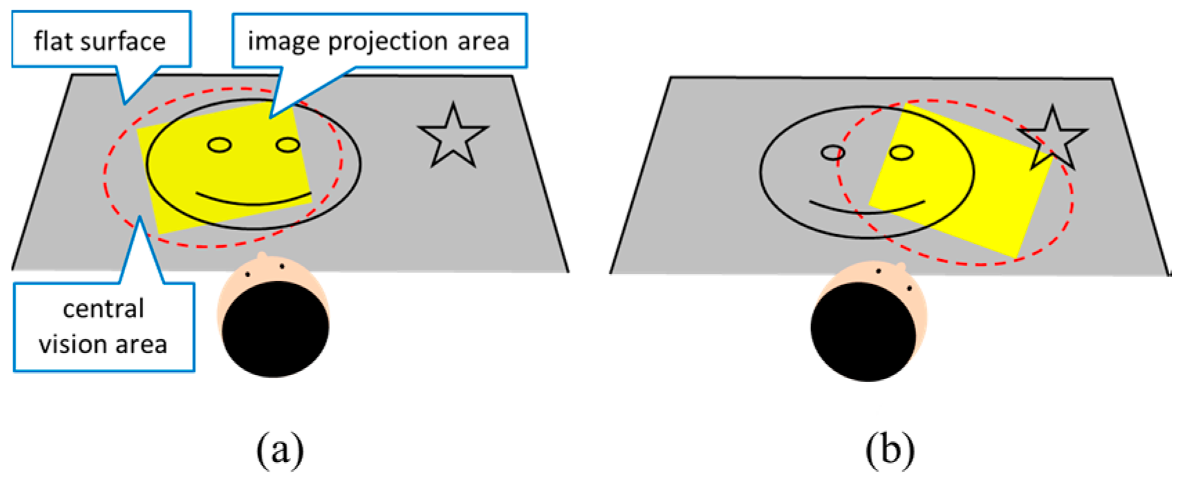
The user sits in a chair, wearing the system on his or her head, and the system projects images onto a flat surface, such as a table. Since the projector worn on the user’s head projects images in front of the user in his or her gaze direction, the images cover a large part of the user’s central area of vision, as shown in Figure 1. The image to be projected is changed according to the user’s head pose so as to fix the superimposed image on the surface. Thus, the system makes the flat surface act like a touch panel using the depth camera and realizes a large effective display area.
3.2. Experimental System
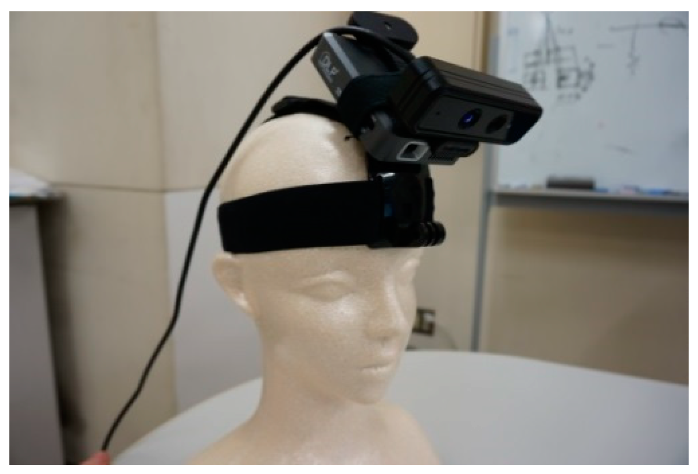
We created an experimental system using a mobile projector and a depth camera, as shown in Figure 2. The mobile projector was a Koolertron Mini Micro 640 × 480 HD DLP Home Theater Projector. The depth camera was a SoftKinetic DepthSense 325, which can acquire a 320 × 240 pixel depth map at 30 frames per second (fps) and can be used in a 15–100 cm range. Also, in this system, the depth camera and the projector were connected to a desktop PC (CPU: Intel Core i7-4790 3.6 GHz, RAM: 8 GB), which was used for calculations.
3.3. Superimposing Images
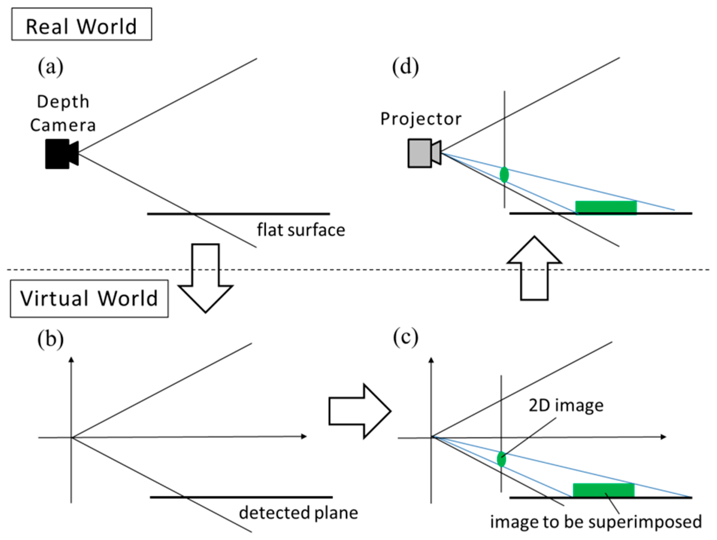
The system superimposes an image that looks to have the proper size and shape on a flat surface in the following way. First, the system obtains a three-dimensional (3D) scene in the real world by using the depth camera (Figure 3a) and performs plane estimation from the obtained 3D scene. Second, the system replicates, in a virtual world, the estimated plane (Figure 3b). Then, the system places the image to be superimposed on the plane, and transforms the plane into a two-dimensional (2D) image by perspective projection (Figure 3c). When the system performs perspective projection, the viewing angle is set to the projector’s viewing angle. Finally, the system projects the 2D image on the flat surface in the real world (Figure 3d).
3.4. Registration
To perform registration without using markers, algorithms such as Iterative Closest Point (ICP) [18], which performs registration between two 3D point clouds, and Parallel Tracking and Mapping (PTAM) [19], which finds the correspondence of feature points between frames, are widely used. However, in the proposed system, we assume a flat surface with little texture, and therefore, we cannot use these algorithms. Therefore, the proposed system performs registration between the real world and images by estimating the user’s head pose using only information about the plane estimated from the 3D scene.
In the proposed system, the user is seated in a chair, and the images are projected on a flat surface such as a table. Therefore, we assume that the head movement has only two DOF: pan and tilt. The two DOF pose can be calculated using the real scene obtained by the depth camera.
A depth image obtained by the depth camera is transformed into a 3D point cloud, and the system performs plane estimation by using Random Sample Consensus (RANSAC) [20]. The system calculates rotation angles around the x-axis and the y-axis, α and β, that make a vector (0,1,0) correspond to a normal vector (a,b,c) of the estimated plane. A rotation matrix of the head pose at a time k from the initial pose is calculated using the rotation matrices obtained above:
The camera undergoes translation when the head is rotated, because the rotation center of the head does not correspond to the center of the camera. Figure 4a shows the translation of the camera from the rotation center of the head. Therefore, the camera position, , from the rotation center of the head when the head rotates by is given by:
where is the translation from the rotation center of the head to the camera position.
Using Equations (1) and (2), the transformation matrix from the head coordinate system with the origin at the rotation center of the head to the camera coordinate system at is shown in Figure 4b and is written as:
Using and , which is the transformation to the camera coordinate system at time 0, when the system detects a plane for the first time, the virtual object position is given by:
where is the distance from the camera to the plane, and is the center position of the virtual object.
Figure 5 shows images projected on the table with the user’s head moving using the methods involving superimposing images and registration.
3.5. Touch Detection
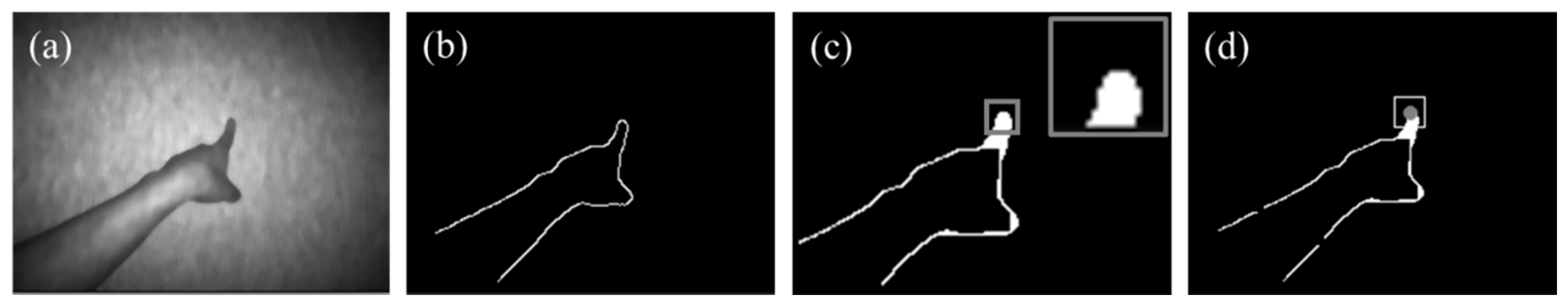
To enable interaction with the images superimposed on the flat surface, the system detects touch input when the user’s finger touches the surface. First, the system obtains an edge image (Figure 6b) from the infrared (IR) image (Figure 6a), which is captured by the depth camera, and fills inside a fingertip by applying closing to the edge image (Figure 6c). Then, the fingertip region is extracted by finding a white pixel by scanning the closing image from the upper left. Finally, the system detects a touch input when the difference between the average depth in the region inside the fingertip and that near the outside of the fingertip is lower than a threshold (Figure 6d).
4. Evaluation
By using the experimental system, we conducted an experiment to measure the registration accuracy and delay of the system. The purpose of this experiment was to measure the basic performance of our prototype, and did not include a usability test. We did not evaluate the performance of touch detection, since there has already been much research that focuses on touch detection using a depth camera [4,17,21]. Our research mainly focused on expanding the workspace rather than touch detection.
4.1. Registration Accuracy
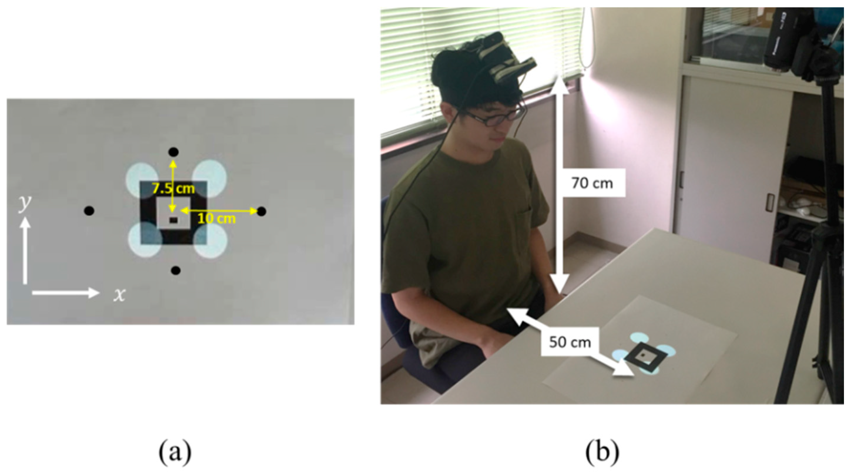
We measured how accurately the images were fixed when the head moved. In the experiment, one participant wearing the system on his head was seated in a chair, and the system projected circles onto the positions of the four vertices of an augmented reality (AR) marker [22], with a side of 8 cm, that was placed on a table. The participant moved his head to gaze at designated positions, and the system performed registration to fix the circles at the vertices of the AR marker.
One block was composed of the following four steps: (1) The participant moved his head from the center of the AR marker to each of the designated positions (left, right, top, and bottom), (2) stopped his head to gaze at the designated position, (3) moved his head back to the center, and (4) stopped his head to gaze at the center of the AR marker. Each step took 1 s, and each block took 4 s.
Figure 7a shows the designated points. The positions of points were 7.5 cm above and below the center of the marker, and 10 cm to the right and left of the marker. We determined the positions so that the marker was always within a projection image when the participant looked at any of the designated points. The participant performed four blocks continuously for all of the positions in the order of right, left, top and bottom.
We measured the 6-DOF errors between the AR marker and the projected circles. We performed a pose estimation of the AR marker and the projected circles, and estimated the transformation matrix between them. We calculated the 6-DOF movement errors, consisting of three translational DOF and three rotational DOF, from the transformation matrix. We used the ARToolKit [20] to estimate the poses of the AR marker and projected circles.
Figure 7b shows the overview of the experimental environment. The height of the system from the desk was 70 cm, and the distance between the participant and the AR marker was 50 cm. The translation from the rotation center of the head to the camera, and the positional relation between the projector and the camera were set manually before conducting the experiment.
The system ran at about 30 fps. To stabilize the projected image, the 1€ filter [23] was applied to the rotation angles that were calculated from the estimated plane. The 1€ filter is a first-order low-pass filter whose cutoff frequency is changed depending on the speed to minimize both jitter and the lag of signals.
Figure 8 and Figure 9 show the translation and rotation errors when the participant moved his head horizontally from the center to the right to see the right point, and then moved it back to the center.
Figure 10 and Figure 11 show the translation and rotation errors when the participant moved his head vertically from the center to the top to see the top point, and then moved it back to the center.
Table 1 shows the mean absolute error (MAE), root mean square error (RMSE), and standard deviation (SD) of the errors between the AR marker and the projected circles in all four blocks when the head was not moving. The maximum errors when his head was moving were 44.74 mm in x, 36.30 mm in y, 43.41 mm in z, 32.18 deg in ϕ (rotation around the x-axis), 21.35 deg in θ (rotation around the y-axis), and 4.77 deg in ψ (rotation around the z-axis).
As seen in Figure 8 and Figure 10, the registration errors in x became large when the head moved horizontally, and the errors in y became large when the head moved vertically. This is because the projected images were a little behind the head movement due to the delay of the system. When the head was not moving, the registration errors in x and y were about 10 mm, which did not bother the participant too much, but designers need to determine object sizes considering these errors. Our registration method used the normal to the detected plane, and the registration errors were affected by the errors in the plane detection. If the accuracy of plane detection is improved, the registration errors will be decreased.
4.2. Delay of the System
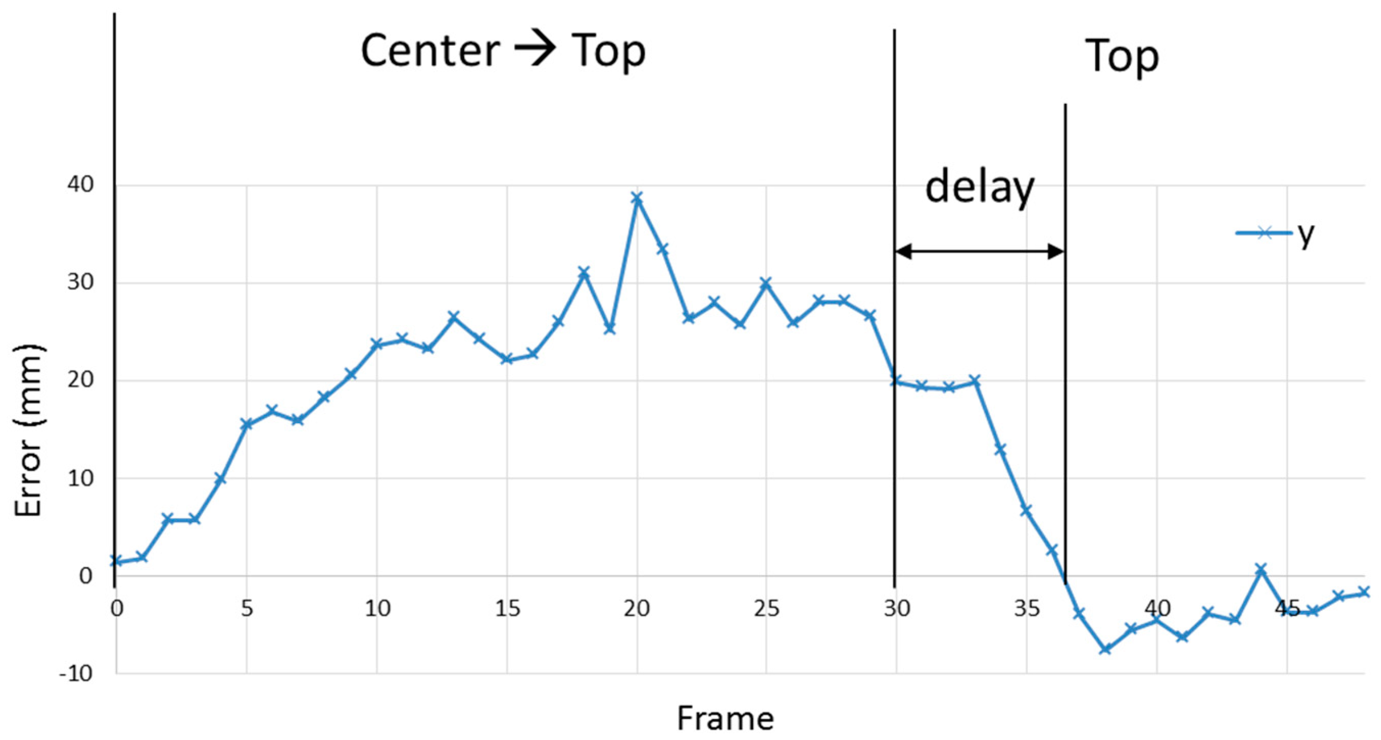
We measured the delay by averaging the times from when his head stopped (step 2) to when the projection circles went back to the vertices of the AR marker. We recorded a video around the marker from the position where both his head and the projection images were within the field-of-view of the video camera.
4.3. Limitation of the System
Based on the evaluation results above, we discuss the limitations of our experimental system.
4.3.1. DOF of Head Movement
Our experimental system performs pose estimation of the head using the normal to the detected plane for registration. This method can only obtain three DOF movements of the head, and cannot get the other three DOF (two translational and one rotational) movements. By using other sensors such as an IMU, the DOF will be increased, allowing a system that does not limit the head movement to be realized.
4.3.2. Delay
Our experimental system has a delay of about 0.2 s due to the delay of the projector and the depth camera. The use of a depth camera and a projector with shorter delay or delay compensation using other sensors will be effective for reducing the delay. Reduction of delay will also decrease the registration error and allow users to see more stable images.
4.3.3. Range of Image Projection
The projection angle of the projector used in the experimental system covers most of the central vision field, but does not cover the peripheral vision field. If the system can project wide images that cover the entire vision field, users will perceive more reality in a pseudo-large display. Nowadays, ultrashort focus projectors are being commercialized. If portable ones become available, a system that can project wider images will be realized.
4.3.4. Size
Our experimental system was still large and heavy, and it is hard to wear on the head. In the future, with the miniaturization of projectors and cameras, it should be possible to manufacture a more compact system such as an earphone-shaped one, which would reduce the disadvantages of wearing the system.
5. Conclusions
In this paper, we introduced a user interface that projects images on a flat surface, such as a table, by using a projector mounted on the user’s head and that realizes a large effective display area by changing the projected image according to the direction of the user’s head.
The system can superimpose an image on the flat surface by performing plane estimation, placing the image on the estimated plane, performing perspective projection to obtain a 2D image, and projecting the 2D image using the projector. Moreover, registration between the real world and the image was performed by estimating the user’s head pose using the estimated plane information. Furthermore, touch input was recognized by detecting the user’s finger on the plane using the depth camera.
As a result of measuring the positional deviation between the real world and the projected images using the experimental system, when the user stopped his head, translation errors were about 10 mm. In addition, we measured the delay of the system, and the result showed that the delay was estimated to be about 0.2 s.
The result of the evaluation revealed that there are many limitations in our experimental system. Among them, delay and weight are especially serious problems in practical use. For the commercialization of our proposed interface, these problems should be solved first. To reduce the delay of the entire system, delays of both the depth camera and the projector should be reduced. Instead of using a depth camera, a head-tracking camera like that used in Microsoft Hololens would also be effective. There are some commercial projectors that have short delay, but they are large. A small, lightweight, and fast projector is the key to realizing a more practical system.
In this paper, we just measured the basic performance of the system to clarify the limitations of the system. After overcoming these limitations, we will measure a more detailed performance with a number of participants, and also conduct usability tests involving a number of participants to verify the effectiveness of our proposed interface.
Author Contributions
Conceptualization, T.K.; Methodology, T.K.; Software, Y.K.; Validation, Y.K.; Writing—original draft, Y.K. and T.K.
Funding
This research received no external funding.
Conflicts of Interest
The authors declare no conflict of interest.
References
- Roeber, H.; Bacus, J.; Tomasi, C. Typing in thin air: The canesta projection keyboard—A new method of interaction with electronic devices. In Proceedings of the 21nd Human Factors in Computing Systems, New York, NY, USA, 5–10 April 2003; pp. 712–713. [Google Scholar]
- Wilson, A.D.; Benko, H. Combining multiple depth cameras and projectors for interactions on, above and between surfaces. In Proceedings of the 23rd annual ACM symposium on User Interface Software and Technology, New York, NY, USA, 3–6 October 2010; pp. 273–282. [Google Scholar]
- Wilson, A.; Benko, H.; Izadi, S.; Hilliges, O. Steerable augmented reality with the beamatron. In Proceedings of the 25th annual ACM symposium on User Interface Software and Technology, Cambridge, MA, USA, 7–10 October 2012; pp. 413–422. [Google Scholar]
- Harrison, C.; Benko, H.; Wilson, A.D. OmniTouch: Wearable multitouch interaction everywhere. In Proceedings of the 24th Annual ACM Symposium on User Interface Software and Technology, Santa Barbara, CA, USA, 16–19 October 2011; pp. 441–450. [Google Scholar]
- Dai, J.; Chung, C.-K.R. Touchscreen everywhere: On transferring a normal planar surface to a touch-sensitive display. IEEE Trans. Cybern. 2014, 44, 1383–1396. [Google Scholar] [CrossRef] [PubMed]
- Cao, X.; Balakrishnan, R. Interacting with dynamically defined information spaces using a handheld projector and a pen. In Proceedings of the 19th annual ACM symposium on User Interface Software and Technology, Montreux, Switzerland, 15–18 October 2006; pp. 225–234. [Google Scholar]
- Kaufmann, B.; Hitz, M. X-large virtual workspaces for projector phones through peephole interaction. In Proceedings of the 20th ACM International Conference on Multimedia, Nara, Japan, 29 October–2 November 2012; pp. 1279–1280. [Google Scholar]
- Fergason, J.L. Optical System for a Head Mounted Display Using a Retro-Reflector and Method of Displaying an Image. U.S. Patent 5,621,572, 24 August 1994. [Google Scholar]
- Inami, M.; Kawakami, N.; Sekiguchi, D.; Yanagida, Y.; Maeda, T.; Tachi, S. Visuo-haptic display using head-mounted projector. In Proceedings of the IEEE Virtual Reality 2000 Conference, New Brunswick, NJ, USA, 18–22 March 2000; pp. 233–240. [Google Scholar] [Green Version]
- Kijima, R.; Hirose, M. A compound virtual environment using the projective head mounted display. In Proceedings of the International Conference on Virtual Reality Software and Technology 1995, Chiba, Japan, 20–22 November 1995; pp. 111–121. [Google Scholar]
- Bolas, M.; Krum, D.M. Augmented reality applications and user interfaces using head-coupled near-axis personal projectors with novel retroreflective props and surfaces. In Proceedings of the Pervasive 2010 Ubiprojection Workshop, Helsinki, Finland, 17 May 2010. [Google Scholar]
- Kade, D.; Akşit, K.; Ürey, H.; Özcan, O. Head-mounted mixed reality projection display for games production and entertainment. Pers. Ubiquitous Comput. 2015, 19, 509–521. [Google Scholar] [CrossRef]
- Yoshida, T.; Kuroki, S.; Nii, H.; Kawakami, N.; Tachi, S. ARScope. In Proceedings of the 35th International Conference on Computer Graphics and Interactive Techniques, Westmont, IL, USA, 12–14 August 2008. [Google Scholar]
- Mistry, P.; Maes, P.; Chang, L. WUW-wear Ur world: A wearable gestural interface. In Proceedings of the Extended Abstracts on Human Factors in Computing Systems, Boston, MA, USA, 4–9 April 2009; pp. 4111–4116. [Google Scholar]
- Tamaki, E.; Miyaki, T.; Rekimoto, J. Brainy hand: An ear-worn hand gesture interaction device. In Proceedings of the Extended Abstracts on Human Factors in Computing Systems, Boston, MA, USA, 4–9 April 2009; pp. 4255–4260. [Google Scholar]
- Kemmoku, Y.; Komuro, T. AR Tabletop Interface using a Head-Mounted Projector. In Proceedings of the 15th IEEE International Symposium on Mixed and Augmented Reality, Merida, Mexico, 19–23 September 2016; pp. 288–291. [Google Scholar]
- Xiao, R.; Schwarz, J.; Throm, N.; Wilson, A.D.; Benko, H. MRTouch: Adding Touch Input to Head-Mounted Mixed Reality. IEEE Trans. Vis. Comput. Gr. 2018, 24, 1653–1660. [Google Scholar] [CrossRef] [PubMed]
- Besl, P.J.; McKay, N.D. A method for registration of 3-D shapes. IEEE Trans. Pattern Anal. Mach. Intell. 1992, 14, 586–606. [Google Scholar] [CrossRef]
- Klein, G.; Murray, D. Parallel tracking and mapping for small AR workspaces. In Proceedings of the IEEE and ACM International Symposium on Mixed and Augmented Reality, Washington, DC, USA, 13–16 November 2007; pp. 225–234. [Google Scholar]
- Fischler, M.A.; Bolles, R.C. Random sample consensus: A paradigm for model fitting with applications to image analysis and automated cartography. Commun. ACM 1981, 24, 381–395. [Google Scholar] [CrossRef]
- Wilson, A.D. Using a depth camera as a touch sensor. In Proceedings of the ACM International Conference on Interactive Tabletops and Surfaces, Saarbrücken, Germany, 7–10 November 2010; pp. 69–72. [Google Scholar]
- ARToolKit. Available online: http://artoolkit.sourceforge.net/ (accessed on 16 September 2018).
- Casiez, G.; Roussel, N.; Vogel, D. 1€ filter: A simple speed-based low-pass filter for noisy input in interactive systems. In Proceedings of the SIGCHI Conference on Human Factors in Computing Systems, Austin, TX, USA, 5–10 May 2012; pp. 2527–2530. [Google Scholar]
Figure 1.
Concept of the proposed system. By using the head-mounted projector, images are always projected in front of the user in the direction of the user’s gaze. The image to be projected is changed according to the user’s head pose so as to fix the superimposed images on the surface.
Figure 1.
Concept of the proposed system. By using the head-mounted projector, images are always projected in front of the user in the direction of the user’s gaze. The image to be projected is changed according to the user’s head pose so as to fix the superimposed images on the surface.

Figure 2.
Experimental system. A mobile projector that a depth camera is attached to is worn on the user’s head.
Figure 2.
Experimental system. A mobile projector that a depth camera is attached to is worn on the user’s head.

Figure 3.
Superimposing an image on a flat surface. The image looks to have the proper size and shape on a flat surface.
Figure 3.
Superimposing an image on a flat surface. The image looks to have the proper size and shape on a flat surface.

Figure 4.
Object movement by the rotation of the head. The camera undergoes translation when the head is rotated, because the rotation center of the head does not correspond to the center of the camera.
Figure 4.
Object movement by the rotation of the head. The camera undergoes translation when the head is rotated, because the rotation center of the head does not correspond to the center of the camera.
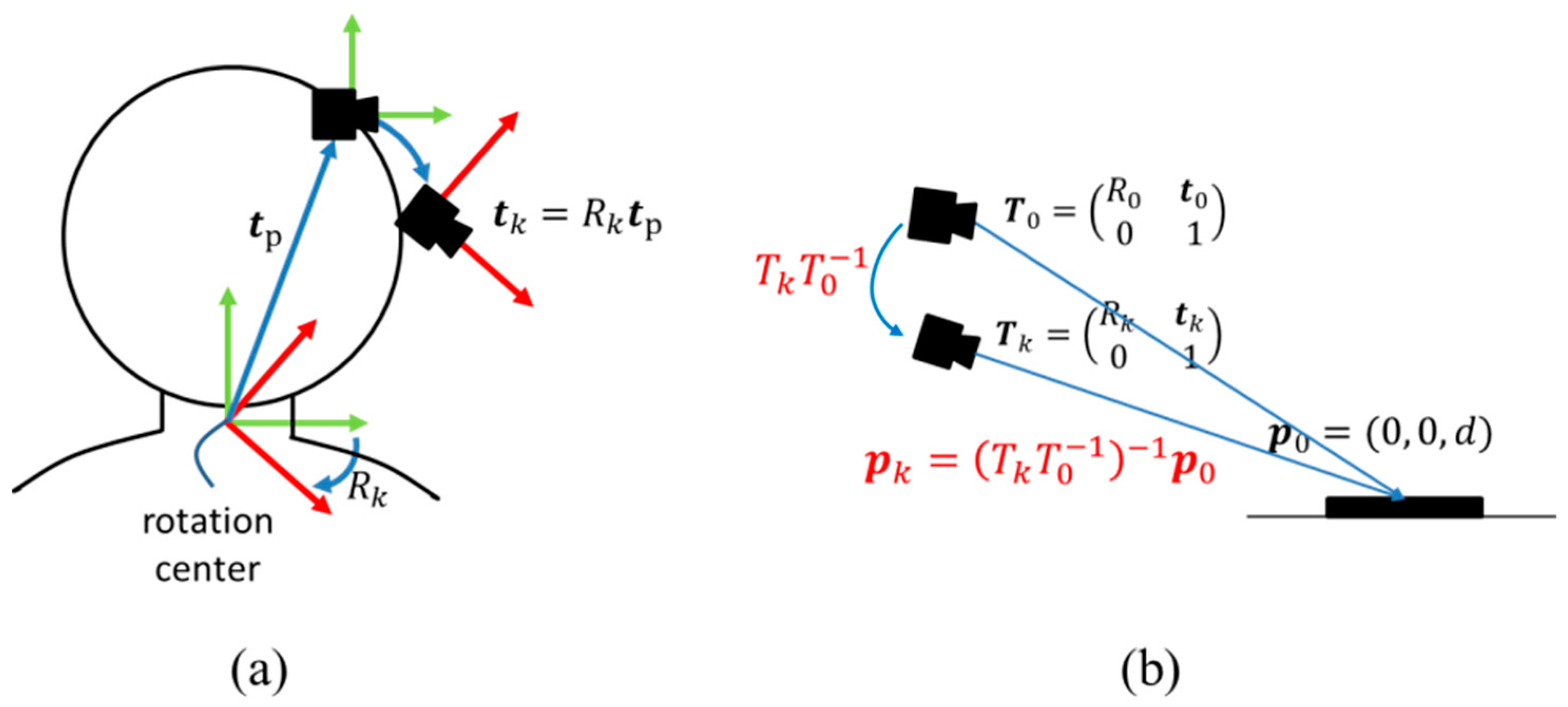
Figure 5.
Images displayed when the user’s head moved, taken from behind the head. The images are always in the direction of the user’s gaze, and the virtual information space is fixed on the surface.
Figure 5.
Images displayed when the user’s head moved, taken from behind the head. The images are always in the direction of the user’s gaze, and the virtual information space is fixed on the surface.
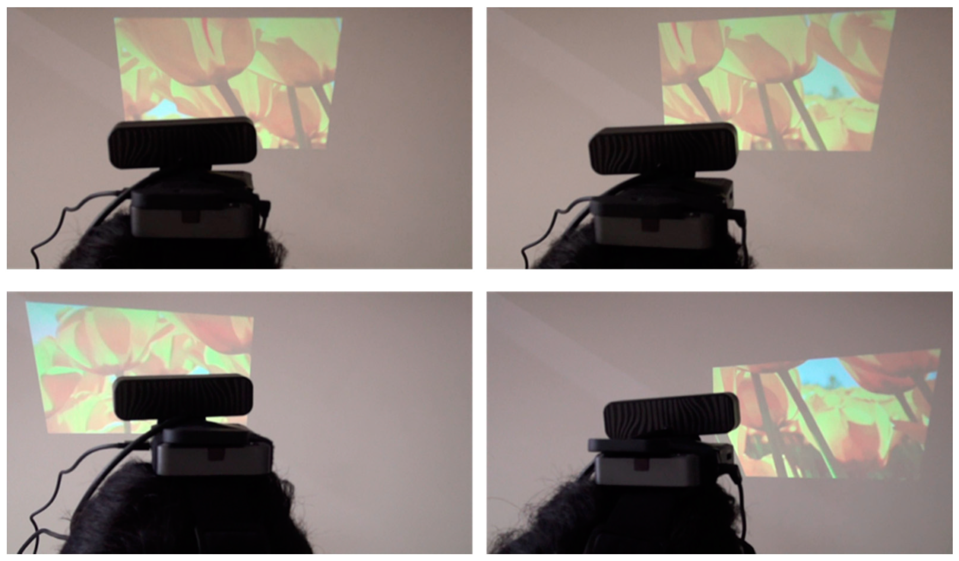
Figure 6.
Touch detection method. It uses the IR image captured by the depth camera to extract the fingertip region.
Figure 6.
Touch detection method. It uses the IR image captured by the depth camera to extract the fingertip region.

Figure 7.
Experimental setup for evaluating registration accuracy. Six degrees-of-freedom (6-DOF) errors between the AR marker and the projected circles are measured.
Figure 7.
Experimental setup for evaluating registration accuracy. Six degrees-of-freedom (6-DOF) errors between the AR marker and the projected circles are measured.

Figure 8.
Translation errors when the head moved horizontally.

Figure 9.
Rotation errors when the head moved horizontally.

Figure 10.
Translation errors when the head was moved vertically.

Figure 11.
Rotation errors when the head was moved vertically.
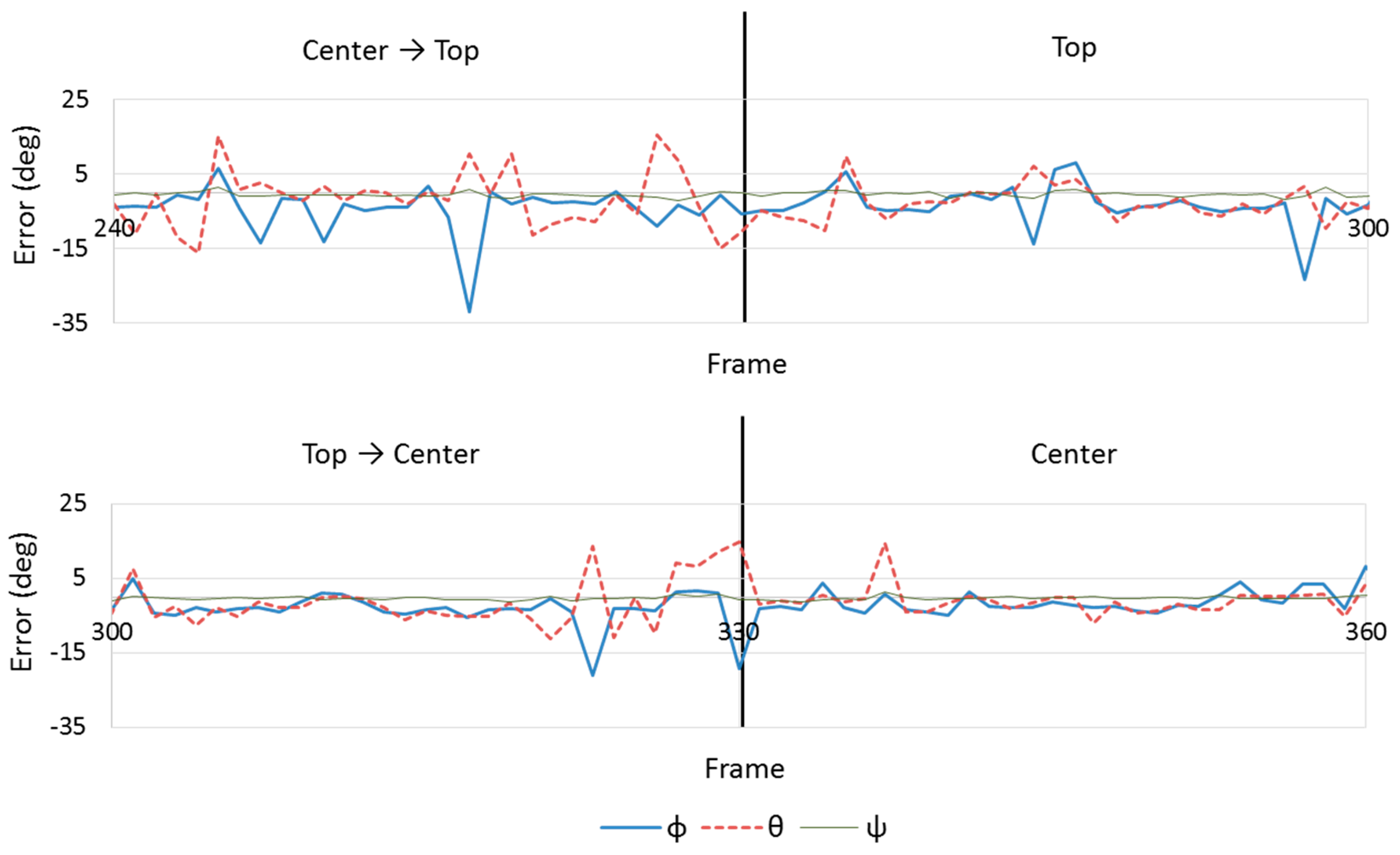
Figure 12.
A sequence of photographs around the marker from when the participant stopped his head after moving his head from the center to the top.
Figure 12.
A sequence of photographs around the marker from when the participant stopped his head after moving his head from the center to the top.

Figure 13.
Translation errors in y when the participant stopped his head after moving his head from the center to the top.
Figure 13.
Translation errors in y when the participant stopped his head after moving his head from the center to the top.


Table 1.
Measured errors when the head was not moving. MAE: mean absolute error, RMSE: root mean square error, SD: standard deviation.
Table 1.
Measured errors when the head was not moving. MAE: mean absolute error, RMSE: root mean square error, SD: standard deviation.
| x [mm] | y [mm] | z [mm] | [deg] | [deg] | [deg] | |
|---|---|---|---|---|---|---|
| MAE | 10.20 | 7.20 | 14.28 | 4.02 | 4.69 | 1.01 |
| RMSE | 14.64 | 9.75 | 17.70 | 5.42 | 6.74 | 1.39 |
| SD | 12.96 | 9.45 | 15.54 | 5.09 | 6.72 | 1.39 |
© 2018 by the authors. Licensee MDPI, Basel, Switzerland. This article is an open access article distributed under the terms and conditions of the Creative Commons Attribution (CC BY) license (http://creativecommons.org/licenses/by/4.0/).
Share and Cite
MDPI and ACS Style
Kemmoku, Y.; Komuro, T. A Large Effective Touchscreen Using a Head-Mounted Projector. Information 2018, 9, 235. https://doi.org/10.3390/info9090235
AMA Style
Kemmoku Y, Komuro T. A Large Effective Touchscreen Using a Head-Mounted Projector. Information. 2018; 9(9):235. https://doi.org/10.3390/info9090235
Chicago/Turabian StyleKemmoku, Yusuke, and Takashi Komuro. 2018. "A Large Effective Touchscreen Using a Head-Mounted Projector" Information 9, no. 9: 235. https://doi.org/10.3390/info9090235
Note that from the first issue of 2016, this journal uses article numbers instead of page numbers. See further details here.