Article

Quantization-Based Image Watermarking by Using a Normalization Scheme in the Wavelet Domain

1
School of Information and Communication Engineering, University of Electronic Science and Technology of China, Chengdu 611731, China
2
School of Mathematics and Computer Science, ShangRao Normal University, Shangrao 334001, China
3
School of Physics and Electronic Information, ShangRao Normal University, Shangrao 334001, China
*
Author to whom correspondence should be addressed.
Information 2018, 9(8), 194; https://doi.org/10.3390/info9080194
Submission received: 10 July 2018 / Revised: 23 July 2018 / Accepted: 26 July 2018 / Published: 30 July 2018
(This article belongs to the Section Information Processes)

Abstract

:
To improve the invisibility and robustness of quantization-based image watermarking algorithms, we developed an improved quantization image watermarking method based on the wavelet transform and normalization strategy used in this study. In the process of watermark encoding, the sorting strategy of wavelet coefficients is used to calculate the quantization step size. Its robustness lies in the normalization-based watermark embedding and the control of its amount of modification on each wavelet coefficient by utilizing the proper quantization parameter in a high entropy image region. In watermark detection, the original unmarked image is not required, and the probability of false alarms and the probability of detection are discussed through experimental simulation. Experimental results show the effectiveness of the proposed watermarking. Furthermore, the proposed method has stronger robustness than the alternative quantization-based watermarking algorithm.

1. Introduction

With the rapid development of information technologies, multimedia data, such as images and video, can be accessed and distributed in a variety of ways. However, the widespread use of the multimedia file has brought problems regarding the preservation of copyright. Therefore, protecting the copyright of multimedia data has been a challenging problem. As one of the effective copyright protection technologies, digital image watermarking has been widely studied [1,2,3,4,5,6]. The main idea of image watermarking is to embed imperceptible information into the host image and verify the owner of the copyright by detecting the embedded information.
In general, an image watermarking method should at least meet two requirements. One is imperceptibility and the other is robustness. However, it is a difficult task to develop a watermarking method that satisfies the two requirements. As we all know, the imperceptibility and the robustness of watermarking are in conflict with each other. Specifically, on the one hand, image distortion should be reduced as much as possible during watermark embedding. On the other hand, it should enhance watermark embedding strength for improving the robustness of watermarking, and thus may be seriously affect the image quality. As a consequence, the design of a watermarking algorithm always includes the tradeoff of these two requirements and it should improve the robustness as possible without seriously affecting the host image.
Inspired by the idea of communication and coding, most watermarking algorithms have been presented in recent years. For instance, based on principles of spread spectrum communication, researchers have proposed a number of watermarking methods [7,8]. The spread spectrum-based watermarking is simple and efficient. However, the signal-to-noise ratio is very small when host interference exists. To address this problem, some quantization based watermarking methods that are based on visual models have been studied [9,10].
Kundur and Hatzinakos [9] proposed a quantization watermarking method based on wavelet transform. Their method implements quantitative embedding by modifying the amplitude relationship of three sets of wavelet coefficients. Their proposed watermarking is robust to a variety of image distortions, such as JPEG compression, noise, and image filtering, etc. To improve the invisibility of watermarks while satisfying the robustness requirement, Liang-Hua and Jyh-Jiun [10] proposed a watermarking method based on the mean quantization scheme by taking into account the human visual system. Experimental results show that both the imperceptibility and robustness of watermarking are well satisfied through simulation. Besides, according to the human visual model [11], the maximum quantization interval should be bounded in the procedure of watermarking embedding; thus the image visual quality can be maintained.
In addition, the literature [12] presents the Quantization Index Modulation (QIM)-based watermarking method. This method has good rate distortion-robustness tradeoffs. Although the QIM-based watermarking is simple and easy to implement, the watermarking method is sensitive to amplitude scaling attack; even small changes in signal amplitude can lead to a sharp increase in BER (Bit error ratio). In order to address this issue, several watermarking methods have been proposed. By applying a gain-invariant adaptive quantization step-size, Gonzalez et al [13] designed a RDM (rational dither modulation, RDM)-based watermarking algorithm. The watermarking algorithm is robust against amplitude scaling attack, but the complexity of the algorithm is high. Jiao Li and Cox proposed an adaptive quantization index modulation (AQIM) watermarking [14] based on the modified Watson visual perceptual model. The algorithm can select quantization step size adaptively based on the Watson visual perception model. The main advantage of their method has been its invariance towards amplitude scaling.
N.K.Kalantari et.al. [15] presents a logarithmic QIM (LQIM) watermarking method. The advantages of the proposed method [15] are desirable from a perceptual perspective, and by adopting this point of view, the small quantization step is devoted to the smaller amplitude, and the larger quantization step is related to the larger amplitude. However, the proposed method [15] does not take into account the visual perception model of the image itself, which may introduce some perceptible distortions when decoding the watermark data. Furthermore, a gain invariant quantization-based image watermarking method has been proposed in [16], which is robust towards gain attack. Because the division function is used, the decoding of the watermark is not affected. As a result, their watermarking algorithm is invariant to gain attack. Moreover, other quantization-based watermarking methods [17,18] have been proposed; details can be referred to [17,18].
It can be seen that these quantization-based methods have the potential to be used for designing the robust image watermarking. However, theoretical analysis and experimental results show that these quantization-based algorithms are not mature in the wavelet domain. The following problems are summarized. Firstly, the watermarked image may be sensitive to malicious attack, thus resulting in the modified wavelet coefficient being moved to another position. The second problem is that little consideration has been given to the geometric invariant processing based on the properties of original image for quantization watermarking, thus resulting in the proposed watermarking method having poor robustness against geometric attacks, such as rotation, amplitude scaling and cropping.
In this paper, we developed an image watermarking algorithm by using a normalized scheme and the quantization strategy. First, the image was normalized to achieve invariance under affine geometric distortions based on [19]. Then the quantization parameter estimate was chosen from a collection of candidate parameters. The estimate is selected to be the maximum robustness of the watermarking method.
The contributions of this proposed watermarking method are summarized as follows. First, the quantization step size was calculated by the wavelet coefficient sorting scheme, and the amount of modification on each wavelet coefficient was controlled with the proper quantization parameter, thus the distortion of the image can be reduced during watermark embedding. Second, the selected blocks have high entropy and texture complexity. Therefore, we can embed strong watermark data into the complex texture region of image. Third, due to the normalization scheme, the proposed quantization watermarking can be robust against some geometric attacks.
The rest of paper is structured as follows. Some related works are presented in Section 2; Section 3 presents the proposed watermarking method, and Section 4 gives the experimental results. Lastly, we conclude this paper in Section 5.

2. Related Work

2.1. Image Normalization

The original image was normalized to achieve invariance under affine geometric distortions by applying moments [19]. First, the normalization technique was used to preprocess the original image, thus the watermark data sequences were embedded into the normalized image in the second phase. The application of the normalization scheme was to successfully extract the watermark information whereas the watermarked image was translated, scaled and rotated, which enhanced the robustness of the watermarking. For a given image I ( x , y ) of size M × N , the main normalization procedure [19] contains the following processes:
Step 1: Center the original image I ( x , y ) ; this is achieved by the Equation (2), Let I 1 ( x , y ) denote the resulting centered image, I 1 ( x , y ) = I ( x 1 , y 1 ) , where A = ( 1 , 0 0 , 1 ) and d = ( d 1 d 2 ) , d 1 = m 10 / m 00 , d 2 = m 01 / m 00 . Where m 10 , m 01 , m 00 are the moments of I ( x , y ) , the definitions were expressed as follows by Equation (1):
m 10 = x = 0 M 1 y = 0 N 1 x I ( x , y ) , m 01 = x = 0 M 1 y = 0 N 1 y I ( x , y )  
( x 1 y 1 ) = A ( x y ) d  
Step 2: In the x direction, utilize a shearing transform to I 1 ( x , y ) by using matrix A x = ( 1 , β 0 , 1 ) , which results in the sheared image denoted by I 2 ( x , y ) = A x [ I 1 ( x , y ) ] . Similar to this operation, in the y direction, utilize a shearing transform to I 2 ( x , y ) by applying matrix A y = ( 1 , 0 γ , 1 ) , which results in the sheared image denoted by I 3 ( x , y ) = A y [ I 2 ( x , y ) ] . Finally, Scale I 3 ( x , y ) in both x and the y directions by using the scaling matrix A s = ( α , 0 0 , δ ) denoted by I ¯ ( x , y ) = A s [ I 3 ( x , y ) ] , the I ¯ ( x , y ) represents the normalized image. The setting of parameters β , γ , α , δ can be referred to literature [19].

2.2. The Wavelet Transform

Wavelet transform is an effective multi-resolution analysis method, which has been widely applied in image processing, image compression, computer vision and other fields. Figure 1 shows the procedure of wavelet decomposition with one scale on the Lena image.
As can be seen in Figure 1, after decomposing the Lena image by using the wavelet transform, a series of sub-band images with different resolutions can be obtained. In Figure 1, the top left part represents the low-frequency sub-band image, the upper right part is the horizontal direction sub-band image; the bottom left part represents the vertical direction sub-band image and the bottom right part represents diagonal sub-band image. Generally speaking, in the direction of every row of the matrix, an image is firstly decomposed by one-scale wavelet transform, obtaining the low frequency component and high frequency component horizontally. Second, in the direction of every column of the matrix, obtained components are decomposed by one-scale wavelet transform. When the image is firstly decomposed by one-scale wavelet transform, similarly by taking the low-frequency sub-band image as the decomposed image, the second-scale wavelet transform can be performed in the same manner as the first processes of wavelet decomposition. Accordingly, the Low-frequency sub-band image, horizontal direction sub-band image, vertical direction sub-band image and the diagonal sub-band image of second-scale are also obtained. Multi-scale wavelet decomposition repeats the above process.

3. Proposed Watermarking Method

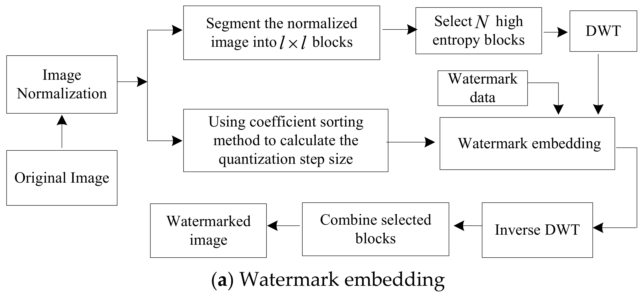
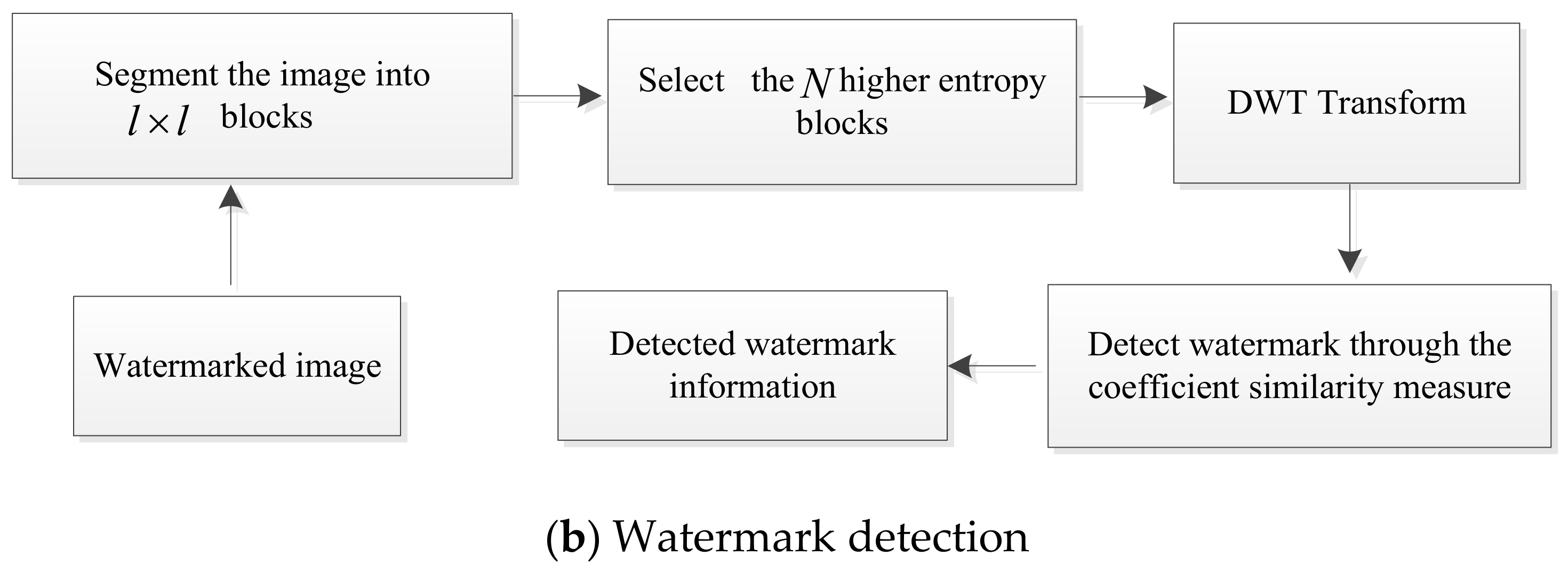
According to studies on human visual perception system [10], we propose an image watermarking method by using normalization scheme in this study. Figure 2 shows the flow chart of the proposed watermarking method, which includes watermark embedding and watermark detection. The main advantage of this watermarking method is that it is simple to implement; and the trade-off between imperceptibility and robustness has been elegantly achieved through a proper quantization step size-based embedding in the high image entropy regions. On the other hand, the normalization strategy is utilized to design the watermarking algorithm in the wavelet domain, which can improve the robustness of watermarking when against some common attacks, such as JPEG compression, rotation, amplitude scaling and combinational attack.

3.1. Watermark Embedding

During watermark embedding, the watermark data was assumed to be binary information, which includes elements of the set {−1, 1}. For the security of the watermark, the watermark data was embedded into the host image by using a key. The key consists of two parts: One is the length of watermark N and the second is the quantization parameter Q . Inspired by [20], we embed the watermark in the high entropy region using the discrete wavelet transform (DWT) and detect the watermark data without the host image. As shown in Figure 2a, the steps of watermark embedding were described as follows.
Step 1: The normalized image I ¯ ( x , y ) was segment into l × l non-overlapping blocks and N high entropy image blocks were chosen.
Step 2: Each selected block was decomposed by applying the wavelet transform. For each block image, the following steps are carrying out.
Step 3: Three detail sub-band images of each block image was obtained, which consists of the horizontal, vertical and diagonal sub-band image, respectively. The three sub-band images denoted by I s H = { I s H ( i , j ) } , I s V = { I s V ( i , j ) } , I s D = { I s D ( i , j ) } and coefficient location ( i , j ) , respectively, where s denotes the decomposition scale. Then sort the high-frequency sub-band wavelet coefficients so that I s h ( i , j ) , I s v ( i , j ) , and I s d ( i , j ) were coefficients such that I s k 1 ( i , j ) I s k 2 ( i , j ) I s k 3 ( i , j ) , where k 1 , k 2 , k 3 { h , v , d } .
Step 4. The range of values between I s k 1 ( i , j ) and I s k 3 ( i , j ) was divided into bits of width as follows:
Δ = I s k 3 ( i , j ) I s k 1 ( i , j ) 2 Q 1  
where Q is the quantization parameter in which to control the quantization step size. The range of quantization parameter is from 0.8 to 8. Δ represents the quantization step size. Then a single bit of “−1” or “1” was embedded into each block by modifying the middle wavelet coefficients in the high-frequency sub-bands:
{ I s k 2 ( i , j ) = I s k 1 ( i , j ) + n Δ , i f ( n mod 2 ) = = 0 I s k 2 ( i , j ) = I s k 1 ( i , j ) + ( n + 1 ) Δ , i f ( n mod 2 ) 0 , F o r   e m b e d d i n g 1
{ I s k 2 ( i , j ) = I s k 1 ( i , j ) + ( n + 1 ) Δ , i f ( n mod 2 ) = = 0 I s k 2 ( i , j ) = I s k 1 ( i , j ) + n Δ ,           i f ( n mod 2 ) 0 , F o r   e m b e d d i n g   1
where n = f i x ( ( I s k 2 ( i , j ) I s k 1 ( i , j ) ) / Δ ) , the function f i x ( ) represents integer rounding function.
Step 5: The modified coefficients were reconstructed by the inverse wavelet transform, which obtain the watermarked image.
Step 6: Finally, the watermarked image blocks were combined with the non-watermarked image blocks, which provides the whole watermarked image.

3.2. Watermark Detection

The objective of the watermark detection is to obtain the watermark data estimate of the host watermark from the distorted watermarked image. The watermark data extraction needs the same key as the watermark embedding. In this work, the watermarked image was represented by I ^ . We extracted the watermark data as the following way as shown in Figure 2b.
Step 1: The watermarked image I ^ was partitioned into l × l non-overlapping blocks and high entropy image blocks were chosen.
Step 2: The selected image blocks were decomposed by applying the wavelet transform. For each block image, the following steps are carrying out.
Step 3: Three detail sub-band images of each block image were chosen, which consist of the horizontal, vertical and diagonal sub-band image, respectively. The three sub-band images denoted by I ^ s H = { I ^ s H ( i , j ) } , I ^ s V = { I ^ s V ( i , j ) } , I ^ s D = { I ^ s D ( i , j ) } and coefficient location ( i , j ) , respectively, where s denotes the decomposition scale. Then the detail coefficients were sorted so that I ^ s h ( i , j ) , I ^ s v ( i , j ) , and I ^ s d ( i , j ) were coefficients such that I ^ s k 1 ( i , j ) I ^ s k 2 ( i , j ) I ^ s k 3 ( i , j ) , where k 1 , k 2 , k 3 { h , v , d } .
Step 4: The range of values between I ^ s k 1 ( i , j ) and I ^ s k 3 ( i , j ) was divided into bits of width as follows:
Δ = I ^ s k 3 ( i , j ) I ^ s k 1 ( i , j ) 2 Q 1  
where Q is a parameter that is the same as watermark embedding. Then we extract the watermark information in each block based on the following strategy:
{ i f   ( n mod 2 ) = 0 , w h e n   D 1 < D 2 , i f   ( n mod 2 ) 0 , w h e n   D 1 > D 2 , F o r   e x t r a c t i n g 1
{ i f   ( n mod 2 ) = 0 , w h e n   D 1 > D 2 , i f   ( n mod 2 ) 0 , w h e n   D 1 < D 2 , F o r   e x t r a c t i n g   1
where D 1 = I ^ s k 2 ( i , j ) ( I ^ s k 1 ( i , j ) + n Δ ) ; D 2 = ( I ^ s k 1 ( i , j ) + ( n + 1 ) Δ ) I ^ s k 2 ( i , j ) , and n is the same as Equations (4) and (5).
Step 5: The normalized correction (NC) coefficient between the original watermark and the extracted watermark was calculated to judge whether the watermark data has been embedded in the watermarked image.
ρ ( w , w ^ ) = i = 1 , j = 1 N w w ( i , j ) w ^ ( i , j ) i = 1 , j = 1 N w w 2 ( i , j ) i = 1 , j = 1 N w w ^ 2 ( i , j ) , i , j = 1 , 2 , . N w  
If ρ ( w , w ^ ) > T thus the watermark was detected, T is a pre-defined detection threshold value.
In order to determine the watermark detection threshold T , the Neyman–Pearson criterion [21] was utilized in this work. From [21], the detection threshold T can be formulated as T = [ Q 1 ( P f / 2 ) ] 2 . Where P f denotes the probability of a false positive and Q ( ) represents the right-tail probabilities of the Gaussian distribution, and the Q ( ) -function and its relationship to the complementally error function e r f c ( ) is given by Q ( x ) = 1 2 e r f c ( x 2 ) . In practice, P f is set to 10 6 . Due to the computation of detection threshold using the Neyman–Pearson criterion on the watermarked image, the extraction of watermark data does not require the host image.

4. Experimental Results and Analysis

In this work, several experiments were performed to evaluate the proposed watermarking method, which consists of imperceptibility and robustness test. During the process of experiments, the image covers Fingerprint, Lena, Barbara, Crowd, Mandrill, Boat, Mit and Bridge. The size of these images is 512 × 512 and the size of each block is 16 × 16, thus the total number of image blocks is 1024. The discrete wavelet transform with three scales of decomposition was utilized to transform each block image. The watermark data was embedded in the wavelet coefficients of the third scales of image, thus the number of coefficients utilized to encode the watermark data is 4096. The biorthogonal CDF 9/7 wavelet filter was selected. Experimental parameter settings are provided in Table 1.
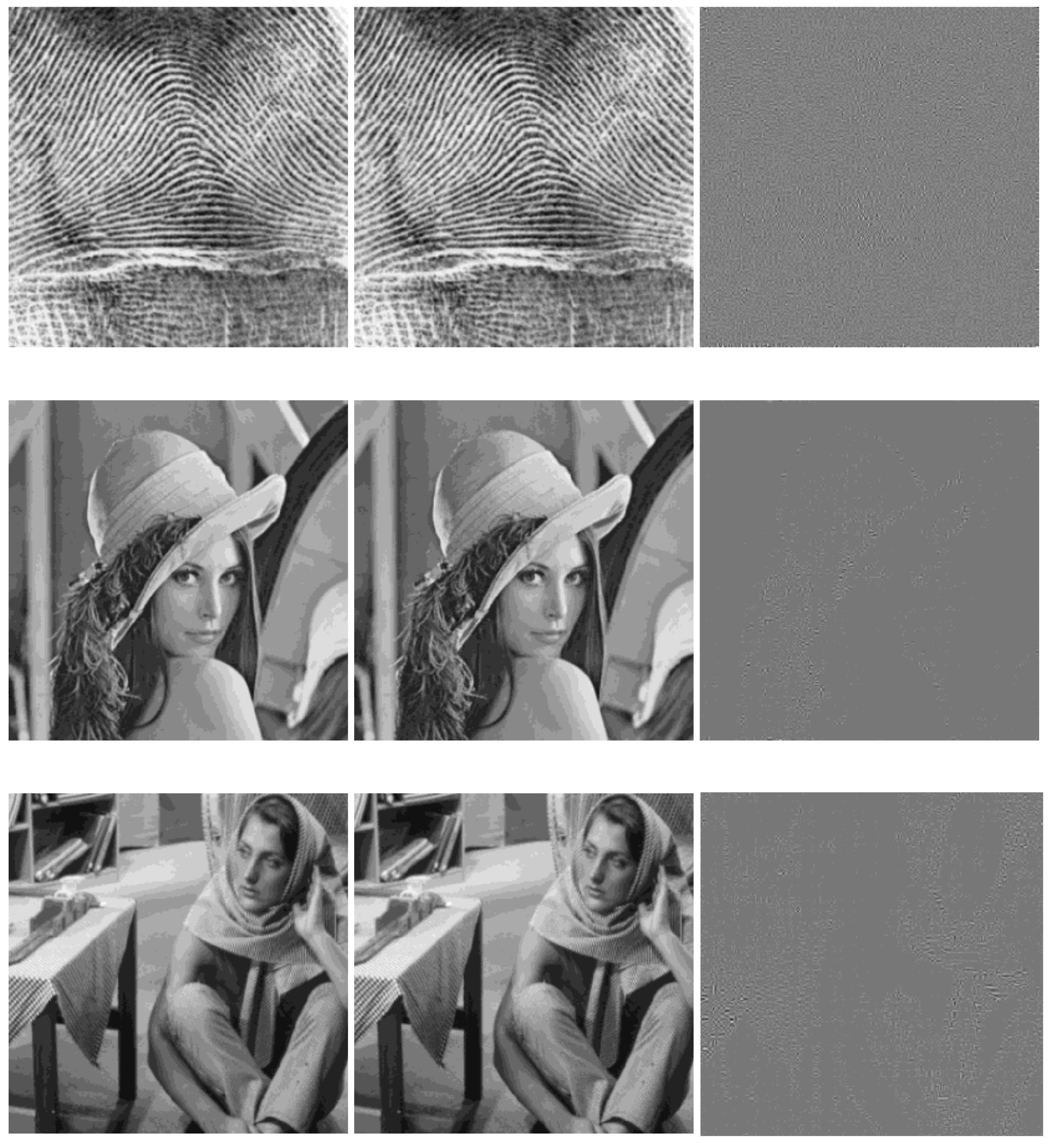
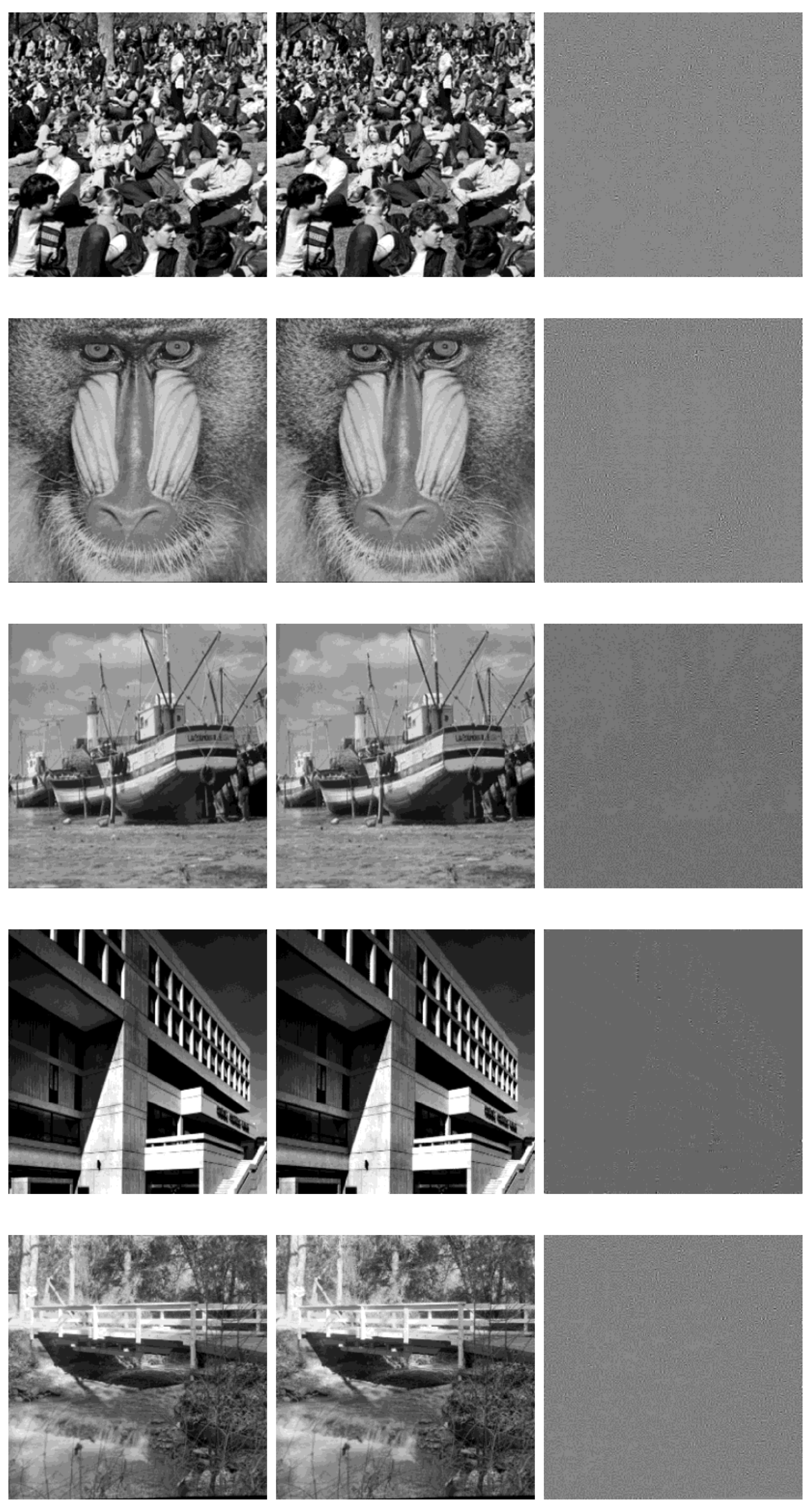
Figure 3 shows the invisibility results for all images. It can be seen that the effectiveness of the proposed method and the imperceptibility is also satisfied from Figure 3. The difference between the host image and watermarked image is small. We can see that the watermark data was embedded along the high texture area.
Besides, we show the computational time of the proposed watermarking method with different image in Table 2. Note that all the results are implemented in MATLAB R2016a. As shown in Table 2, the proposed watermarking algorithm has high computational efficiency.

4.1. Robustness Test

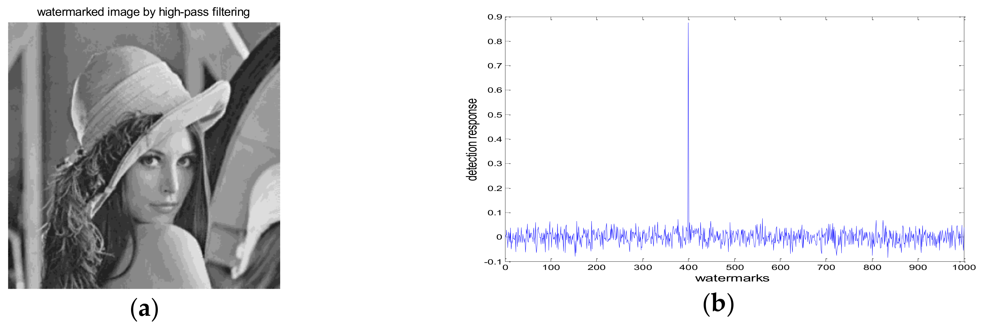
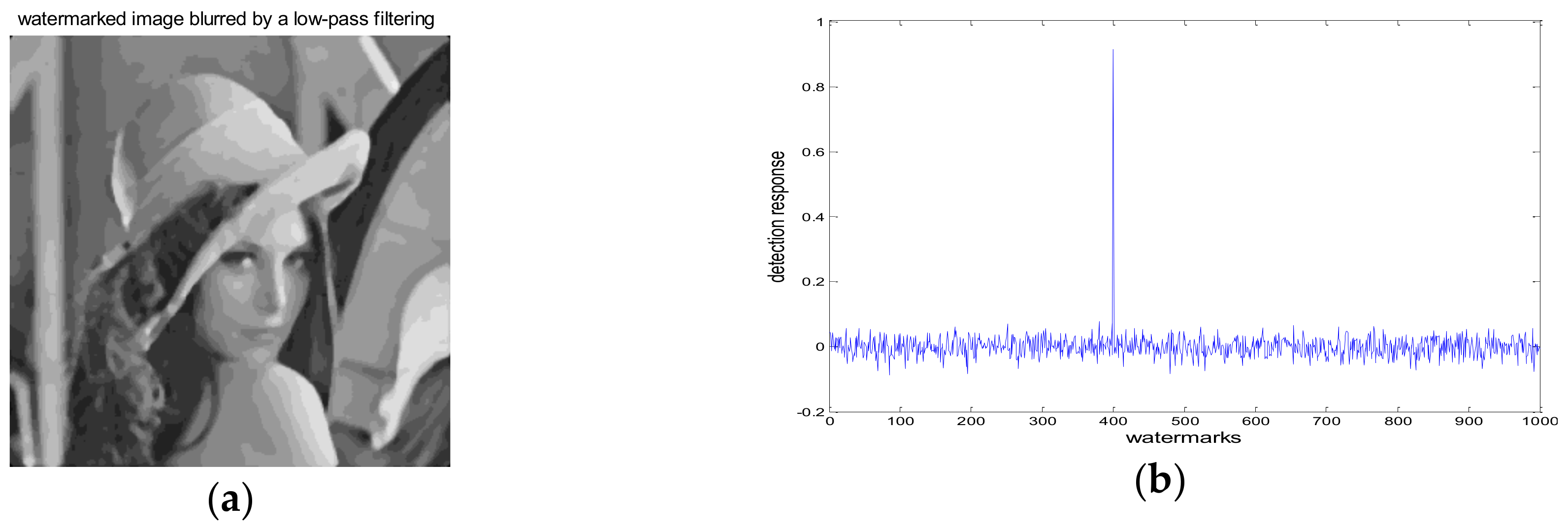
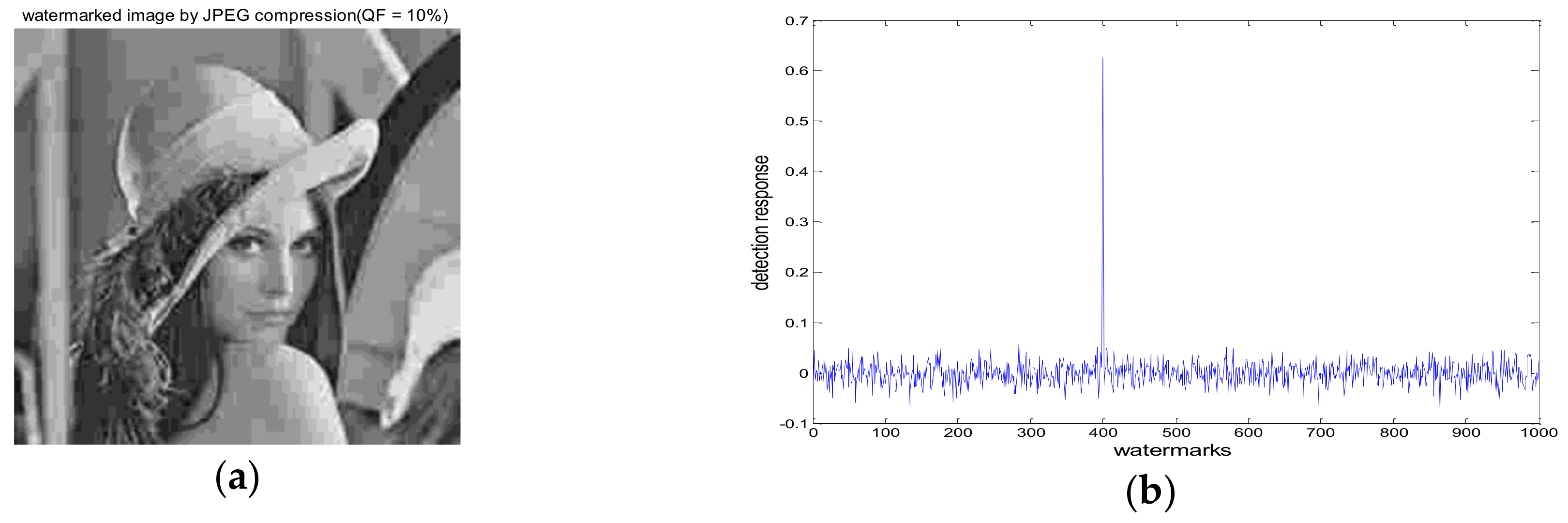
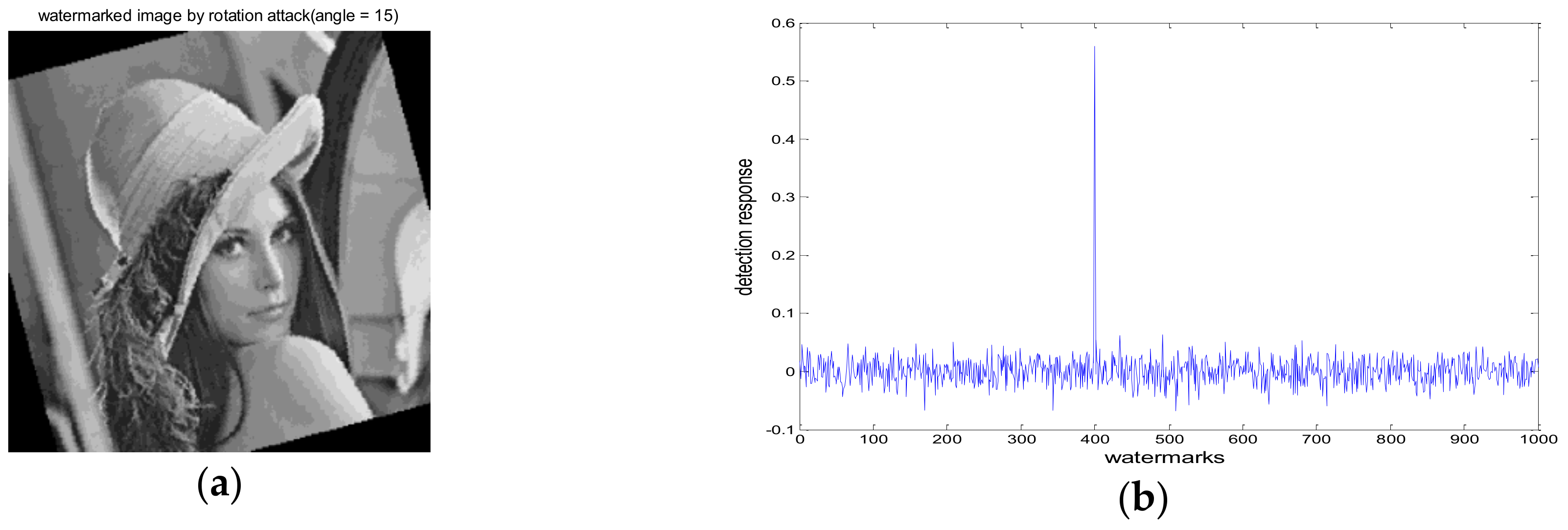
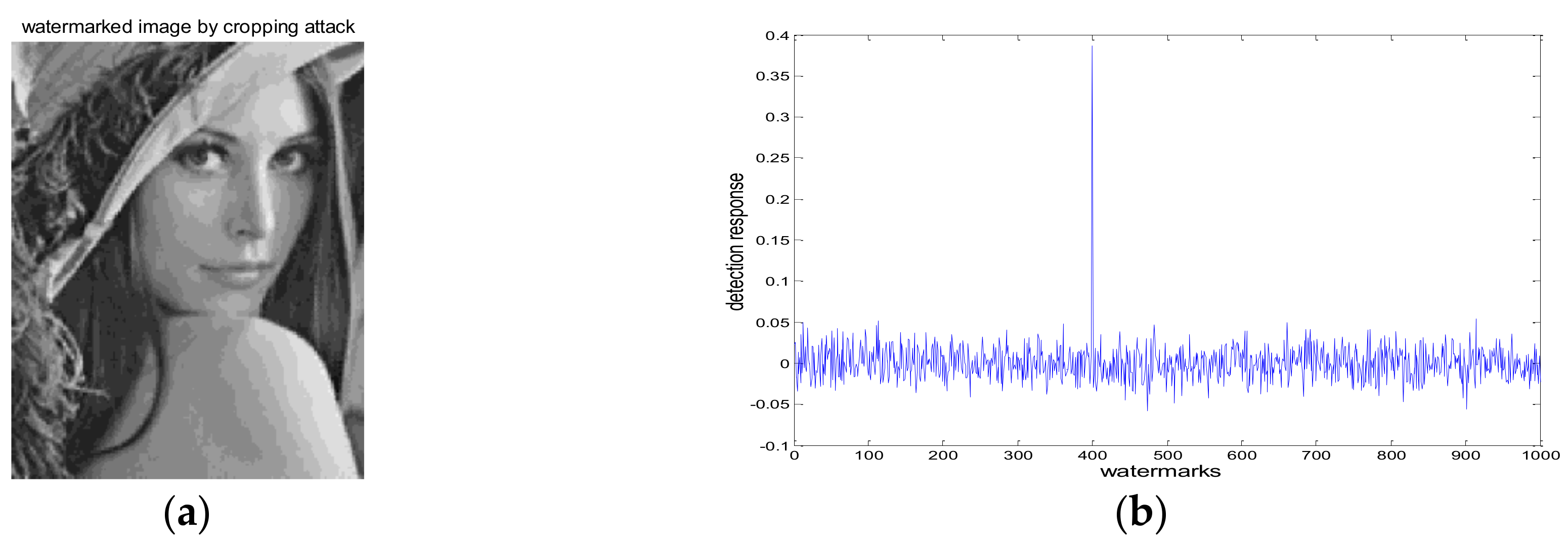
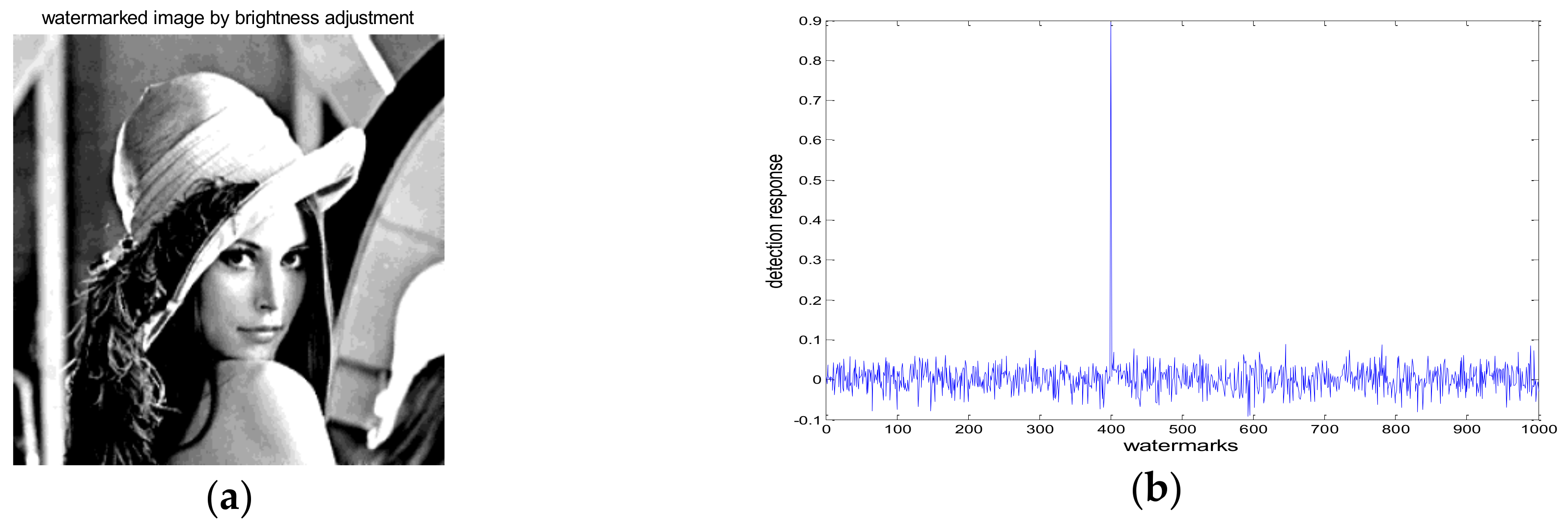
Apart from the imperceptibility test, the robustness test includes some common image processing attacks and some kind of geometric attacks. The watermarking method should be robust common image processing, which could be intentional or unintentional. Figure 4, Figure 5, Figure 6, Figure 7, Figure 8, Figure 9, Figure 10, Figure 11 and Figure 12 show that the results after several attacks on the watermarked image (Lena) covers additive Gaussian noise with variance 20, JPEG compression with quality factor 10%, filtering, histogram equalization, amplitude scaling, rotation and cropping.
In each figure, part (a) represents the distorted image after using image processing and geometric attack on the watermarked image. Part (b) represents the watermark detection response to 1000 randomly generated watermarks. During the process of watermark detection, only one matches the watermark that was actually embedded. The detection response value is calculated by Equation (9). In each case, the watermark data was correctly detected from the distorted image. From the results of Figure 4, Figure 5, Figure 6, Figure 7, Figure 8, Figure 9, Figure 10, Figure 11 and Figure 12, the robustness of proposed watermarking algorithm can be shown to be strong.

4.2. Performance Analysis

(1) Probability of False alarm
In this work, the probability of detection denoted by p d and the probability of false alarm denoted by p f were used to evaluate the performance of the watermarking algorithm. The larger the probability of detection, the better the performance. Firstly, the probability of false alarm was discussed based on [22], for an unwatermarked image, let p 1 be the error probability during watermark detection and N w be the watermark length. Let m be the length of matching bits. Inspired by Bernoulli trials assumption, we have
p r = ( N w m ) p 1 m ( 1 p 1 ) N w m  
According to [22], when m exceeds a threshold T h 1 , the image is claimed to have watermark information, thus p f can be expressed as:
p f = m = T h 1 N w p r  
According to [22] and substitute Equation (10) into Equation (11), we have
p f = m = N w ( T + 1 ) / 2 N w ( N w m ) p 1 m ( 1 p 1 ) N w m  
Ideally, p 1 is assumed to be 0.5.
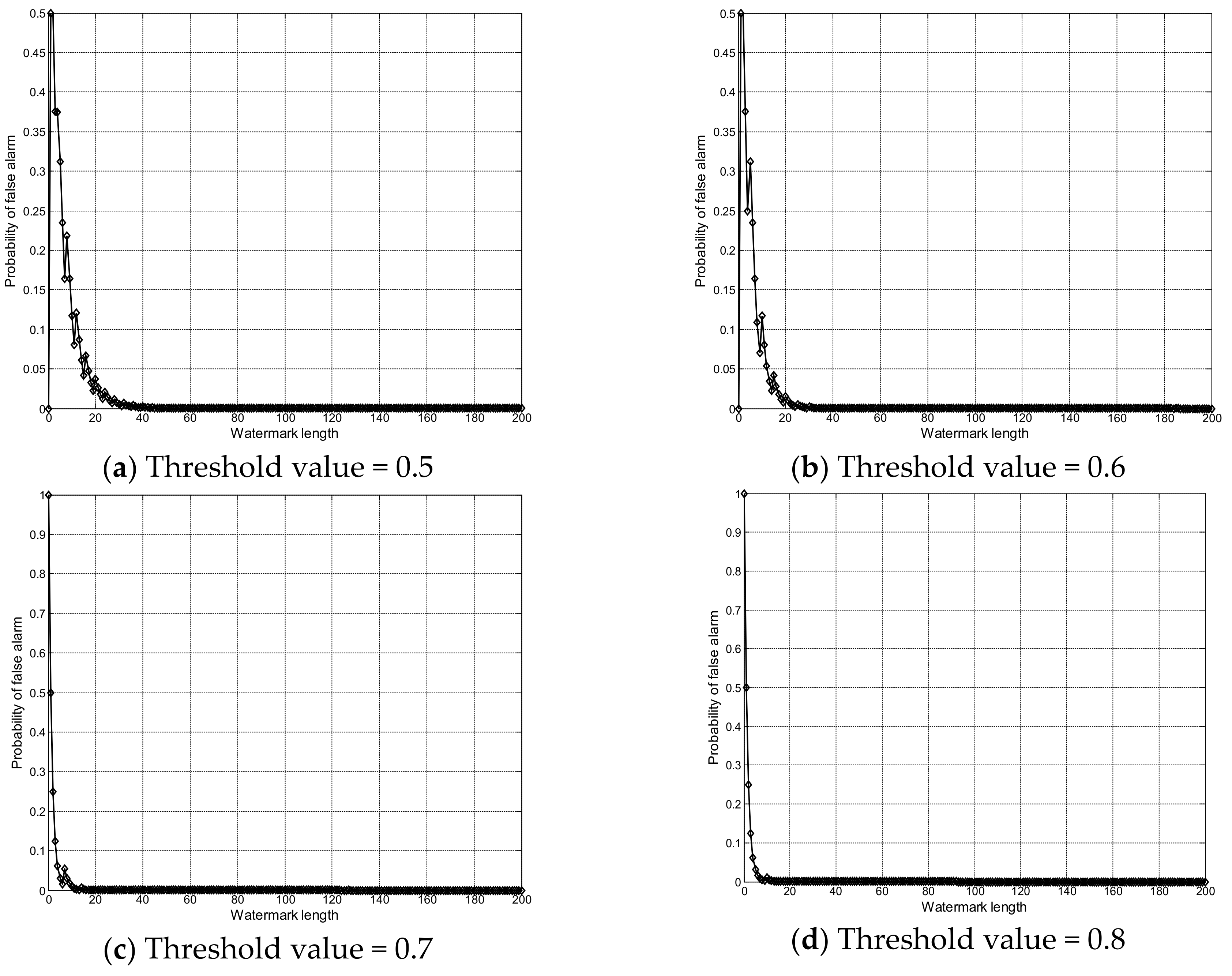
Figure 13 shows the curve relationship between false alarm probabilities with watermark length. It indicates that p f trends to zero when watermark length is greater than 40. The larger the threshold value, the smaller the length of watermark from Figure 13. According to the proposed watermarking method, the watermark length is set to be 4096, thus p f is approximately equal to zero. Therefore, we focus on the probability of watermark detection in the following section.
(2) Probability of detection
Similarly, suppose that for a watermarked image, we assumed that the effect of image distortion on the watermark is modeled as Gaussian noise with variance σ 2 , based on [22], thus the probability of detection p d can be approximated as
p d = 1 m = 0 T h 2 ( N w m ) ( 2 Q 1 Q e r f c ( Δ ¯ 4 σ ) ) N w m ( 1 2 Q 1 Q e r f c ( Δ ¯ 4 σ ) ) m  
where T h 2 = N w ( T + 1 ) / 2 1 , Δ ¯ represents the mean value of all the wavelet coefficients and e r f c ( ) is the standard complementary error function.
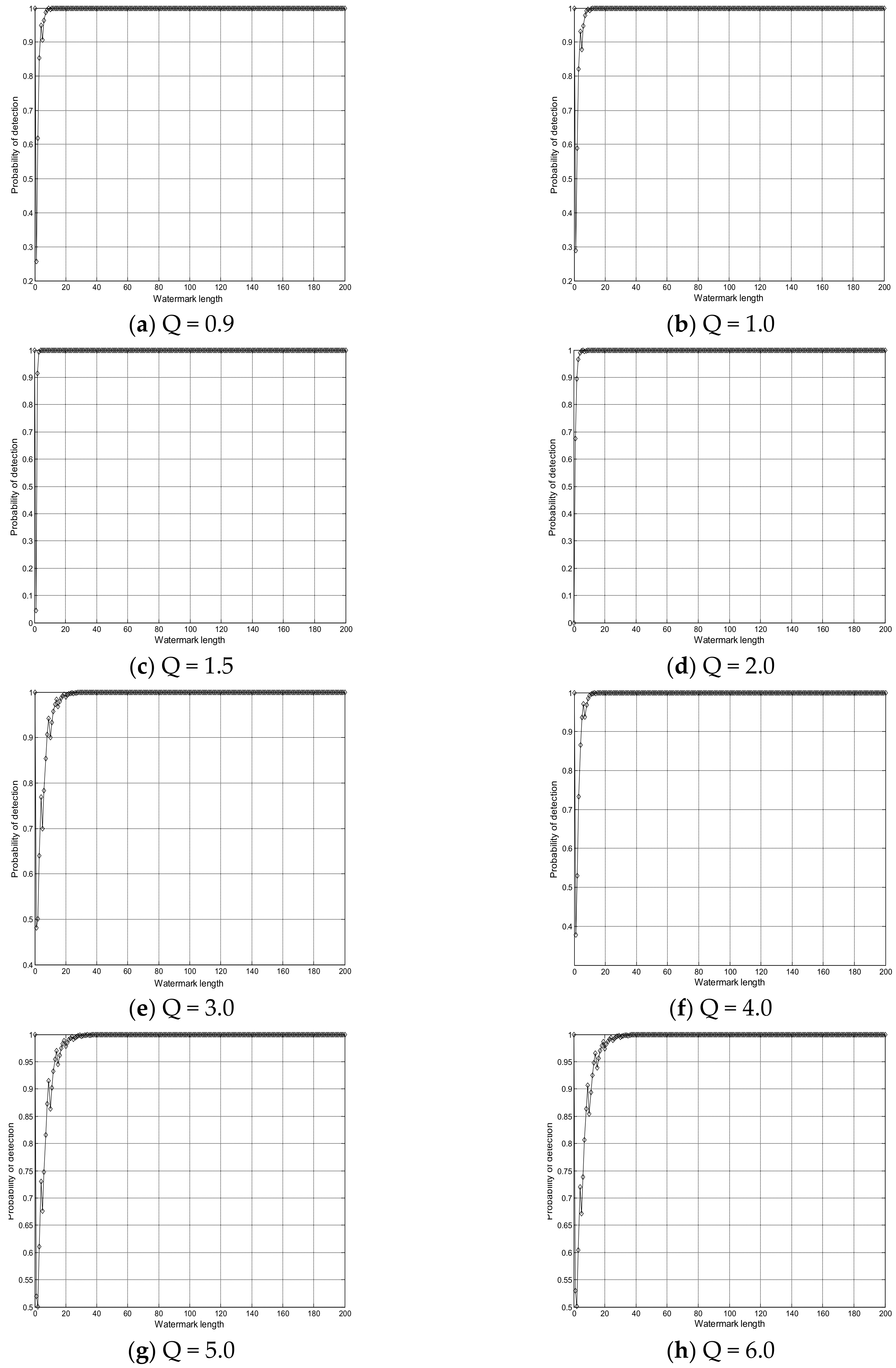
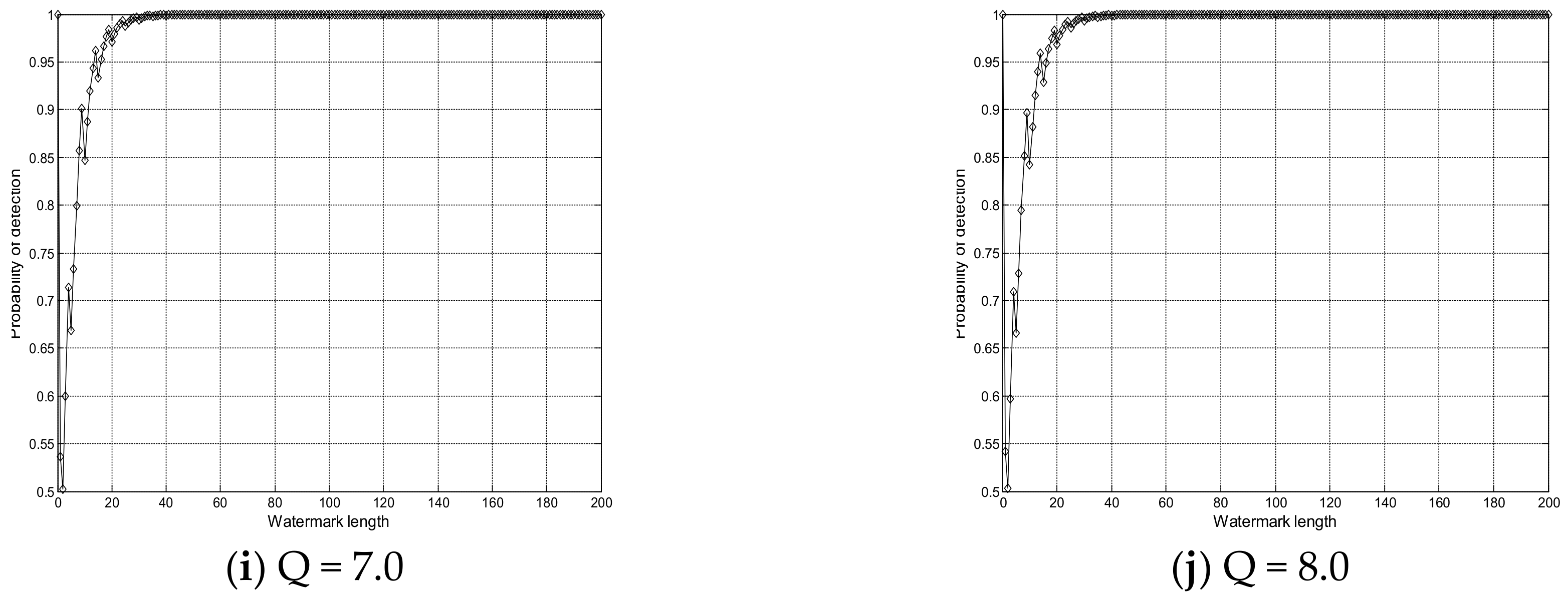
Figure 14 shows the probability of detection by different quantization parameter Q when the length of watermark belongs to (0, 200]. The smaller the quantization parameter Q, the better the performance of watermark detection. It indicates that p d trends to one when watermark length is greater than 20 in Figure 14a–j. The larger the quantization parameter Q, the worse the performance of watermark detection. It can be concluded that when the watermark length is increased, the probability of detection error can be reduced to some extent.

4.3. Comparison with Other Watermarking Method

Table 3 and Table 4 illustrate the comparison of proposed watermarking algorithm with [10,14,23] by using the NC value for the Lena and Fingerprint watermarked image. The methods in [10] and [14] were chosen on the basis of its similarity to our method. The reason for the selection of method [23] is that [23] and the proposed method in this paper use the discrete wavelet transform. In Table 3 and Table 4, we did the experiments by embedding the same watermark length of 4096 bits after watermarking as in References [10,14], and [23] into the Lena and Fingerprint images, and the PSNR of watermarked image is 45 dB. From the results in Table 3, we can see that the proposed watermarking algorithm has superior performance than [10,14,23] when resisting some common image processing attacks.
Table 4 indicates the results of attack under some geometric attacks; it shows that our watermarking algorithm also has superior performance than [10,14,23]. The main reason of the proposed watermarking is summarized as follows. One is that the watermark information is embedded into the high entropy image region; by applying this strategy, the robustness of watermarking can be improved when resisting common image processing attack. The second is that the normalization technology can achieve geometric invariance, thus it can be effectively extract the watermark data.
However, the proposed watermarking algorithm performs weakly against other distortion attacks, such as the combination of JPEG compression and Gaussian noise, global affine transformation and local random bending attack, etc. This issue will be addressed by using some feature extraction methods in our future work, which of consists of group component analysis [24,25,26], linear regression [27] and multi-kernel extreme learning method [28], etc.

5. Conclusions

In this study, a modified quantization watermarking method was proposed, which shows superior performance compared to an existing quantization watermarking algorithm. The proposed watermarking was exploited in the wavelet domain, where the wavelet has good multi-resolution and sparse representation. The main advantages of this proposed method were summarized as follows:
(1)
The high entropy image region was selected as the watermark embedding space, which improves the imperceptibility of the watermarking.
(2)
The proposed watermarking is blind, that is the watermark detection does not require the original image.
(3)
The image normalization strategy is used to designing the watermarking algorithm, which enhances the robustness of watermarking when against some geometric distortions.
Simulation results demonstrate that both the imperceptibility and robustness are well satisfied. Furthermore, the performance analysis was discussed by the probability of false alarm and detection results with different threshold value and quantization parameters.

Author Contributions

J.L. conceived the idea, designed the experiments and wrote the paper; Q.T. and X.X. helped to analyze the experimental data.

Funding

This work was supported by the Science and Technology Foundation of Jiangxi Provincial Education Department (Grant No. GJJ170922, GJJ14711), the National Natural Science Foundation of China under Grant No. 61362019.

Conflicts of Interest

The authors declare no conflict of interest.

References

  1. Asikuzzaman, M.; Pickering, M.R. An overview of digital video watermarking. IEEE Trans. Circuits Syst. Video Technol. 2017, 99, 1. [Google Scholar] [CrossRef]
  2. Qin, C.; Ji, P.; Wang, J.W.; Chang, C.C. Fragile image watermarking scheme based on VQ index sharing and self-embedding. Multimed. Tools Appl. 2017, 76, 2267–2287. [Google Scholar] [CrossRef]
  3. Zhou, J.T.; Sun, W.W.; Dong, L.; Liu, X.M.; Au, O.C.; Tang, Y.Y. Secure reversible image data hiding over encrypted domain via key modulation. IEEE Trans. Circuits Syst. Video Tech. 2016, 26, 441–451. [Google Scholar] [CrossRef]
  4. Wang, C.X.; Zhang, T.; Wan, W.B.; Han, X.Y.; Xu, M.L. A novel STDM watermarking using visual saliency-based JND model. Information 2017, 8, 103. [Google Scholar] [CrossRef]
  5. Castiglione, A.; Pizzolante, R.; Palmieri, F.; Masucci, B.; Carpentieri, B.; Santis, A.D.; Castiglione, A. On-board format-independent security of functional magnetic resonance images. ACM Trans. Embedded Comput. Syst. 2017, 16, 56–71. [Google Scholar] [CrossRef]
  6. Castiglione, A.; Santis, A.D.; Pizzolante, R.; Castiglione, A.; Loia, V.; Palmieri, F. On the protection of fMRI images in multi-domain environments. In Proceedings of the 2015 IEEE 29th International Conference on Advanced Information Networking and Applications, Gwangiu, Korea, 25–27 March 2015; pp. 24–27. [Google Scholar]
  7. Cox, I.J.; Kilian, J.; Leighton, T. Secure spread spectrum watermarking for multimedia. IEEE Trans. Image Process. 1997, 6, 1673–1687. [Google Scholar] [CrossRef] [PubMed] [Green Version]
  8. Barni, M.; Bartolini, F.; Cappellini, V.; Piva, A.A. DCT-domain system for robust image watermarking. Signal Process. 1998, 66, 357–372. [Google Scholar] [CrossRef]
  9. Kundur, D.; Hatzinakos, D. Digital watermarking using multiresolution wavelet decomposition. In Proceedings of the International Conference on Acoustic, Speech and Signal Processing, Seattle, WA, USA, 12–15 May 1998; pp. 2969–2972. [Google Scholar]
  10. Chen, L.H.; Lin, J.J. Mean quantization based image watermarking. Image Vision Comput. 2003, 21, 717–727. [Google Scholar] [CrossRef]
  11. Watson, A.B.; Yang, G.Y.; Solomon, J.A.; Villasenor, J. Visibility of wavelet quantization noise. IEEE Trans. Image Process. 1997, 6, 1164–1175. [Google Scholar] [CrossRef] [PubMed] [Green Version]
  12. Chen, B.; Wornell, G.W. Quantization index modulation: A class of provably good methods for digital watermarking and information embedding. IEEE Trans. Inf. Theory 2001, 47, 1423–1443. [Google Scholar] [CrossRef]
  13. Perez-Gonzalez, F.; Mosquera, C.; Barni, M.; Abrardo, A. Rational Dither Modulation: A high-rate data-hiding method invariant to gain attacks. IEEE Trans. Signal Process. 2005, 53, 3960–3975. [Google Scholar] [CrossRef]
  14. Li, Q.; Cox, I.J. Using perceptual models to improve fidelity and provide resistance to valumetric scaling for quantization index modulation watermarking. IEEE Trans. Inf. Forensics Secur. 2007, 2, 127–139. [Google Scholar] [CrossRef]
  15. Kalantari, N.K.; Ahadi, S.M. Logarithmic quantization index modulation for perceptually better data hiding. IEEE Trans. Image Process. 2010, 19, 1504–1518. [Google Scholar] [CrossRef] [PubMed]
  16. Zareian, M.; Tohidypour, H.R. A novel gain invariant quantization-based watermarking approach. IEEE Trans. Inf. Forensics Secur. 2014, 9, 1804–1813. [Google Scholar] [CrossRef]
  17. Munib, S.; Khan, A. Robust image watermarking technique using triangular regions and Zernike moments for quantization based embedding. Multimed. Tools Appl. 2017, 76, 8695–8710. [Google Scholar] [CrossRef]
  18. Chauhan, D.S.; Singh, A.K.; Kumar, B.; Saini, J.P. Quantization based multiple medical information watermarking for secure e-health. Multimed. Tools Appl. 2017, 8, 1–13. [Google Scholar] [CrossRef]
  19. Dong, P.; Brankov, J.G.; Galatsanos, N.P.; Yang, Y.Y.; Davoine, F. Digital Watermarking robust to geometric distortions. IEEE Trans. Image Process. 2005, 14, 2140–2150. [Google Scholar] [CrossRef] [PubMed]
  20. Akhaee, M.A.; Sahraeian, S.M.E.; Sankur, B.; Marvasti, F. Robust scaling-based image watermarking using maximum-likelihood decoder with optimum strength factor. IEEE Trans. Multimed. 2009, 11, 822–833. [Google Scholar] [CrossRef]
  21. Kwitt, R.; Meerwald, P.; Uhl, A. Efficient detection of additive watermarking in the DWT-domain. In Proceedings of the 17th European Signal Processing Conference, Glasgow, UK, 24–28 August 2009; pp. 2072–2076. [Google Scholar]
  22. Fan, M.Q.; Wang, H.X. Chaos-based discrete fractional Sine transform domain audio watermarking scheme. Comput. Electr. Eng. 2009, 35, 506–516. [Google Scholar] [CrossRef]
  23. Lyu, W.L.; Chang, C.C.; Nguyen, T.S.; Lin, C.C. Image watermarking scheme based on scale-invariant feature transform. KSII Trans. Internet Inf. Syst. 2014, 8, 3591–3606. [Google Scholar]
  24. Zhou, G.X.; Zhang, Y.; Mandic, D.P. Group component analysis for multiblock data: Common and individual feature extraction. IEEE Trans. Neural Netw. Learn Syst. 2016, 27, 2426–2439. [Google Scholar] [CrossRef] [PubMed]
  25. Zhang, Y.; Nam, C.S.; Zhou, G.; Jin, J.; Wang, X.; Cichocki, A. Temporally constrained sparse group spatial patterns for motor imagery BCI. IEEE Trans. Cybernet. 2018, 9, 1–11. [Google Scholar] [CrossRef] [PubMed]
  26. Ma, J.X.; Zhang, Y.; Cichocki, A.; Matsuno, F. A novel EOG/EEG hybrid human–machine interface adopting eye movements and ERPs: Application to robot control. IEEE Trans. Biomed. Eng. 2015, 62, 876–889. [Google Scholar] [CrossRef] [PubMed]
  27. Wang, H.Q.; Zhang, Y.; Waytowich, N.R.; Krusienski, D.J.; Zhou, G.X.; Jin, J.; Wang, X.Y.A. Discriminative feature extraction via multivariate linear regression for SSVEP-based BCI. IEEE Trans. Neural Syst. Rehabil. Eng. 2016, 24, 532–541. [Google Scholar] [CrossRef] [PubMed]
  28. Zhang, Y.; Wang, Y.; Zhou, G.X.; Jin, J.; Wang, B.; Wang, X.Y.; Cichocki, A. Multi-kernel extreme learning machine for EEG classification in brain-computer interfaces. Expert Syst. Appl. 2018, 96, 302–310. [Google Scholar] [CrossRef]
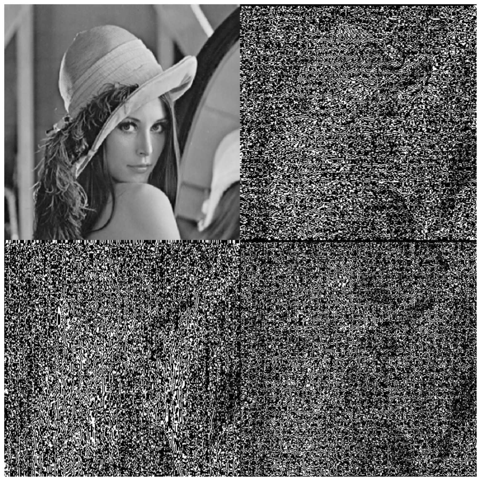
Figure 1. Wavelet transform of the Lena image using one-scale, which are then decomposed into one low-frequency sub-band and three directional sub-bands.
Information 09 00194 g001
Figure 2. Flow chart of the proposed watermarking method. (a) Embedding; (b) Detection.
Information 09 00194 g002aInformation 09 00194 g002b
Figure 3. Original, watermarked and difference images by the proposed method: Fingerprint, Lena, Barbara, Crowd, Mandrill, Boat, Mit and Bridge. In each image, the left part, middle part and the right part are represented the original image, the watermarked image, and the absolute difference between the watermarked and the original image, respectively.
Information 09 00194 g003aInformation 09 00194 g003b
Figure 4. (a) High-pass filtering attack; (b) detector response.
Information 09 00194 g004
Figure 5. (a) Low-pass filtering attack; (b) detector response.
Information 09 00194 g005
Figure 6. (a) Gaussian noise; (b) detector response.
Information 09 00194 g006
Figure 7. (a) JPEG compression; (b) detector response.
Information 09 00194 g007
Figure 8. (a) Histogram equalization; (b) detector response.
Information 09 00194 g008
Figure 9. (a) Scaling attack (scaling factor is 0.25); (b) detector response.
Information 09 00194 g009
Figure 10. (a) Rotation attack (angle = 15°); (b) detector response.
Information 09 00194 g010
Figure 11. (a) Cropping attack; (b) detector response.
Information 09 00194 g011
Figure 12. (a) Brightness adjustment attack; (b) detector response.
Information 09 00194 g012
Figure 13. Probability of false alarm versus watermark length.
Information 09 00194 g013
Figure 14. Probability of detection with respect to quantization parameter.
Information 09 00194 g014aInformation 09 00194 g014b
Table 1. Experimental parameter settings.
Parameter NameConfiguration
Experimental platformWindow 7, MATLAB R2016a
Test imagesFingerprint, Lena, Barbara, Crowd, Mandrill, Boat, Mit and Bridge
Image size512 × 512
Wavelet filters of DWTbiorthogonal CDF 9/7
Watermark length (bits)4096
Decomposition level Three-level
Robustness evaluationNormalized Correlation coefficient
Table 2. Computational time of the proposed method with different image (unit: s).
ImageFingerprintLenaBarbaraCrowdMandrillBoatMitBridge
Time10.209510.493010.63989.93769.879510.417210.688310.5062
Table 3. The results of attack under image processing (NC).
ImagesLenaFingerprint
Attacks[10][14][23]Proposed[10][14][23]Proposed
Gaussian filtering (3 × 3)0.68590.70240.73590.84350.72310.74580.71900.8729
Median filtering (3 × 3)0.65300.69470.67280.78460.67140.72560.69800.8105
Additive noise ( σ = 20)0.53170.68480.61690.75820.57340.70230.63470.7664
Histogram equalization0.72150.76490.75530.80650.74030.78910.76220.8458
JPEG (10)0.35020.26170.29840.59360.32780.29210.30400.5983
JPEG (30)0.51290.45620.48900.70240.53430.48160.49530.7191
JPEG 2000 (20)0.67490.34810.68720.76580.69390.41240.70090.7815
JPEG 2000 (50)0.79230.67380.81550.87420.80110.69340.82250.8901
JPEG 2000 (90)0.92580.90160.93450.95030.93120.90890.93960.9647
Brightness adjustment0.80330.68360.75290.87340.81220.72400.76590.8936
Table 4. The results of attack under geometric distortions (NC).
ImagesLenaFingerprint
Attacks[10][14][23]Proposed[10][14][23]Proposed
Scaling (1/2)0.64340.86270.85390.89100.65130.84760.82080.9025
Scaling (1/4)0.56260.76430.80270.82580.58420.77190.78940.8032
Scaling (1/8)0.30150.53540.57680.65240.31160.52080.58330.6917
Rotation (5°)0.79040.85250.91820.93160.82260.87340.92460.9479
Rotation (10°)0.65200.79380.87480.91220.64190.78560.88450.9065
Rotation (20°)0.59390.68260.75300.81240.60050.69200.76520.8008
Center Cropping (25%)0.64130.69570.76280.78350.65310.71240.77850.7931
JPEG (50) + Scal. (0.9)0.63220.49580.65590.70230.64140.51700.67710.7246
JPEG (30) + Scal. (0.7)0.54210.39820.58160.62190.55260.39900.59020.6334
JPEG 2000 (50) + Scal. (0.8)0.60200.36590.64280.65460.61750.40320.65330.6750
JPEG 2000 (30) + Scal. (0.5)0.45210.30560.53550.57690.46090.32480.55800.5906