Article

An Anti-Collision Algorithm for RFID Based on an Array and Encoding Scheme

School of Computing Science & Engineering, Xi’an Technological University, Xi’an 710021, China
*
Author to whom correspondence should be addressed.
Information 2018, 9(3), 63; https://doi.org/10.3390/info9030063
Submission received: 26 January 2018 / Revised: 1 March 2018 / Accepted: 7 March 2018 / Published: 10 March 2018
(This article belongs to the Section Information and Communications Technology)

Abstract

:
In order to solve the problem of tag collision in Radio Frequency Identification (RFID) system, the paper proposes a Multi-Bit Identification Collision Tree (MICT) algorithm based on a collision tree. The algorithm uses an array scheme to mark the collision bits in the identification process, and determines the collision information according to the first few bits of the tag, which can effectively reduce the number of recognitions and the amount of communication data. The testing results show that the proposed algorithm reduces the time complexity by about 38% and the communication complexity by about 27% compared to existing collision-tree-based algorithms. Through theoretical analysis and experimental evaluation, the MICT algorithm has obvious advantages in terms of time and communication complexity compared to the other typical algorithms. The algorithm can be applied to the field of RFID-related systems to significantly improve the system efficiency.

1. Introduction

RFID technology is a non-contact intelligent identification technology. Compared to traditional automatic identification technology, it has the advantages of small volume, low cost, large storage, high security, and reusability. As a result, RFID is rapidly replacing outdated barcode systems and various smartcard systems. RFID systems have great application value in the fields of industrial production, logistics, cargo and health management, safety inspection, and intelligent transportation [1,2,3,4]. However, in the process of RFID identification of multiple tags simultaneously, the collision between tags is a key issue affecting the efficiency of RFID identification.
Several classical algorithms have been presented, such as the ALOHA algorithm [5,6], the Query Tree (QT) [7,8,9,10] algorithm, the Collision Tree (CT) algorithm [11], etc. These anti-collision algorithms can be divided into two categories: probabilistic methods based on ALOHA, and deterministic methods based on tree structure [12,13,14,15]. The probabilistic identification algorithms are simple to design and the identification time is short, but there will be a “tag hunger” problem. The deterministic algorithms ensure that all tags in the identified range are identified, but often do not perform well in communication efficiency. Recently, several algorithms such as tag grouping [16,17], bit tracking [18,19], and multi-bit identification have been proposed to improve the performance of RFID identification. Jung has proposed an Optimized Binary Search with Multiple Collision Bits Resolution Anti-Collision Algorithm (OBS-MCBR) [20]. In this algorithm, the collision bits are extracted and coded, and the collision location information is restored according to the collision situation. The performance of the algorithm is 30% higher than that of the CT algorithm. Wang has put forward an anti-collision algorithm based on multi-bit identification (MBI) [21]. The algorithm makes full use of the collision information of a certain length, and uses a distinguishable grouping scheme to group the specific query prefixes. Thus, several collision bits can be continuously identified when multiple collisions occur. However, the performance of proposed algorithms still has low efficiency.
The CT algorithm only updates the query prefix for the collision location, which reduces unnecessary queries and eliminates the idle time slot. In addition, in the recognition process, the CT algorithm does not need the label memory information; the algorithm design is simple and effective, and has good improvement space.
This paper proposes a Multi-bit Identification Collision Tree (MICT) algorithm based on the CT algorithm. The algorithm uses an array scheme to mark the collision bits, and adopts the coding scheme to analyze the collision bits, which can quickly identify the collision of multiple collision bits. The experimental results show that the new algorithm has a better performance in terms of time complexity and communication complexity compared to existing algorithms.

2. Problem Identification

In the RFID system, the reader and the tag communicate with each other through radio frequency signals. The channel is a signal transmission medium, and its role is to transmit the signal carrying information from the sender to the receiver. When multiple readers or multiple tags transmit RF signals at the same time, the signals will collide with each other in the wireless channel, causing collision problems. The reader cannot receive the correct signal information or the signal fails to be sent. The collision types of RFID systems include tag collision and reader collision, in which reader collision includes reader-tag collision and reader-reader collision.

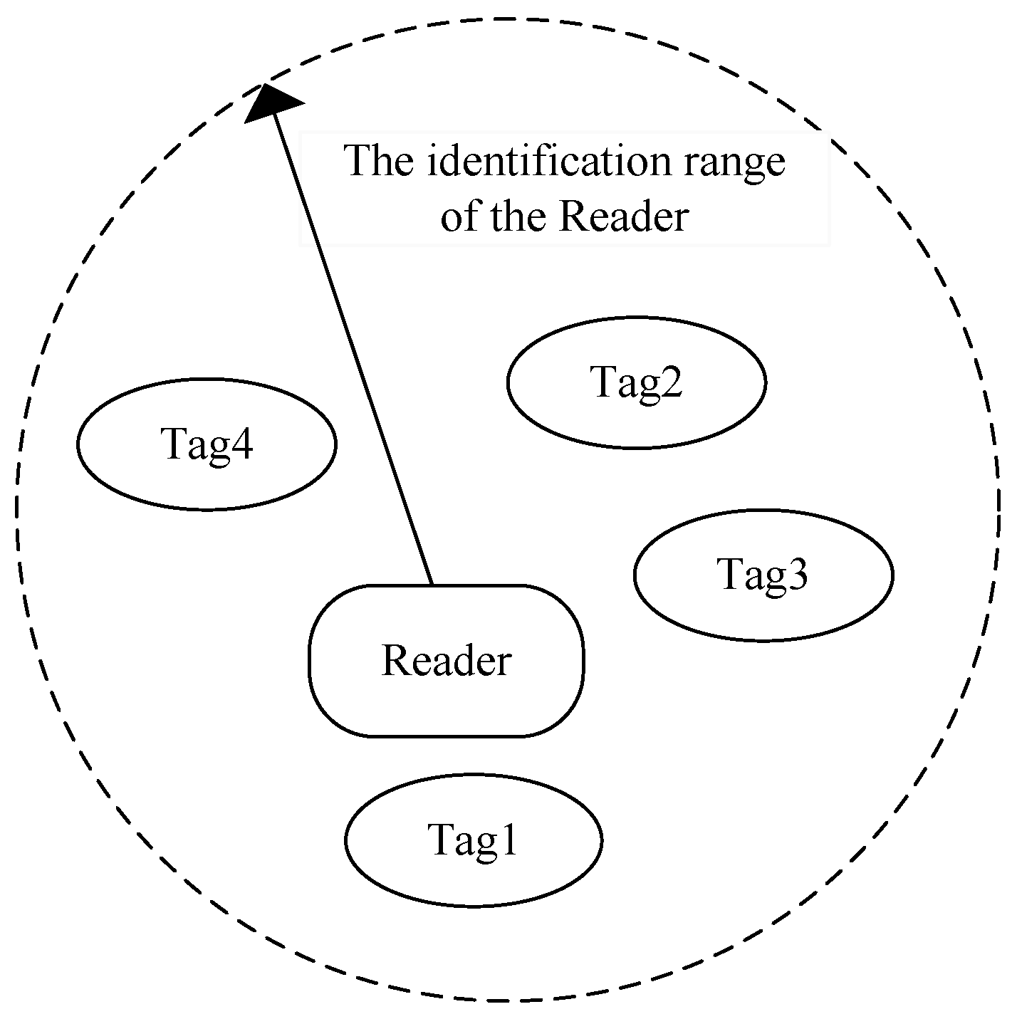
2.1. Tag-Tag Collision

Tag-tag collision refers to the collision problem between multiple tags, usually occurs when multiple tags send data signals to the reader at the same time, as shown in Figure 1.
Pluralities of tags within a reader identification range respond to the reader’s command after receiving the reader's command. When two or more tags send data signals to the reader at the same time, the data signals interfere with each other in the wireless channel. At this time, the reader cannot correctly receive the data signals of these tags, causing communication failure.

2.2. Tag-Reader Collision

Tag-reader collision occurs in a multiple readers identification scenario, as shown in Figure 2.
Tag-reader collision means that when a tag is in the identification range of two or more readers at the same time, multiple readers will send a command to a tag and the tag fails to process the signal after it receives signals from multiple readers simultaneously. Tag 2 in Figure 2 is in the identification range of Reader 1 and Reader 2 at the same time, and cannot respond to either of them when both signals are received at the same time. As a result, Readers 1 and 2 cannot read the Tag 2 information.

2.3. Reader-Reader Collision

Readers-reader collision refers to the fact that when one tag is within the recognition range of two or more readers simultaneously, one or more readers cannot receive the tag signal due to the frequency interference among multiple readers.
In industrial production, commodity storage, and other RFID applications, it is necessary to fix multiple readers in one space to form a small identification area network to ensure that objects in this space can be identified. At this time, the recognition areas of multiple readers overlap each other to form interference, as shown in Figure 3. Due to the restriction of the radio frequency identification method, the readers that are not covered by the identification area also interfere with signals due to the electromagnetic waves, and the more readers are arranged, the greater the probability of collisions between readers.
This paper mainly focuses on tag-tag collision problems. Based on deep research into a large number of related algorithms, a new multi-tag collision avoidance algorithm is proposed, which aims to provide reference and support for the application of RFID in multi-tag identification research through algorithm theory research.

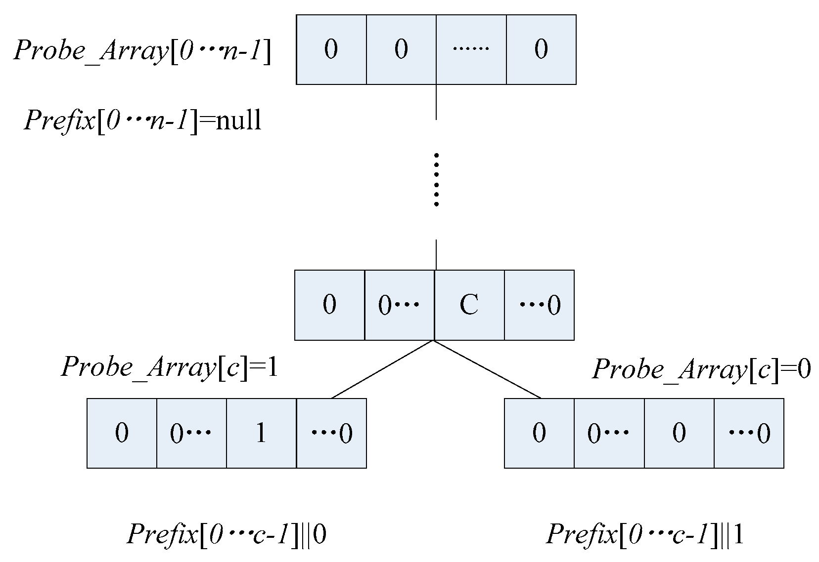
3. Array Storage Scheme

3.1. Description of the Array Storage Scheme

In QT and CT algorithms, a stack can be adopted to store the prefixes in the identification process of tags. In the initial recognition, the reader presses an empty string into the stack. If the stack is not empty, a binary string is popped as a query prefix and the reader sends the prefix and waits for the response of tags.
In the array storage scheme, the tag side retains the “no memory” feature of the CT algorithm and does not require any setting of tags. After receiving the reader’s query command, the tag’s IDs are compared to the received prefix. If the front parts of the ID numbers match the prefix, the tags send the remaining numbers to the reader; if not, the tags do nothing. Unlike the stack structure, the reader sets two arrays, as shown in Figure 4. One of them, called Probe_array[], is used to record the collision information of the label during each round of recognition. Another array, Prefix[], is used to store the query prefixes. If the ID length of the tag to be identified is n, the length of both arrays is set to m, which means there are two arrays, Probe_array[0…n-1] and Prefix[0…n-1]. For Probe_array[0…n-1], a collision is represented with the value 1, and 0 indicates no collision. Because all bits of array Probe_array are 0, all states of collision are eliminated. In the initialization phase of the identification, all bits of array Probe_array are set to 0. In the identification phase, assuming that the reader sends a query prefix and tags returning the ID message, the collision bits are indicated by c. The reader will set the Probe_array[c] to 1, and then update the prefix by adding one bit, that is Prefix [0 ... c-1] || 0. The reader sends a prefix to tags to query the left branch node; if the left branch nodes are successfully recognized, the Probe_array[c] will be set to 0, which means that the collision here has been eliminated, and prefix Prefix[0 ... c-1] || 1 is used to query the right branch nodes.

3.2. Example and Comparison of Schemes

In order to illustrate the implementation steps of the array storage scheme more intuitively, the stack in the CT algorithm is replaced by two arrays. Assume that three labels, A, B, and C, are to be identified, with the IDs A: 11010010; B: 00110110; and C: 10101101. The identification process is shown in Table 1.
The symbol x indicates the highest collision bit, and because the query prefix of the CT algorithm is updated only one bit at a time, the decoding state behind the highest collision bit is represented as -. At the beginning of identification, all elements in Probe_array[] are set to 0. First, the reader sends an empty string (ε), and all the tags respond to the reader’s identification range. Secondly, the reader finds the highest collision bit first, and Probe_array[0] = 1. The query prefix is updated one bit later, and becomes 0. The reader sends the prefix with a unique tag for B’s response, and Tag B is successfully identified. Then, the prefix becomes 1 and Probe_array [0] = 0. The reader sends the prefix again, and the decoded state is 1× ------. The reader knows that the highest collision bit is in the second bit, and set the Probe_array [1] = 1. The query prefix becomes 10. The reader sends the prefix, no collision occurs, and tag C is successfully identified. Then, the prefix becomes 11, Probe_array [1] = 0 and Tag A is successfully identified. At this time, all the elements in Probe_array[] are 0, which indicates that all collisions have been eliminated and all tags are identified.
The CT algorithm requires 16 bits to identify three tags using the array, and the stack storage takes 22 bits. According to the EPC GEN2 standard, the length of tags’ ID is set to 96 bits, and the IDs are taken in random number mode. By using MATLAB tools, the average number of bits per cycle required was simulated with tag numbers ranging from 100 to 600 with steps of 100 in Table 2. The decimal number in the Table 2 represents the ratio of the total number of bits produced to the identification cycles. It can be seen that the advantage of the array storage scheme in storage space is more obvious in a large-scale tag environment.

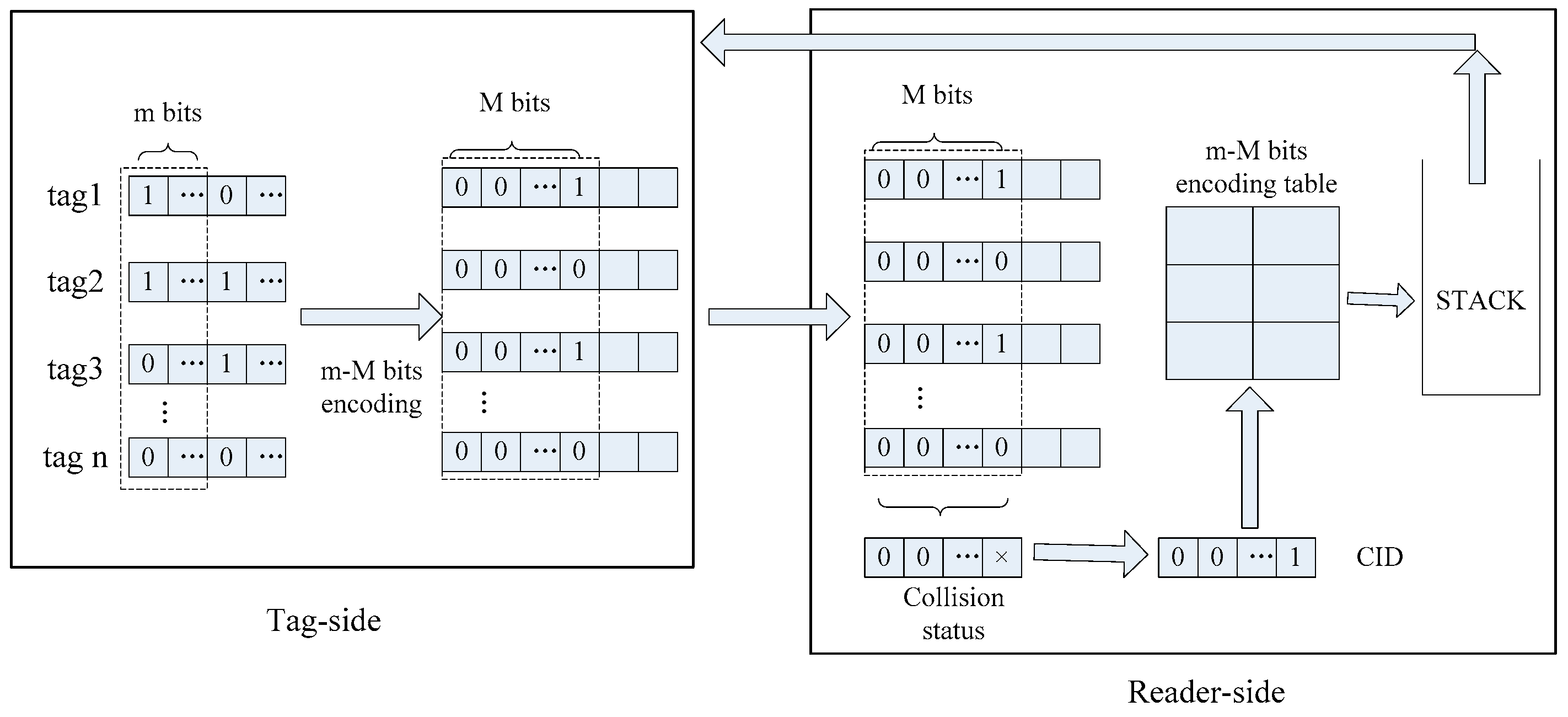
4. Tag Encoding Scheme

One of the effective ways of improving the recognition efficiency of the tree anti-collision algorithm is using the prefix updating of the collision bit according to the collision decoding situation. In the process of each response of the tag, selecting the first m bits of tags as the query prefix to encode the m-bit IDs into the encoded bits of M (M = 2m) bits is an effective method.
Since the IDs are also encoded by 0 and 1, and there is only one 1 in each code of M bits, the position of each bit is different. According to such a characteristic, when a collision occurs, a query prefix can be generated based on the characteristic of encoding to achieve the purpose of multi-bit identification. Table 3 and Table 4 list the codes corresponding to m = 2 and m = 3 respectively.
The coding scheme can be applied in the CT algorithm. In this way, the reader updates the query prefix according to the previous M-bit collision condition. The query prefix can be updated from 1 bit to m bits in each collision cycle, and the total query cycles will be reduced. The identification process is shown in Figure 5.
The first m bits of a tag’s ID are encoded and sent to the reader. After the reader receives the label code, it decodes the collision of the previous M bits. The M bits binary string is composed of the characteristic ID (CID), and the reader checks the encoding list stored in the reader to obtain the corresponding collision bit ID. The reader updates the query prefix according to the collision bit ID, pushes it into the stack, and sends a query prefix to the label. The loop continues until all tags have been identified.

5. An Anti-Collision Algorithm Based on an Array and Encoding Scheme

Based on advantages of using array storage to reduce the reader’s memory space and using the coding scheme to reduce the number of query, a multi-bit identification algorithm is proposed in this section.

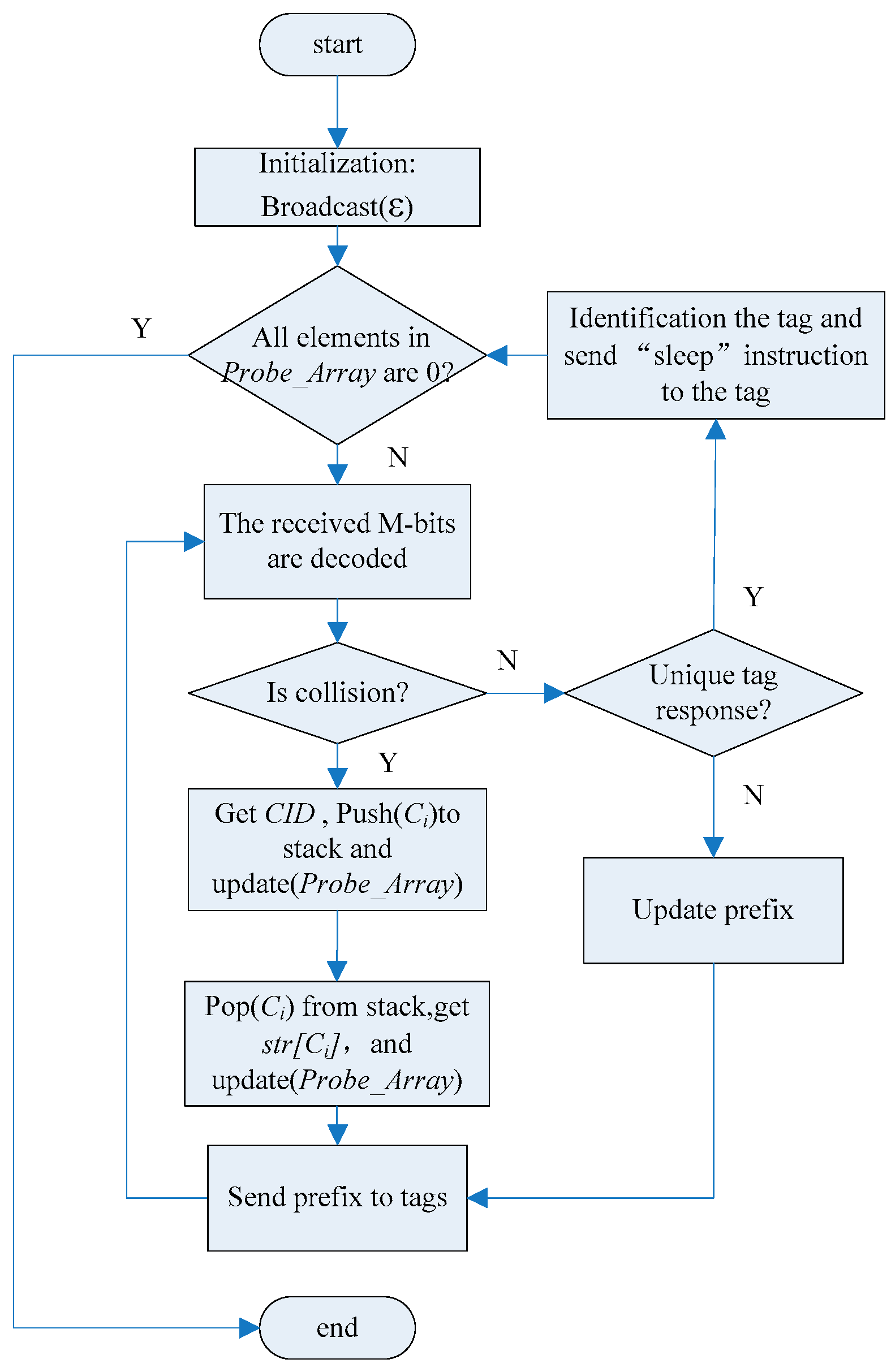
5.1. Algorithm Description

For the implementation of the algorithm under different states of the reader, the paper defines the reader commands as follows.
Broadcast instruction: the reader will broadcast the prefix to tags. In the initial state, the prefix is an empty string.
Update instruction: updating the value of Probe_array[] according to the value of CID.
Read instruction: the reader reads the ID information of the tags according to the instructions.
Sleep instruction: after the reader sends the instructions to a tag, the tag does not respond to the instructions of the reader.
The encoding scheme is stored using a two-dimensional character array, as shown in Table 5. Since the coding scheme converts the ID string per m bit into a binary string of M bits, the reader identifies received tag IDs in an identification interval of each length of M. Due to the characteristics of the code, the reader will generate prefixes based on the number of collisions in the CID.
Each collision location can be recorded to obtain the query prefix based on the corresponding instructions for each collision position. If the reader decoder is “××0×”, then CID is “1101”, and the collision occurred at the position 0, 2, and 3. The reader sends Request (0, Str), Request (2, Str), and Request (3, Str) to itself to obtain the encodings “00”, “10”, and “11” in the 2-d array. Subsequently, the reader will update the prefixes based on the obtained encodings.
The algorithm flow chart of the reader side is described in Figure 6, and both identification steps of the reader side and the tag side are described below.
Reader-side identification steps:
(1) In the initial stage of the query, the reader sends an empty string to tags and all the tags within the identification range respond to it.
(2) The reader takes the M bit as the identification interval, replies to the received M-bits IDs, and decodes the remaining ID information. If the M-bits IDs do not collide and the remaining bits have collisions, the query prefix is updated and the query continues. If only the unique tag replies to its own ID, the tag is identified. Reader reads the information of the tag, and then sends the “Sleep” instruction to keep the tag in sleep mode and skip to step 5. If there is a collision, it skips to step 3.
(3) According to the decoding results, the bit of the collision is set to 1, and the bit with no collision is marked as 0. The reader get Ci (0 ≤ I < M) according to the position of 1 in the CID, pushes Ci into the stack, and sets the m-bits value of Probe_array [0...n] to 00 ... a, where a represents the number of 1 in CID.
(4) Extract an element Ci from the stack, and get Str[Ci] according to the two-dimensional character array. Meanwhile, the corresponding position of 'a' in the Probe_array[] is decreased by 1, and let Prefix = Prefix+Str[Ci]. If a in the current identification section is changed to 0, it continues to extract an element Ci from the stack, and let Prefix = Prefix[0,C']+Str[Ci], where, C' is the last collision position. The reader broadcasts prefix to tags; skip to step 2.
(5) If all the elements in Probe_array[] are 0, it means that all the tags have been correctly identified and the identification process is finished.
Tag-side identification steps:
After receiving the query prefix, the first m-bit IDs of the tags matching the query prefix are encoded into M-bit data, and the remaining IDs are returned in addition to the query prefix.

5.2. Example of Algorithm

The execution steps of the multi-bit collision tree algorithm are described as follows. Here, m = 2 in the m-M bits scheme, which means the first two bits of the tag response part are encoded. Suppose that the six tags are A, B, C, D, E, and F, as shown in Table 6. Their IDs are A: 00000101; B: 00101011; C: 00111111; D: 01010100; E: 10110111; F: 11001011.
It can be seen from Table 6 that the reader sends an empty string ε in the first step, and all the tags in the identification range respond and convert the first two of their ID numbers into four-digit codes and send them to the reader. The reader obtains the CID value as 1111 after decoding. There are four collision bits, so the first two bits in the Probe_array[] array are set to 04. At the same time, the reader gets the values of the four Ci values 0, 1, 2, and 3 according to the position of 1 in the CID and pushes them into the stack. An element 0 is popped from the stack, and the value of 4 in the Probe_array[] is decreased by one. The reader searches the two-dimensional array, obtains the query prefix 00, and sends it to the tags. After obtaining the query prefix, the tag that matches the query prefix encodes the first two digits of the ID except for the prefix, and replies to the remaining ID. The reader decodes the ID information of tags that replied to obtain CID = 1101, which indicates that there are three collision bits, and the corresponding two bits in the Probe_array[] are set to 03. The reader obtains three values of 0, 2, and 3 according to the position of 1 in the CID, and pushes them into the stack. In the third query cycle, the reader gets the query prefix 0000, sends the prefix to tags, and the value of 3 in the Probe_array[] is decreased by one. Only a unique tag responds, so tag A is identified. The reader sends a “sleep” instruction, and tag A is in silence. Continue to pop “2” from the stack; the reader accordingly gets the query prefix 0010 and broadcasts it. Simultaneously, the reader changes the value of the corresponding position in the Probe_array[], by which the label B is correctly identified, and the tag C is identified in this step. In this case, the value of the second m bits in the Probe_array[] has been changed to 00, which indicates that the collision at this position has been eliminated and returned to the previous m bits. An element is popped from the stack, and Probe_array[] will change its value 03 to 02. The reader obtains the query prefix and sends it to the tags. Follow the steps described above, tags D, E, and F are identified. Finally, the values of all positions in Probe_array[] are 0.

5.3. Analysis of Algorithm Performance

5.3.1. Time Complexity Analysis

Time complexity refers to the number of query–response cycles required to complete the identification of all labels in a collection of tags. Suppose that the number of identified tags is n; there are only the collision nodes and the identification nodes in the process of establishing the M-tree. The total number of nodes is expressed as follows:
N = n c + n i d
where n c is the collision nodes and n i d indicates the identification nodes. Each time a collision occurs, the collision nodes generate branch nodes accordingly, and the identified tag corresponds to the nodes whose degree is 0. We thereby obtain the following equation:
n i d = n
In the worst case, this algorithm implements the identification process of n tags to form an overriding tree.
According to the m-M bits scheme, if the intermediate nodes collide, the number of query prefixes can be 2, 3, ..., m ..., M. The collision tree may be a full 2-ary tree, a full 3-ary tree, a full M-ary tree, or a mixed tree of 2 to 2m, so the number of nodes required for different limits is calculated here.
When the number of query prefixes generated by collision is 2, which means the whole collision tree is a full binary tree, the time slot derivation process according to CT algorithm can be obtained as follows:
N = 2 n 1
When the number of query prefixes generated by the collision is 3, that is, when the whole collision tree is a full trinary tree, the nodes in the tree have only nodes with a degree of 3 and a degree of 0 and a root node. On the other hand, suppose that the number of nodes with the degree of 0 is N0 and the degree of 3 is N3, then the number of collision nodes n c = N 3 , the number of the identified nodes n i d = N 0 . The total number of nodes is as follows:
N = N 3 + N 0
Let B be the total number of branches present in a complete trinary tree; because any node other than the root node in the tree corresponds to a branch, the total number of nodes in a complete trinary tree can be represented by the total number of branches, as follows:
N = B + 1
Each intermediate node in the tree has three branches, and the lowest child node has no branch, so the number of branches B can be expressed as follows:
B = 3 N 3
From Equations (5) and (6), the following equation can be obtained:
N = 3 N 3 + 1
From Equations (4) and (7), the equation can be obtained as follows:
N 3 = ( N 0 1 ) / 2
Substituting Equation (8) into Equation (4), the following equation can be obtained:
N = ( 3 N 0 1 ) / 2
Because the nodes of degree 0 are the bottom-most identifying nodes in the tree, combined with Equation (2), the following equation can be derived:
N = ( 3 n 1 ) / 2
According to the above derivation, the number of nodes of the complete M-ary tree can be obtained as follows:
N = ( m n 1 ) / ( m 1 )
where m is the number of coded bits in the m-M coding scheme. Each time a collision occurs, the collision node may generate 2 to 2m prefixes, so the average of the number of nodes is used to represent the time complexity of the algorithm. T(n) is the time complexity, expressed as follows:
T ( n ) = N ¯ = m = 2 2 m ( m n 1 ) / ( m 1 ) 2 m 1
Think of Equation (11) as a function of m, and the function can be expressed as follows:
f ( m ) = ( m n 1 ) / ( m 1 )
Derive Equation (13) to get Equation (14):
f ( m ) = ( 1 n ) / ( m 1 ) 2
Since n is greater than 1 and m is greater than or equal to 2, the derivative f ( m ) is always less than 0, which indicates that the value of f ( m ) decreases as m increases. When n is equal to 2, N = 2 n 1 . As n increases, the value of N is less than 2n-1, and the following inequality is established:
N ¯ 2 n 1
Therefore, it is proved that the proposed MICT algorithm is superior to the CT algorithm in terms of time complexity.

5.3.2. Communication Complexity Analysis

Communication complexity refers to the amount of data transmitted between the reader and the tag in the RFID tag anti-collision algorithm. The communication complexity includes both the amount of data sent by the reader, which is called the reader-side communication complexity, and the tag side of the binary number of replying, which is called the tag-side communication complexity. In the RFID system, the communication complexity also represents the energy consumption. Usually, the greater the amount of data transmitted, the higher the energy consumption of the system.
Let C(n) be the communication complexity of MICT algorithm, CR(n) is the reader-side communication complexity, CT(n) is the tag-side communication complexity, and they satisfy the following relationship:
C ( n ) = C T ( n ) + C R ( n )
Let lcom be the length of the instruction sent by the reader. lpre,i is the length of the query prefix in the ith cycle, and lrep,i is the length of the binary string sent by tags. Equation (16) can be expressed as follows:
C ( n ) = i = 1 T ( n ) ( l c o m + l p r e , i ) + i = 1 T ( n ) l p r e , i
Since the first m bits are encoded each time when the tag is returned to the ID message. The tag-side communication complexity can be changed as follows:
C R ( n ) = i = 1 T ( n ) l p r e , i = i = 1 T ( n ) l r e p , i + 2 m m
The length of l’rep,i is equal to the length of the tag’s ID minus the length of lpre,i, and can be expressed by the following equation:
l I D = l p r e , i + l r e p , i
Therefore, the communication complexity of the MICT algorithm can be obtained via Equations (12) and (17)–(19), and is expressed as follows:
C ( n ) = m = 2 2 m ( m n 1 ) / ( m 1 ) 2 m 1 ( l c o m + l I D + 2 m m )

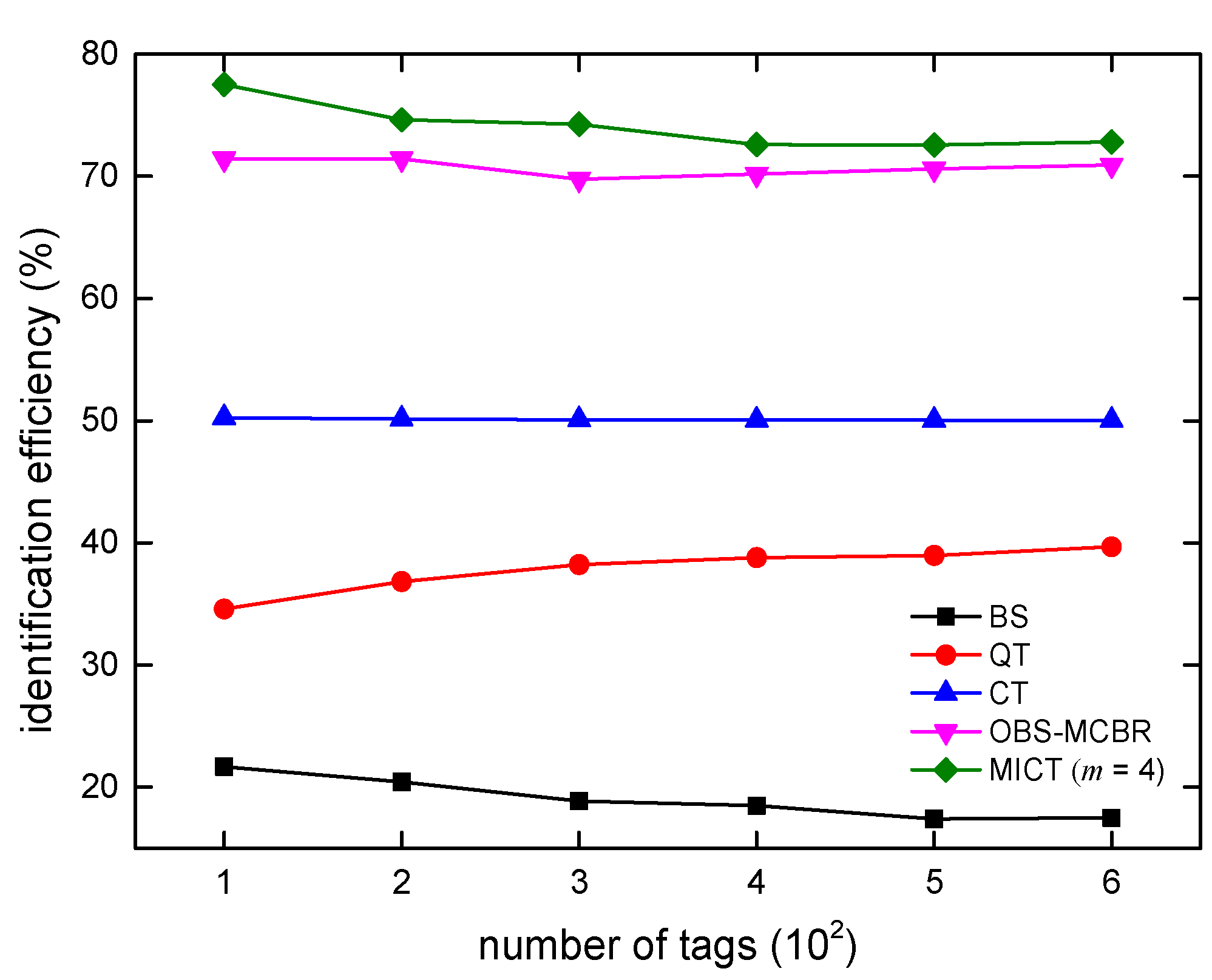
5.3.3. Identification Efficiency Analysis

The identification efficiency is also called the throughput, which refers to the ratio of the number of tags identified to the query cycles required to complete the identification of these tags. Let EMICT(n) be the identification efficiency of MICT algorithm. The identification efficiency of MICT algorithm can be obtained as follows:
E M I C T ( n ) = n T ( n )
Substituting Equation (12) into the above equation yields the following equation:
E M I C T ( n ) = n ( 2 m 1 ) m = 2 2 m [ ( m n 1 ) / ( m 1 ) ]
Table 7 lists the value of the identification efficiency under different values of m when the number of tags varies from 100 to 5000.
It can be seen from Table 7 that the minimum identification efficiency of the MICT algorithm is maintained at more than 60%, and when the value of m is greater than 3, the identification efficiency is more than 80%. If the value of m is greater than 6, the length after encoding will be greater than the length of the tags. This increases the amount of data transmitted. Therefore, the value of m varies from 2 to 6. From the theoretical analysis in Section 5.3.1, we can see that the time complexity of MICT algorithm decreases with the increase in m. From the definition of identification efficiency, it can be seen that when the number of tags is certain, the lower the time complexity and the higher the identification efficiency. So, from the theoretical analysis, we can see that when m = 6, the MICT algorithm achieves the optimal identification efficiency. As the number of tags increases, the identification efficiency is stable around 93%, even if the number of tags reaches tens of thousands.

5.3.4. Reader-Side Memory Complexity Analysis

Reader-side memory complexity refers to the number of bits of binary data that the reader the reader needs to store during RFID tag identification. Taking the CT algorithm and the proposed MICT algorithm as examples, the memory complexity of the reader side is analyzed as follows.
Let S(n) be the reader-side memory complexity. As described in Section 5.3.1 and Section 5.3.2, n represents the number of identified tags, lID is the number of identified tags, lcom is the length of the instruction sent by the reader, and lpre,i is the length of the query prefix in the ith cycle.
The CT algorithm uses a stack to store the newly generated prefix in the tag identification process and the reader sends the prefix and waits for the tag’s response. Using SCT(n) to represent the reader-side memory complexity of CT algorithm, it can be expressed as in Equation (23):
S C T ( n ) = l c o m + i = 1 T ( n ) l p r e , i
where T(n) is the time complexity of the CT algorithm and the value of lcom is fixed. According to the query and response process of CT algorithm, it is necessary for the reader to update the value of the query prefix according to the decoding status in each query cycle. Therefore, in different query-response periods, the value of lpre,i will constantly change, and its range is 0 l p r e , i < m .
In the MICT algorithm, set up two arrays, one for recording the collision, the other to store the query prefix—as long as the ID of the tag to determine the length of the array space is also determined. Using SMICT(n) to represent the reader-side complexity of CT algorithm, it can be expressed as in Equation (24):
S M I C T ( n ) = l c o m + 2 l I D .
When the number of tags is large, the value of i = 1 T ( n ) l p r e , i is much larger than the value of 2 l I D , so in the case of large-scale tag identification, the MICT algorithm is more dominant than the CT algorithm in the memory complexity of the reader-side. The Table 8 lists reader-side memory complexity for several existing tree-based anti-collision algorithms.
It can be seen from the Table 8 that the reader-side memory complexity of the BS, QT, and CT algorithms is influenced by both the number of tags and the length of the tag. In the MICT algorithm, the memory complexity of the reader is not affected by the time complexity. Therefore, compared with stack storage schemes, an array storage scheme can effectively reduce the amount of data stored at the reader side, and the amount of data does not increase with the increase in number of tags.

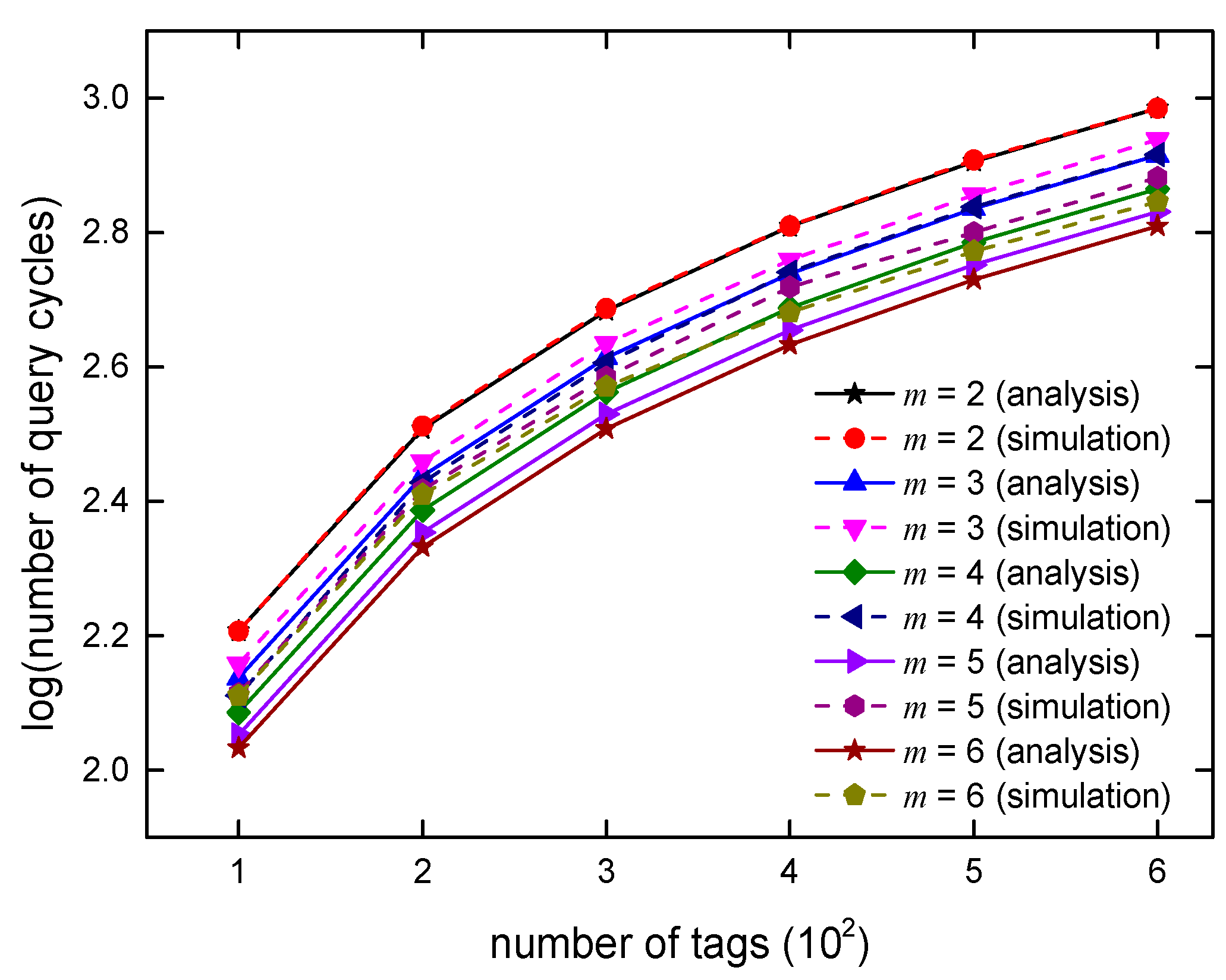
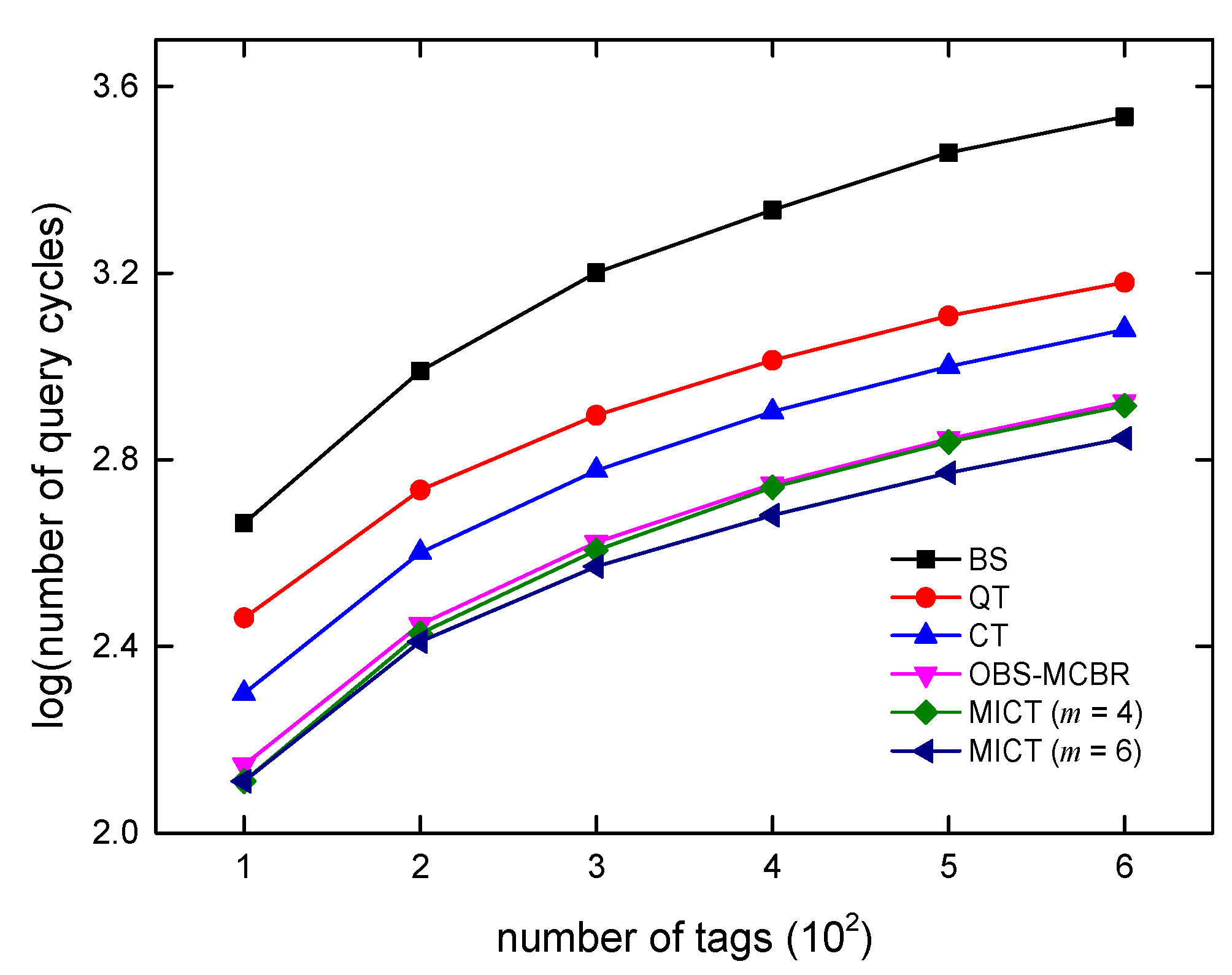
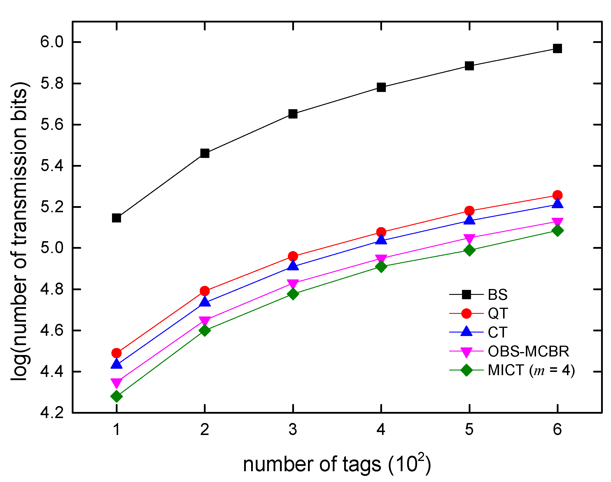
6. Algorithm Simulations and Analysis

The MICT algorithm and several other typical tree anti-collision algorithms are simulated using MATLAB software. The testing simulates the identification of one reader and multiple tags. The number of labels range from 100 to 600. The step length is 100, and tags’ IDs are 96 bits. Each data point in Figure 7, Figure 8, Figure 9, Figure 10, Figure 11 and Figure 12 is the average value obtained after 50 rounds experiment. The paper obtains the m value of the MICT algorithm with the best performance. Furthermore, the experimental results of MICT algorithm are compared to the theoretical value. Finally, the proposed algorithm is compared to existing classical tree anti-collision algorithms with the time complexity, communication complexity, and recognition efficiency.
It can be seen from Figure 7 that the maximum number of query cycles is required when m is equal to 2, that is, the time complexity is the largest. With the increase in m, the time complexity is obviously reduced. When m = 6, the number of queries required in the identification process is the lowest.
The complexity of communication reflects the energy consumption of the system. The less data transferred between the reader and the tags, the lower the energy consumption of the system. The MICT algorithm uses the m-M encoding scheme and the length of the tag is 96 bits. It can be seen from Figure 8 that the communication complexity is the largest when m = 6. When m = 4, the communication complexity is the smallest, and with the increasing of m, the communication complexity gradually increases, which is related to the coding program.
Figure 9 shows the number of query cycles in the experimental simulation compared to the theoretical analysis values. When m = 2, it can be seen from the Figure 9 that the two lines almost coincide, which indicates that the experimental values are highly consistent with the theoretical values; the average deviation is just 0.6%. Due to the unpredictable specific collision of different tags, the theoretical derivation of time complexity can only be expressed as an average value. In the time complexity expression given in Section 5.3.1, the set of values of m is C{2,3,... 2m}; when the value of m increases from 2 to 6, the number of elements in the set increases exponentially. At the same time, the actual collision is affected by the m value relatively small, from updating the 2-bit prefix to the 6-bit prefix, so the error of the actual experimental results obtained with the theoretical analysis value increases with m. It is for this reason that as the value of m increases, the deviation between the experimental values and the theoretical values is different. When m = 4, the average deviation of the experimental values and the theoretical values is about 10%, and when m = 6, the average deviation is about 13%. When m increases from 2 to 6, the average error between the experimental and theoretical values is about 8%.
Figure 10 and Figure 12 demonstrate the comparison of MICT algorithms with the BS, QT, CT, and OBS-MCBR algorithms in terms of time complexity, communication complexity, and identification efficiency. It can be seen from the Figure 10 that the BS algorithm needs the most query cycles when the number of tags increases, and the other four algorithms are better than the BS algorithm. The MICT algorithm performs best when m = 6. When identifying 500 tags, the BS algorithm needs more than 2800 query cycles, the QT algorithm needs more than 1200 queries, the CT algorithm needs about 1000 times, the OBS-MCBR algorithm needs about 700 query cycles, and the proposed MICT algorithm needs about 600 query cycles. MICT algorithm’s time complexity is reduced by 53%, 38%, and 12%, respectively, compared to the QT, CT, and OBS-MCBR algorithms. When m = 4, the performance of the MICT algorithm in terms of time complexity is equivalent to that of the OBS-MCBR algorithm. In terms of the amount of data transmitted, the performance of the BS algorithm is the worst, and the performance of the MICT algorithm is the best when m = 4. When identifying 500 tags, the QT algorithm needs more than 150,000 bits, the CT algorithm needs more than 130,000 bits, the OBS-MCBR algorithm needs about 110,000 bits, and the proposed MICT algorithm needs 9000 bits. Compared to the QT, CT, and OBS-MCBR algorithms, the communication complexity is reduced by 35%, 27%, and 8%, respectively.
Although the MICT algorithm has the fewest queries when m = 6, the amount of data transmitted is also the largest. The MICT algorithm saves 48 bits on the average amount of data transmitted by each identification tag when m = 4 than when m = 6. For the two aspects (number of query times and amount of communication data), MICT selects m = 4 when identifying the label of the 96 bits. In terms of identification efficiency, the MICT algorithm reaches 74% when m = 4, followed by the OBS-MCBR algorithm, which reaches 72%, and the recognition efficiency of CT algorithm is about 51%. The computational burden of the anti-collision algorithm is related to the number of queries and the amount of communication data between readers and tags. When the number of queries and the amount of communication data is reduced, the computational burden of the algorithm will decrease accordingly. From the above experimental results, it can be seen that, compared to existing algorithms, the MICT algorithm reduces the number of queries and the amount of communication data. Therefore, the computational burden of the MICT algorithm is the lowest among these algorithms.

7. Conclusions

Based on the CT algorithm, an anti-collision algorithm with multi-bit identification is proposed using the array storage scheme and coding scheme. The proposed algorithm extends the length of the prefix of one bit in the traditional tree-based algorithm to several bits in each query cycle. Through theoretical analysis and experimental simulation, it is concluded that the MICT algorithm has obvious advantages in terms of time and communication complexity compared to several existing algorithms.

Acknowledgments

This work was partially supported by Science & Technology Program of Shaanxi Province under projects 2017GY-196 and 2015KTCXSF-10-11, and the Opening Fund of State and Local Engineering Laboratory of Advanced Network and Monitoring Control under project GSYSJ2016001.

Author Contributions

Baolong Liu and Xiaohao Su conceived and designed the scheme; Baolong Liu analyzed the efficiency; Xiaohao Su simulated the system; Baolong Liu and Xiaohao Su wrote the paper.

Conflicts of Interest

The authors declare no conflict of interest.

References

  1. He, M.; Horng, S.-J. A fast RFID tag identification algorithm based on counter and stack. Expert Syst. Appl. 2011, 38, 6829–6838. [Google Scholar] [CrossRef]
  2. An, J.; Wu, J.X. Improved RFID binary search anti-collision algorithm. Comput. Eng. Appl. 2009, 45, 229–235. [Google Scholar]
  3. Tsai, S.-C.; Min, Y. Efficient tag reading protocol for large-scale RFID systems with pre-reading. Comput. Commun. 2016, 88, 73–83. [Google Scholar] [CrossRef]
  4. Myung, J.; Lee, W. Tag-splitting: Adaptive collision arbitration protocols for RFID tag identification. IEEE Trans. Parallel Distrib. Syst. 2007, 18, 763–775. [Google Scholar] [CrossRef]
  5. Jung, H. A memory efficient anti-collision protocol to identify memoryless RFID tags. J. Inf. Process. Syst. 2015, 11, 95–103. [Google Scholar]
  6. Mohammed, U.S.; Salah, M. Tag anti-collision algorithm for RFID systems with minimum overhead information in the identification process. Radio Eng. 2011, 20, 61–68. [Google Scholar]
  7. Shin, J.; Jeon, B. Multiple RFID tags identification with M-ary query tree scheme. IEEE Commun. Lett. 2013, 17, 604–607. [Google Scholar] [CrossRef]
  8. Agrawal, T.; Biswas, P.K. An optimized query tree algorithm in RFID inventory tracking-a case study evidence. Int. J. Comput. Sci. 2012, 9, 85–93. [Google Scholar]
  9. Kim, S.; Kim, Y. A tag prediction anti-collision algorithm using extra bits for RFID tag identification. Int. J. Ad Hoc Ubiquitous Comput. 2012, 10, 164–174. [Google Scholar] [CrossRef]
  10. Jiao, C.-H.; Wang, K.-R. Multi-branch query tree protocol for solving RFID tag collision problem. J. China Univ. Posts Telecommun. 2008, 15, 51–54. [Google Scholar] [CrossRef]
  11. Jia, X.L.; Feng, Q.Y. An efficient anti-collision protocol for RFID tag identification. IEEE Commun. Lett. 2010, 14, 1014–1016. [Google Scholar] [CrossRef]
  12. Safa, H.; El-Hajj, W. A distributed multi-channel reader anti-collision algorithm for RFID environments. Comput. Commun. 2015, 64, 44–56. [Google Scholar] [CrossRef]
  13. Lai, Y.C.; Hsiao, L.Y. An RFID anti-collision algorithm with dynamic condensation and ordering binary tree. Comput. Commun. 2013, 36, 1754–1767. [Google Scholar] [CrossRef]
  14. Klair, K.; Chin, W. A survey and tutorial of RFID anti-collision protocols. IEEE Commun. Surv. Tutor. 2010, 12, 400–421. [Google Scholar] [CrossRef]
  15. Yan, X.Q.; Liu, Y. A memoryless binary query tree based Successive Scheme for passive RFID tag collision resolution. Inf. Fusion 2015, 22, 26–38. [Google Scholar] [CrossRef]
  16. Guo, H.B.; He, C. PSR: A novel high-efficiency and easy-to-implement parallel algorithm for anti-collision in RFID systems. IEEE Trans. Ind. Inform. 2016, 12, 1134–1143. [Google Scholar] [CrossRef]
  17. Zhang, Y.; Yang, F. An anti-collision algorithm for RFID-based robots based on dynamic grouping binary trees. Comput. Electr. Eng. 2018, in press. [Google Scholar] [CrossRef]
  18. Ma, Y.M.; Jin, D. Anti-collision algorithm based on Multi-threaded RFID lock position. Int. J. Hybrid Inf. Technol. 2013, 6, 95–102. [Google Scholar]
  19. Landaluce, H.; Perallos, A. Managing the number of tag bits transmitted in a bit-tracking RFID collision resolution protocol. Sensors 2014, 14, 1010–1027. [Google Scholar] [CrossRef] [PubMed]
  20. Jung, Y.; Kim, D. Optimized binary search with multiple collision bits resolution anti-collision algorithm for efficient RFID tag identification. IEICE Trans. Fundam. Electron. Commun. Comput. Sci. 2016, 99, 1494–1498. [Google Scholar] [CrossRef]
  21. Wang, Y.H.; Liu, Y. A multi-bit identification protocol for RFID tag reading. IEEE Sens. J. 2013, 13, 3527–3535. [Google Scholar] [CrossRef]
  22. Su, X.H.; Liu, B.L. An investigation on tree-based tags anti-collision algorithms in RFID. In Proceedings of the International Conference on Computer Network, Electronic and Automation (ICCNEA), Xi’an, China, 23–25 September 2017; pp. 5–11. [Google Scholar]
Figure 1. Tag-tag collision diagram.
Information 09 00063 g001
Figure 2. Tag-reader collision diagram.
Information 09 00063 g002
Figure 3. Reader-reader collision diagram.
Information 09 00063 g003
Figure 4. Array storage diagram.
Information 09 00063 g004
Figure 5. Identification process based on coding.
Information 09 00063 g005
Figure 6. Algorithm flow chart of reader side.
Information 09 00063 g006
Figure 7. Comparison of query cycles.
Information 09 00063 g007
Figure 8. Comparison of data transmission.
Information 09 00063 g008
Figure 9. Comparison of simulation and analysis values.
Information 09 00063 g009
Figure 10. Comparison of query cycles.
Information 09 00063 g010
Figure 11. Comparison of data transmission.
Information 09 00063 g011
Figure 12. Comparison of the identification efficiency.
Information 09 00063 g012
Table 1. The execution of the array scheme.
Query CyclesPrefixProbe_Array[0…7] Reader’s Decoding StatusResponse TagsIdentification Status
01234567
1ε10000000110100100011011010101101collision
×-------
20100000000110110Tag B is identified
00110110
310100000010100100101101collision
1×------
41001000000101101Tag C is identified
10101101
51100000000010010Tag A is identified
11010010
Table 2. Storage scheme comparison.
Number of TagsStack (bits)Array (bits)
1006.460.96
2007.550.48
3008.120.32
4008.540.24
5008.820.19
6009.150.16
Table 3. m-M code (m = 2).
Prefix Bits (m = 2)Encoded Bits (M = 4)
000001
010010
100100
111000
Table 4. m-M code (m = 3).
Prefix Bits (m = 3)Encoded Bits (M = 8)
00000000001
00100000010
01000000100
01100001000
10000010000
10100100000
11001000000
11110000000
Table 5. The code storage of reader-side (m = 2).
Str[0]00
Str[1]01
Str[2]10
Str[3]11
Table 6. MICT algorithm identification table.
Query CyclesPrefixProbe_Array[0…7] Decoding StateResponse TagsStack
1ε04000000000101101011111111010100110111001011××××××0,1,2,3
××
20003030000000101101011111111×××××10,2,3,1,2,3
00××
3000003020000Tag A is identified2,3,1,2,3
00000101
4001003010000Tag B is identified3,1,2,3
00101011
5001103000000Tag C is identified1,2,3
00111111
60102000000Tag D is identified2,3
01010100
71001000000Tag E is identified3
10110111
81100000000Tag F is identifiedNULL
11001011
Table 7. The theoretical value of identification efficiency.
The Value of mNumber of Tags
10050020005000
262.11%62.11%62.07%62.07%
372.99%72.99%72.99%72.97%
481.97%81.97%81.90%81.89%
588.50%88.50%88.50%88.51%
693.46%93.11%93.02%93.02%
Table 8. Comparison of the reader-side memory complexity.
AlgorithmReader-Side Memory Complexity
BS l c o m + [ n + log 2 ( n ! ) ] l I D [22]
QT l c o m + i = 1 n ( l I D + 2 lg n ) l p r e , i (the worst situation) [22]
CT l c o m + i = 1 2 n 1 l p r e , i
MICT l c o m + 2 l I D

