Article

Sliding-Mode Speed Control of PMSM with Fuzzy-Logic Chattering Minimization—Design and Implementation

by
Fadil Hicham
1,*,
Driss Yousfi
1,
Aite Driss Youness
2,
Elhafyani Mohamed Larbi
1 and
Nasrudin Abd Rahim
3
1
National School of Applied Sciences, Mohammed First University, Oujda BP 669, 60000, Morocco
2
National School of Applied Sciences, Cadi Ayyad University, Marrakech BP 575, 40000, Morocco
3
UMPEDAC, University of Malaya Power Energy Dedicated Advanced Centre, Kuala Lumpur 59990, Malaysia
*
Author to whom correspondence should be addressed.
Information 2015, 6(3), 432-442; https://doi.org/10.3390/info6030432
Submission received: 15 June 2015 / Revised: 15 July 2015 / Accepted: 16 July 2015 / Published: 28 July 2015
(This article belongs to the Special Issue Selected Papers from MedICT 2015)

Abstract

:
In this paper a Sliding Mode Control scheme (SMC) applied to the Permanent Magnet Synchronous Motor (PMSM) speed control is designed and improved. A Fuzzy logic algorithm is added to mitigate chattering caused by discontinuous term in steady states, and to ensure good performances of the controller in transient states. The proposed Fuzzy-SMC performance is tested in simulation and experimental results are obtained using eZdsp F28335.

1. Introduction

Numerical PMSM control drives are extremely improved by the development of calculators, especially digital signal processors (DSPs). Consequently, nonlinear control methods are introduced to improve control performances for systems with different undesirable disturbances and uncertainties i.e., adaptive control [1], robust control [2], direct torque control [3], intelligent control [4] and sliding mode control (SMC) [5]. This last technique is applied in many control fields [6,7] in addition to sensorless control.
The SMC is very attractive, and it has been recommended for many applications [8,9], compared to a conventional PI controller which is very sensitive to parameter uncertainty and variation. In [8] a sliding mode control is used to obtain a high-accuracy positioning of a six-phase induction machine in both healthy and faulted modes. In [9] an adaptive non-singular terminal sliding mode tracking control is designed to provide faster convergence and higher precision control for robotic systems. Moreover, the SMC can be combined with other non-linear approaches to ensure stability of multivariable complex system control [10].
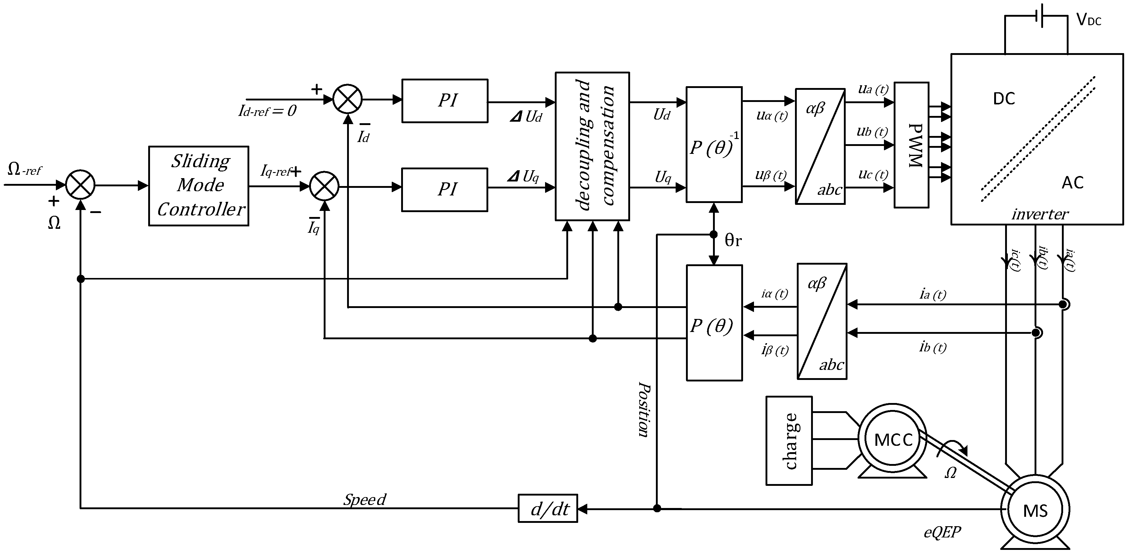
Nevertheless, the robustness of the SMC comes at the expense of some drawbacks such as the well-known chattering phenomenon induced at steady state due to the discontinuous term in the control law. Furthermore, once implemented in PMSM speed control, associated with conventional vector control (Figure 1), it leads to a sonorous vibration and perturbs the current control loop. Subsequently, the power losses and the torque ripple increase considerably. Various methods have been proposed to overcome the charting problems, such as: reaching law method [11,12], complementary sliding-mode method [13] and high-order sliding-mode method [14,15]. The reaching law depends directly on the reaching process, since chattering is caused by the non-ideal sliding on the SM surface at the end of the reaching phase [16,17]. By making the discontinuous gain a function of the sliding-mode surface, the chattering is reduced in [12]. In [18], a novel Exponential Law based Sliding Mode Control is assumed to construct the speed and current integrated controller.
Figure 1. Overall block diagram of the proposed control system.
Information 06 00432 g001
The main idea of those works is to smooth the control action across the sliding surface. They suffer, however, from a number of limitations and shortcomings such as difficulty of experimental implementation and design complexity. Additionally, the response time and the robustness of the controller near the sliding surface are degraded in the aforementioned research.
In this paper, the PI speed controller is replaced by SM controller to remove the machine parameters dependency and external disturbance effects. The controller associated problems are investigated and eliminated as well. The large gain of the discontinuous law, used in first order SMC, is the key feature to make the SM controller tolerant to model parameter uncertainty. It also makes the system response and the load disturbance rejection faster. These benefits are reached with the loss of smooth torque. Hence, a Fuzzy logic algorithm is introduced to adjust the weight of the SM gain, in such a way, it can be taken large than standard value during transient period to conserve the SMC performance.
In order to minimise the current chattering in steady state, the Fuzzy algorithm is designed to attenuate the discontinuous term in that operating condition. Consequently, less torque ripple and vibration are generated.
Some basic theoretical development of SMC and PMSM modelling are presented in Section 2 and Section 3, and the success of the proposed SMC is verified by simulation and experimentation in Section 4.

2. Permanent Magnet Synchronous Motor Model

In order to adjust the PMSM speed, a model of this machine with an average complexity level is required. Indeed, the controllers in the control loop tolerate several modelling simplifications, such as perfect sinusoidal distribution of stator winding. In addition, the produced magneto-motive-forces and the magnitude flux linkage through the stator winding are sinusoidal.
So, the electrical model of the PMSM in the rotating reference frame ( a b c ) can be written as the following [19]:
[ u s ( t ) ] a b c = R [ i s ( t ) ] a b c + d [ ψ s ( t ) ] a b c / d t
where [ u s ( t ) ] a b c is the stator voltage vector, [ i s ( t ) ] a b c is the stator current vector, and [ ψ s ( t ) ] a b c is the stator flux vector.
However, the flux ψ s ( t ) is a result of stator windings and rotor permanent magnet flux. It can be presented in the rotating frame linked to the stator as:
[ ψ s ( t ) ] a b c = [ L M M M L M M M L ] [ i s ( t ) ] a b c + Ψ m [ cos ( θ r ) cos ( θ r 2 π / 3 ) cos ( θ r + 2 π / 3 ) ]
where L and M are respectively, the self-inductance of the stator winding and the mutual-inductance between the windings. Ψm is the maximal amplitude of the permanent magnet flux and θr is the electrical rotor position.
As the synchronous motor investigated in this paper is a surface mounted permanent magnet motive, the quantities L and M are constants. Consequently, the notation L s = L M can be made to simplify modelling.
Several control methods are developed in the literature such as DTC and vector control techniques. In this work, a PMSM drive is designed using a vector control technique associated with combined PI and sliding mode controllers.
To achieve the vector control, the Park transformations from/to the rotating reference frame linked to the rotor are required. By applying Park transforms presented in [20] to Equations (1) and (2), the state-space equations of the dynamic electrical and mechanical systems can be derived [20]:
{ d d t [ i d i q Ω ] = [ R / L s P Ω 0 P Ω R / L s P Ψ m / L s 0 3 P Ψ m / 2 J f r / J ] [ i d i q Ω ] + [ 1 / L s 0 0 0 1 / L s 0 0 0 1 / J ] [ u d u q T c h ] Ω = [ 0 0 1 ] [ i d i d Ω ] t
where ud, uq are the stator d- and q-axes voltages; id, iq are the stator d- and q-axes currents; R is the stator resistance; Ω is the rotor angular velocity, P is pairs pole number; Tch is the load torque; fr is the viscous friction coefficient and J is the inertia moment.
It is noticed from Equation (3) that the model in the rotating reference frame is coupled, and it contains nonlinear terms. Then, to achieve the vector control, the control loop presented in Figure 1 is opted. It consists of a decoupling block, a model linearization and additionally two control loops.

3. Sliding Mode Controller Design and Chattering Minimization

For speed control, two control loops have been used as mentioned previously. The inner control loop is based on PI controller and is utilized to regulate the direct and quadratic currents. To operate in the maximal torque the direct current is controlled to be zero. Indeed, the torque becomes linked to the quadratic current. On the other hand, the speed could be controlled directly by this quadratic current, which is necessarily the output of the outer control loop. In our case, the controller is a Fuzzy-SM controller.
The SMC is a nonlinear technique, insensitive to motor parameters variation and load change. However, its output law is noisy in the steady state. Basics of SMC design are introduced in the next section, followed by the proposed Fuzzy logic algorithm used for chattering minimization.

3.1. The Basic Sliding Mode Controller Design
SMC has been employed to numerous applications investigated in literatures [6,7] and has been applied to several systems with various behaviours. However, to design SMC the system must be represented as state-space equations to simplify the choice of the sliding-mode surface and to construct the output control law as well. Those states are briefly explained in the following.
The SM controller is designed for Single-Input Single-Output linear systems, which have the following dynamic behaviour
{ x ˙ 1 = x 2 x ˙ n = i = 1 n a i x i + b u y = x 1
where x = [ x 1 x n ] T are system states, n is the system order and u is the input.
The sliding mode surface that can guarantee the asymptotic stability for such systems has been presented in [21,22] as follows:
S = i = 1 n c i ( y y d ) i 1  and   c n = 1
In order to simplify the SMC output calculation, an ideal sliding is assumed. In addition, the system trajectory is forced toward the sliding-mode surface, furthermore the reaching law is chosen as:
S ˙ = k sgn ( S )
From the Equations (3), (5) and (6), the controller output law can be expressed as in the Equation (7). Where the load torque was estimated from the speed and the PMSM quadratic control current iq based on the Equation (3) at steady state.
i q * = 2 ( T c h * + f r Ω k sgn ( S ) ) / 3 P Ψ m
T c h * = 3 P Ψ m i q / 2 f r Ω
It seems from Equation (7) that the control output law contains the discontinuous term 2 k sign ( S ) / 3 P Ψ m . This expression ensures the stability and the sliding mode surface attraction. However, it generates torque ripples depending on the value of k, even at steady state operation. In order to attenuate this gain effect, a Fuzzy logic algorithm is adopted.
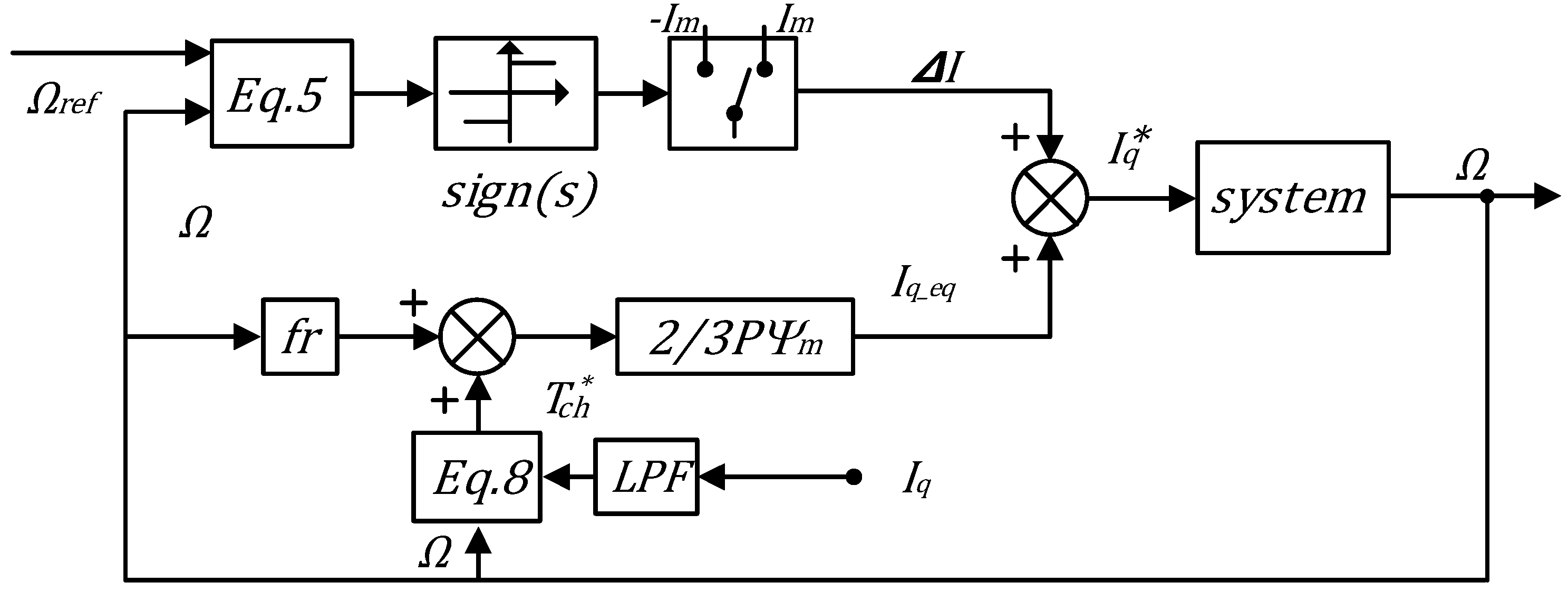
The SM controller scheme is presented in Figure 2, in which the discontinuous term is presented by ΔI and the equivalent control law is donated by Id-eq.
Figure 2. Sliding Mode Controller scheme.
Information 06 00432 g002

3.2. Chattering Minimization Using Fuzzy Logic Algorithm

The chattering minimization is achieved based on the calculation of a mitigation term. The concept is to multiply the discontinuous component by the mitigation term. To calculate this term, an algorithm is programmed using Sugeno Fuzzy inference technique. The Fuzzy block has two inputs, i.e., the SM surface S and the measured speed Ω. The proposed scheme together with the resulting control surface, obtained by plotting the inferred control action, is illustrated in Figure 3.
The control surface shows that the Fuzzy programmed algorithm intervenes to modify the discontinuous term amplitude appropriately. In order not to disturb the transient state, this amplitude is reduced when the system is close to the SM surface and not affected far from this surface. However, this action of the Fuzzy block is weakened by the second input at standstill and low speed to overcome static frictions.
Figure 3. The proposed SMC scheme and the fuzzy logic control surface.
Information 06 00432 g003
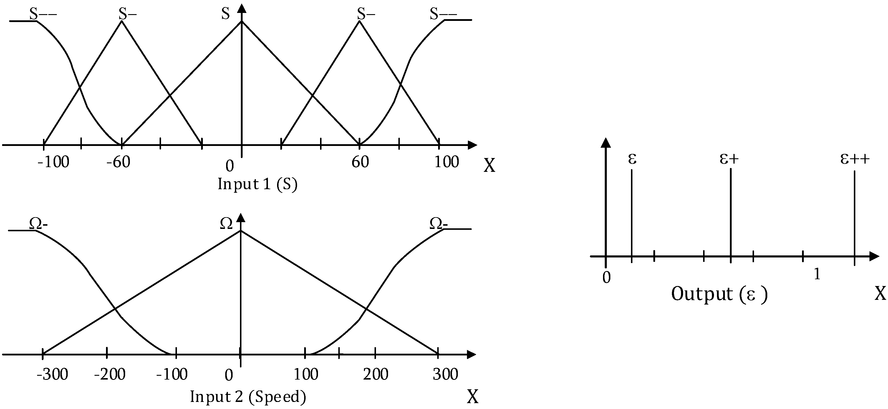
To accomplish the required Fuzzy logic operations, three Fuzzy sets are used to describe the low speed range and five sets are exploited to present the distance between the operating point and SM surface. Three additional Fuzzy sets are introduced to define the appropriate mitigation value of the SM discontinuous term as shown in Figure 4. Furthermore, 15 input/output rules are established and arranged according to Table 1. In this way, the resulting Fuzzy logic algorithm ensure good chattering minimization in the steady stat without affecting the controller performance in transient operations.
Figure 4. The proposed inputs and output sets.
Information 06 00432 g004
Table 1. Rules base of the fuzzy controller.
InputsS--S-S0S+S++
Ω-ε++ε+εε+ε++
ε++ε+εε+ε++
Ω+ε++ε+εε+ε++

4. Simulation and Experimental Results

The proposed algorithm was validated by simulation using Matlab/Simulink® (Version 2012a) linked to Plecs. The same algorithm was implemented using a test bench including 80W PMSM as shown in Figure 5. The machine parameters and PWM configuration requirement are presented in Table 2. To operate near nominal operating point, the PMSM was loaded by DC generator supplying a resistive bank. An incremental encoder was used to measure the speed and rotor position (2000 resolution). An eZdspF28335 board with 10 kHz sampling frequency was used. The control programmes are designed using rapid prototyping system in Matlab/Simulink® environment. A Matlab/GUI real time interface was developed to display and make results record easily [23]. This experimental environment is illustrated in Figure 5.
Table 2. Simulation and experiment parameters.
ComponentsValuesComponentsValues
Rated powerP = 80 WPole pairs4
DC-voltage24 VViscous frictionfr = 0.04 10-3 Kgm2
Rated speed4000 rpmRotation inertiaJ = 0.5 10-3 Nm/rad
Resistance and inductanceR = 0.43 Ω, L = 1.35 mHSamplingfs = 10 kHz
Rated torque0.19 NmPWM frequencyFPWM = 10 kHz
Figure 5. The experimental setup including the 80 W PMSM and power inverter.
Information 06 00432 g005

4.1. Simulation Results and Discussion
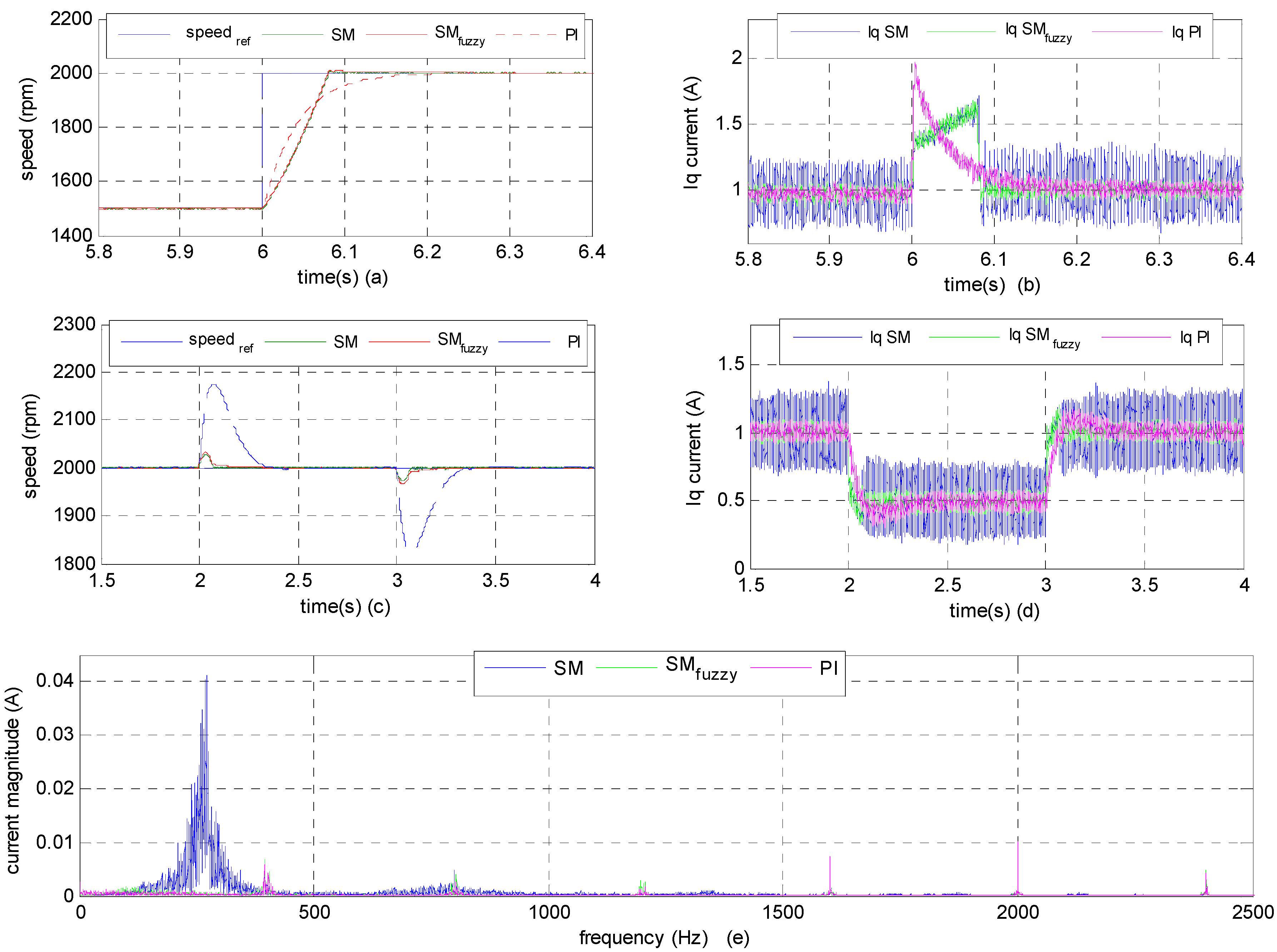
The proposed Fuzzy-SM and SM controllers were tested by simulation in different operating conditions, and they had been compared to a traditional PI controller. The PI controller gains were obtained using pole compensation method providing the same response time as Fuzzy-SM and SM controllers i.e., K P ω = 0.002 , T i ω = 1.08 . In the first simulation test, the machine is operating under the same load torque for all of the three controllers. Also, the current PI controller gains were set identical as K P i d q = 0.9 , T i i d q = 0.0031 . A speed step reference is applied from 1500 rpm to 2000 rpm, and the speed response is shown in Figure 6a. These results demonstrate that the Fuzzy-SM and SM controllers have the same rising time compared to the PI.
Furthermore, when the same load disturbance is added and removed at 2000 rpm, it can be seen clearly from Figure 6c that the maximum fluctuation of the speed comes when the PI controller is adopted. Conversely, the advanced SM and Fuzzy-SM controllers are able to perform well, offering slight speed tracking errors, as well as short recovering time against disturbance.
Figure 6. Simulation results. (a) Speed and (b) current following a reference speed change; (c) Speed and (d) current in presence of load disturbance; (e) Frequency analyses of quadratic current. This simulation was performed with SMC, Fuzzy-SMC and PI controller.
Information 06 00432 g006
It is apparent that the motor can recover to a constant speed quickly by using both controllers: Fuzzy-SM and SM controller. However, the weakness of the SMC is visible in the resulting noisy quadratic current supplying the PMSM, as shown in Figure 6b,d. Subsequently, the generated torque induces intense ripples and vibrations. The large current chattering in the conventional sliding-mode controller arises from the selection of large control gains.
This issue is surmounted by the Fuzzy-SMC that acts like SMC in transient state and like PI controller in steady state. One can observe, throughout Figure 6b,d, that the proposed Fuzzy-SM controller has good load disturbance rejection without producing current chattering phenomenon.
Those conclusions are confirmed by an FFT analysis of the quadratic current ripple at 2000 rpm, which is presented in Figure 6e. The results demonstrate that the quadratic current noise is considerably attenuated, when the proposed Fuzzy-SMC is used, compared to the standard SMC.

4.2. Implementation and Experimental Results
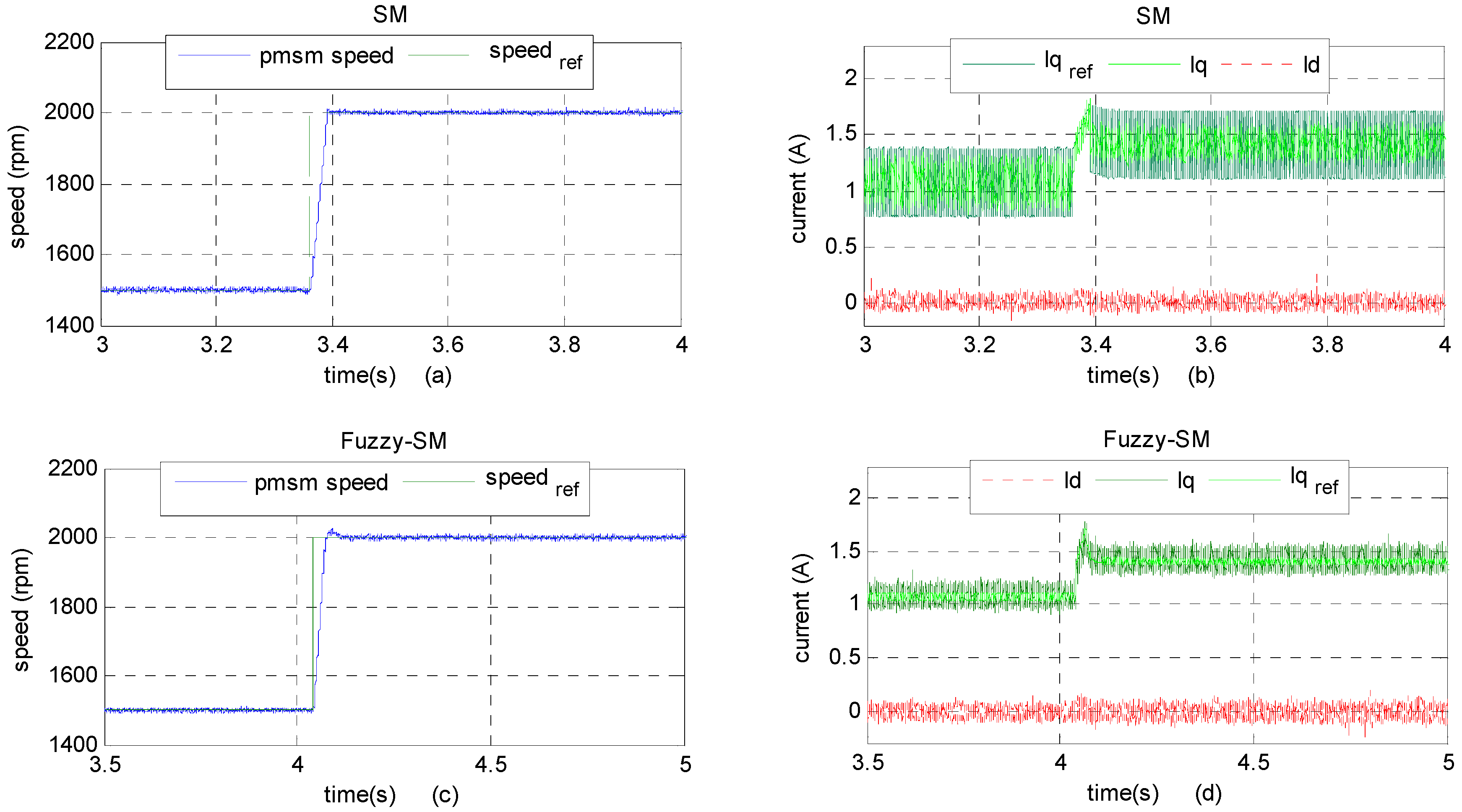
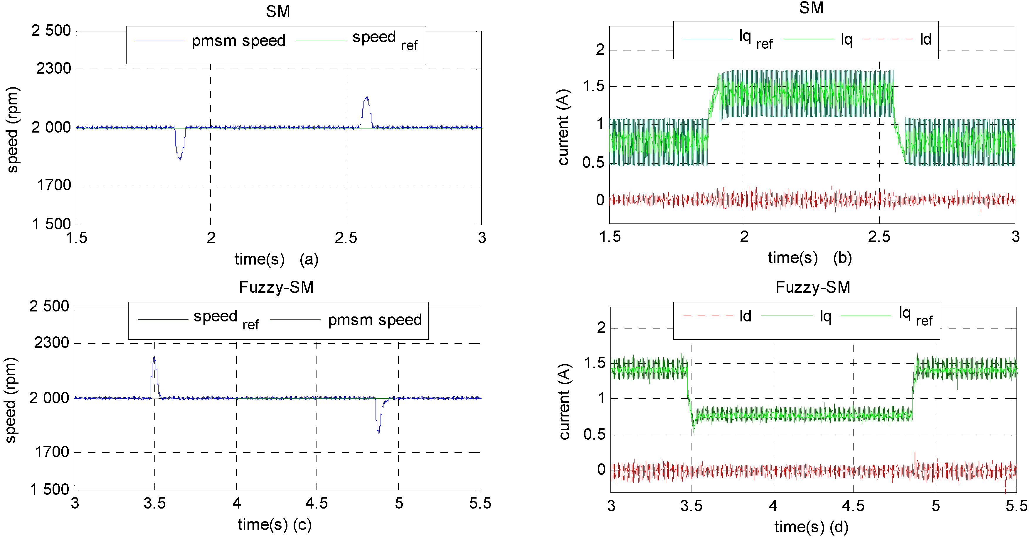
To experimentally evaluate the robustness of Fuzzy-SMC and to compare it with SMC, the same controller parameters used in simulation are used in practice. In the first experiment given in Figure 7, it can be seen that during a speed change from 1500 rpm to 2000 rpm, the speed response and steady state error are controlled. In addition, a load disturbance test is accomplished at 2000 rpm; 10% of load is added and removed and the results are shown in Figure 8. From speed curves of Figure 8a,c, it seems that SMC and Fuzzy-SMC have the same control performances. However, as mentioned in simulation, the PMSM reference and actual quadratic currents present more ripples (Figure 7b and Figure 8b). With Fuzzy-SMC the current becomes smoother as demonstrated by Figure 7d and Figure 8d.
Figure 7. Experimental results of the proposed Fuzzy-SMC and SMC at the variation of speed. (a), (c), (b) and (d) speeds, Id and Iq when SMC or Fuzzy-SMC is used respectively.
Information 06 00432 g007
Figure 8. Experimental results of load disturbance at 2000 rpm. (a,c) SMC and Fuzzy-SMC speed; (b,d) direct, quadratic and reference currents for the developed methods.
Information 06 00432 g008

5. Conclusions

The important feature required in PMSM speed control is less sensitivity to mechanical motor parameters and load variation. Those advantages are ensured with the developed association of SM controller and Fuzzy logic algorithm used to attenuate the current chattering. First, an SM controller is designed using the mechanical PMSM equations, and the load torque is estimated using motor quadrature current and speed. Moreover, the SM discontinues term effects that manifest in current chattering and torque oscillation, are eliminated using a fuzzy logic algorithm.
The effectiveness of the combined Fuzzy-SM Controller is validated through a series of simulation and experimental tests. The presented method is also compared to SM and conventional PI controllers. The results demonstrate that the system transient response, in closed loop with Fuzzy-SMC, is as good as an SMC. Furthermore, at the steady state, the current as well as the torque are enhanced when the proposed method is used. Indeed, the current disturbances encountered in common SMC are suppressed because the reference current chattering are avoided by the Fuzzy logic algorithm.

Author Contributions

Fadil Hicham initiated the idea of the work. Ait Driss Youness conducted the literature review. Driss Yousfi and Mohamed Larbi Elhafyani prepared the experimental test bench. Abd Rahim Nasrudin supervised the work. All authors have read and approved the final manuscript.

Conflicts of Interest

The authors declare no conflict of interest.

References

  1. Abed, K. Techniques De Commande Avancees Appliquees Aux Machines De Type Asynchrone. Ph.D. Thesis, University Mentouri of Constantine, Constantine, Algeria, 22 Junuary 2010. [Google Scholar]
  2. Hsien, T.L.; Sun, Y.Y.; Tsai, M.C. H control for a sensorless permanent-magnet synchronous drive. In Proceedings of the Power Conversion Conference, Yokohama, Japan, 19–21 April 1993.
  3. Foo, G.H.B.; Rahman, M.F. Direct torque control of an IPM synchronous motor drive at very low speed using a sliding-mode stator flux observer. IEEE Trans. Power Electron. 2010, 25, 933–942. [Google Scholar] [CrossRef]
  4. Casey, B.B.; Azizur Rahman, M. Intelligent Speed Control of Interior Permanent Magnet Motor Drives Using a Single Untrained Artificial Neuron. IEEE Trans. Ind. Appl. 2013, 49, 1836–1843. [Google Scholar]
  5. Fnaiech, M.A.; Betin, F.; Capolino, G.A.; Fnaiech, F. Fuzzy logic and sliding-mode controls applied to six-phase induction machine with open phases. IEEE Trans. Ind. Electron. 2010, 57, 354–364. [Google Scholar] [CrossRef]
  6. Wang, L.; Chai, T.; Zhai, L. Neural-network-based terminal sliding mode control of robotic manipulators including actuator dynamics. IEEE Trans. Ind. Electron. 2009, 56, 3296–3304. [Google Scholar] [CrossRef]
  7. Boubakir, A.; Boudjema, F.; Boubakir, C.; Ikhlef, N. Loi de Commande par Mode de Glissement avec Une Surface de Glissement Non Linéaire Appliquée au Système Hydraulique à Réservoirs Couplés. In Proceedings of the 4th International Conference on Computer Integrated Manufacturing, Algiers, Algeria, 3–4 November 2007.
  8. Fnaiech, M.A.; Betin, F.; Capolino, G.A. Sliding Mode Control applied to the Inner Loop Regulation of a Faulted Six Phase Induction Machine (6PIM). In Proceedings of the Electric Machines and Drives Conference, Miami, FL, USA, 3–6 May 2009; pp. 1305–1310.
  9. Lin, C.K. Nonsingular terminal sliding mode control of robot manipulators using fuzzy wavelet networks. IEEE Trans. Fuzzy Syst. 2006, 14, 849–859. [Google Scholar] [CrossRef]
  10. Shaocheng, T.; Han-Xiong, L. Fuzzy adaptive sliding-mode control for MIMO nonlinear systems. IEEE Trans. Fuzzy Syst. 2003, 11, 354–360. [Google Scholar] [CrossRef]
  11. Su, T.; Liaw, C.M. Adaptive positioning control for a LPMSM drive based on adapted inverse model and robust disturbance observer. IEEE Trans. Power Electron. 2006, 21, 505–517. [Google Scholar]
  12. Gao, W.; Hung, J.C. Variable structure control of nonlinear systems: A new approach. IEEE Trans. Power Electron. 1993, 40, 45–55. [Google Scholar]
  13. Lin, F.J.; Hwang, J.C.; Chou, P.H.; Hung, Y.C. FPGA-based intelligent-complementary sliding-mode control for PMLSM servo-drive system. IEEE Trans. Power Electron. 2010, 25, 2573–2587. [Google Scholar] [CrossRef]
  14. Zhang, X.G.; Zhao, K.; Sun, L. A PMSM sliding mode control system based on a novel reaching law. In Proceedings of the International Conference on Electrical Machines and Systems, Beijing, China, 20–23 August 2011.
  15. Chiu, J.Y.-C.; Leung, K.K.-S.; Chung, H.S.-H. High-order switching surface in boundary control of inverters. IEEE Trans. Power Electron. 2007, 22, 1753–1765. [Google Scholar] [CrossRef]
  16. Lin, C.-K.; Liu, T.-H.; Wei, M.-Y.; Fu, L.-C.; Hsiao, C.-F. Design and implementation of a chattering-free non-linear sliding-mode controller for interior permanent magnet synchronous drive systems. Electr. Power Appl. 2012, 6, 332–344. [Google Scholar] [CrossRef]
  17. Mohammad, R.S.; Pooria, O.; Mohammad, H.K. Robust control strategy for electrically driven robot manipulators: Adaptive fuzzy sliding mode. Electr. Power Appl. Sci. Meas. Technol. 2015, 9, 322–334. [Google Scholar]
  18. Zhao, K.; Zhang, X.G.; Sun, L.; Cheng, C. Sliding mode control of high-speed PMSM based on precision linearization control. In Proceedings of the Electrical Machines and Systems, Beijing, China, 20–23 August 2011; pp. 1–4.
  19. Fadil, H.; Yousfi, D.; Driss, Y.A.; Nasrudin, A.R. Synchronization techniques benchmarking of grid fault modes in single-phase systems. In Proceedings of the Renewable and Sustainable Energy Conference, Ouarzazate, Morocco, 17–19 October 2014; pp. 191–196.
  20. Li, S.; Zhou, M.; Yu, X. Design and Implementation of Terminal Sliding Mode Control Method for PMSM Speed Regulation System. IEEE Trans. Ind. Inform. 2013, 9, 1879–1891. [Google Scholar] [CrossRef]
  21. Lopez, P.; Nouri, A.S. Théorie Elémentaire et Pratique de la Commande par les Régimes Glissants; Mathématiques & Applications 55; Springer: New York, NY, USA, 2006; pp. 25–113. [Google Scholar]
  22. Bartoszewicz, A. (Ed.) Sliding Mode Control; InTech: Rijeka, Croatia, 2011; pp. 25–109.
  23. Fadil, H.; Yousfi, D.; Elhadiyani, M.L.; Driss, Y.A.; Nasrudin, A.R. Design and Experimental Evaluation of a Fuzzy-PI Controller applied to the PMSM Speed control. In Proceedings of the Mediterranean Green Energy Forum, Marrakech, Morocco, 26–28 March 2015.