
Article

Multi-Agent System-Based Real-Time Implementation of Advanced Energy Management in Hybrid Microgrids

by
Praveen Kumar Reddy Kudumula
1,2,* and
P. Balachennaiah
3
1
Electrical and Electronics Engineering, Government Polytechnic, Vempalli 516329, India
2
Electrical and Electronics Engineering Department, Jawaharlal Nehru Technological University Anantapur, Anantapur 515002, India
3
Electrical and Electronics Engineering Department, Annamacharya University, Rajampet 516126, India
*
Author to whom correspondence should be addressed.
Information 2026, 17(5), 497; https://doi.org/10.3390/info17050497
Submission received: 1 April 2026 / Revised: 1 May 2026 / Accepted: 13 May 2026 / Published: 18 May 2026

Abstract

The growing integration of solar, wind and battery energy storage (BES) of the microgrids (MGs) has increased the necessity of real-time energy management, especially in the multi-microgrid (multi-MG) setting, where the generation and the load change stochastically. This paper presents a Java Agent DEvelopment (JADE)-based Multi-Agent System (MAS) for real-time energy management of a low-voltage hybrid multi-MG system incorporating solar photovoltaic (PV), wind generation, and battery energy storage (BES). The proposed framework’s novelty lies in its physical campus-scale hardware deployment—validated across four operating scenarios (single MG off-grid, single MG on-grid, dual MG off-grid, and dual MG on-grid)—combined with autonomous inter-MG power sharing, which distinguishes it from existing simulation-only MAS-based microgrid studies. The suggested framework facilitates decentralized communication between interconnected MGs and the utility AC grid to facilitate the proper management of power flow, its exchange, and the reliability of the system. The intelligent agents are used to coordinate solar, wind, BES, and load changes in order to adjust to changing demand conditions. The system is physically implemented on a campus rooftop with two 1 kW solar PV arrays and two 1.5 kW wind turbine generators, each paired with a 24 V, 150 Ah battery bank, operating on a 24 V DC bus. Results across 24 h real operational profiles demonstrate effective power balance maintenance, renewable energy maximization, and constraint-compliant battery operation (SOC is bounded within 20–90%). A direct comparison with a conventional centralized JavaScript-based EMS confirms equivalent dispatch accuracy while demonstrating superior scalability, fault tolerance, and modularity of the proposed JADE MAS architecture.

1. Introduction

The increasing electricity demand in the world coupled with the growing concerns about the environment and the decline of conventional fossil fuel has heightened the shift towards renewable energy-based power systems. The hybrid microgrids combining renewable energy sources (RES) like solar photovoltaic (PV) and wind energy and distributed energy storage systems (ESS) have become an effective answer to attain energy efficiency, reliability and sustainability in the grid-connected mode and islanded mode of operation. Microgrids provide a higher level of resilience in the system and less transmission loss and greater use of locally available renewable energy, which makes them especially appropriate in the context of contemporary decentralized power systems [1,2,3]. A hybrid microgrid has been widely studied as a powerful tool towards managing renewable energy generation, power storage and load demand. Various alternative methods of energy management and control have also been proposed to enhance system performance, among them being rule-based, metaheuristic-based, and centralized optimization. A Levy Flight Algorithm (LFA)-optimized hybrid PV-wind microgrid with hydrogen and battery storage was introduced in [4], showing a lower cost of the system and better economic viability than the Particle Swarm optimization (PSO) and Genetic Algorithms (GA) solutions. In the same way, the proposed PSO-driven rule-based demand response framework in [5] was suggested to optimize cost-efficiency and the demand-side flexibility in hybrid microgrids. Further optimization-based energy management schemes, including model predictive control (MPC) were also being studied as they are capable of treating system constraints and multi-time scale goals. In [6], a single-layer move-blocking MPC-based energy management system was suggested to integrate short- and long-term goals in one optimization model and to enhance the economic performance and calculation efficiency. Other important methods are neuro-fuzzy-based islanding detection and power management models [7], adaptive gravity search models of shipboard microgrids [8] and decentralized multi-energy management models with fuzzy optimization and Pareto-based decision-making to minimize the operational costs and carbon emissions [9].
Regardless of these developments, hybrid microgrids remain more complex to operate because of the intermittency of the renewable energy sources, non-deterministic variations in loads, and the coordination needs of various distributed components. Traditional centralized or rule-based control mechanisms tend to lack flexibility, experience excessive communication costs, have a low level of scalability, and are susceptible to a single point of failure. Such constraints greatly limit their practicality when operating in real time especially in systems where renewable penetration is high and interlocked micro grids.
In order to deal with these challenges, smart and decentralized control architectures have gained importance as next-generation microgrid energy management. Multi-Agent Systems (MAS) have become an influential paradigm in this respect in the paradigm of distributed control in microgrids. MAS are made up of several autonomous and intelligent agents who have the ability to sense what is happening around them, make decentralized decisions and collaborate with others in the nearby environment towards the accomplishment of global system goals. Such features influence MAS in the challenging management of the dynamic, uncertain and distributed environment of microgrids powered by renewable energy.
The promising potential of MAS-based energy management frameworks in enhancing the reliability, flexibility and economic performance of microgrids has been realized in recent studies. A MAS-based energy management framework was suggested in [10] where a coordinator agent connects the tertiary and primary control level providing real-time economic dispatch of active and reactive power and enhancing system reliability and operational efficiency. In [11] the authors explored energy management in multi-microgrid (MG) systems with the integration of renewable energy sources (RES) and battery energy storage systems (BESS). Conventional centralized control approaches faced limitations in scalability, flexibility, and real-time adaptability. To address these challenges, agent-based and distributed control strategies were proposed for improved coordination and energy sharing among MGs. In [12], the authors proposed an Industry 4.2 framework for green intelligent manufacturing aimed at improving energy efficiency and reducing carbon emissions. The framework utilized cyber-physical agents for data collection and integrated both energy and carbon management systems. This approach enabled enhanced monitoring and control of manufacturing processes. The results demonstrated significant energy savings and a reduction in carbon emissions.
In [13], the authors proposed an ontology-based energy management system based on MAS to integrate building microgrid environments with renewable energy sources and controllable loads allowing uniform distributed generation and demand response. MAS frameworks are improved by AI, which is used to combine short-term load forecasting with adaptability in grid-connected multi-microgrids [14], and hierarchical MAS structures are also improved by peer-to-peer energy trading [15]. MAS methods built around reinforcement learning enhanced further resilience and dispatch efficiency in the case of uncertainty [16]. JADE based MAS monitoring and control have been tested and validated through practical implementations using MATLAB R2024a, including both simulation and hardware testing [17]. Moreover, smart MAS-based solutions have been demonstrated to be useful to off-grid hybrid home systems [18] and islanded AC- DC microgrids, in which agent-based optimization methods made it possible to reduce costs, manage demand response, and decrease load shedding [19].
Despite the progress outlined above, the existing body of MAS-based microgrid research is characterized by three significant limitations: (i) the vast majority of studies are validated exclusively through software simulation (e.g., MATLAB/Simulink) with little or no physical hardware deployment; (ii) most frameworks address single-microgrid configurations, leaving the more complex problem of real-time coordinated energy management across multiple interconnected microgrids underexplored; and (iii) systematic performance comparison of MAS-based EMS against conventional centralized control under identical real-world operating conditions is rarely reported. These gaps motivate the present work.
Based on these identified gaps, this paper makes the following original contributions, which collectively distinguish it from the existing MAS-microgrid literature as summarized in Table 1 below.
This paper has made several key contributions as summarized below:
  • Design and physical implementation of a real-time, low-voltage hybrid dual microgrid system on a campus rooftop and laboratory, comprising two interconnected microgrids each with solar PV, wind generation, and battery energy storage.
  • Development of a JADE-based multi-agent architecture—encompassing Generation Agents (SA, WA), Battery Agent (BA), Load Agent (LA), Grid Agent (GA), and Control Agent (CA)—for fully decentralized, autonomous energy management with FIPA-compliant ACL inter-agent communication.
  • Comprehensive real-time performance evaluation across four distinct operating scenarios (single MG off-grid, single MG on-grid, dual MG off-grid, and dual MG on-grid) using 24 h measured operational data.
  • Structured quantitative comparison against a conventional JavaScript-based centralized EMS, demonstrating equivalent dispatch accuracy alongside superior scalability, fault tolerance, and modularity of the proposed MAS framework.
The remainder of this paper follows the following structure. Section 2 gives a review of hybrid microgrid systems. Section 3 explains the modelling of components of microgrids. In Section 4, the topic of the Multi-Agent System (MAS) framework with the implementation of JADE is discussed. In Section 5 the problem formulation is described. Section 6 describes the autonomous energy management approach of the hybrid microgrid based on MAS. Section 7 describes how the hybrid microgrid was going to be implemented in real-time. The real-time simulation results and discussion are discussed in Section 8. Section 9 gives a comparative analysis of the proposed approach. Lastly, the paper is summarized in Section 10.

2. Hybrid Microgrid System

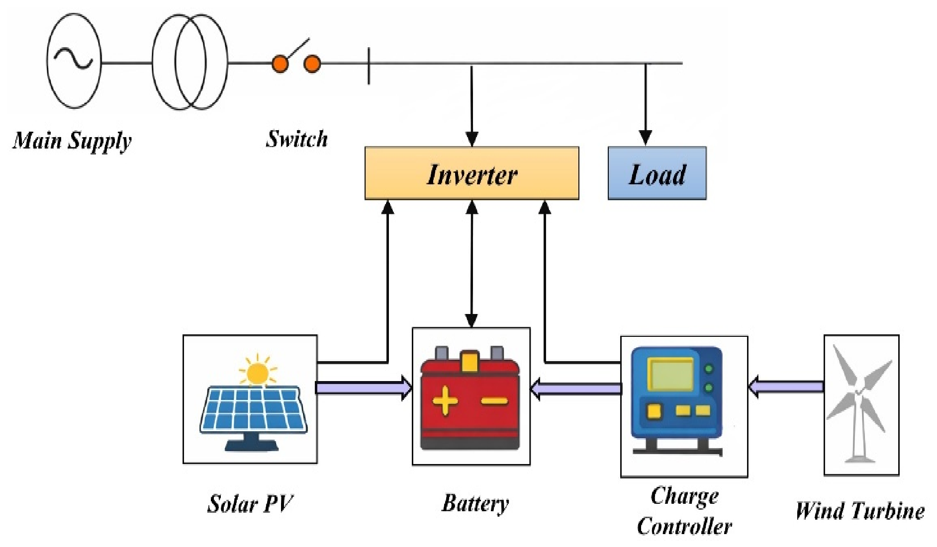
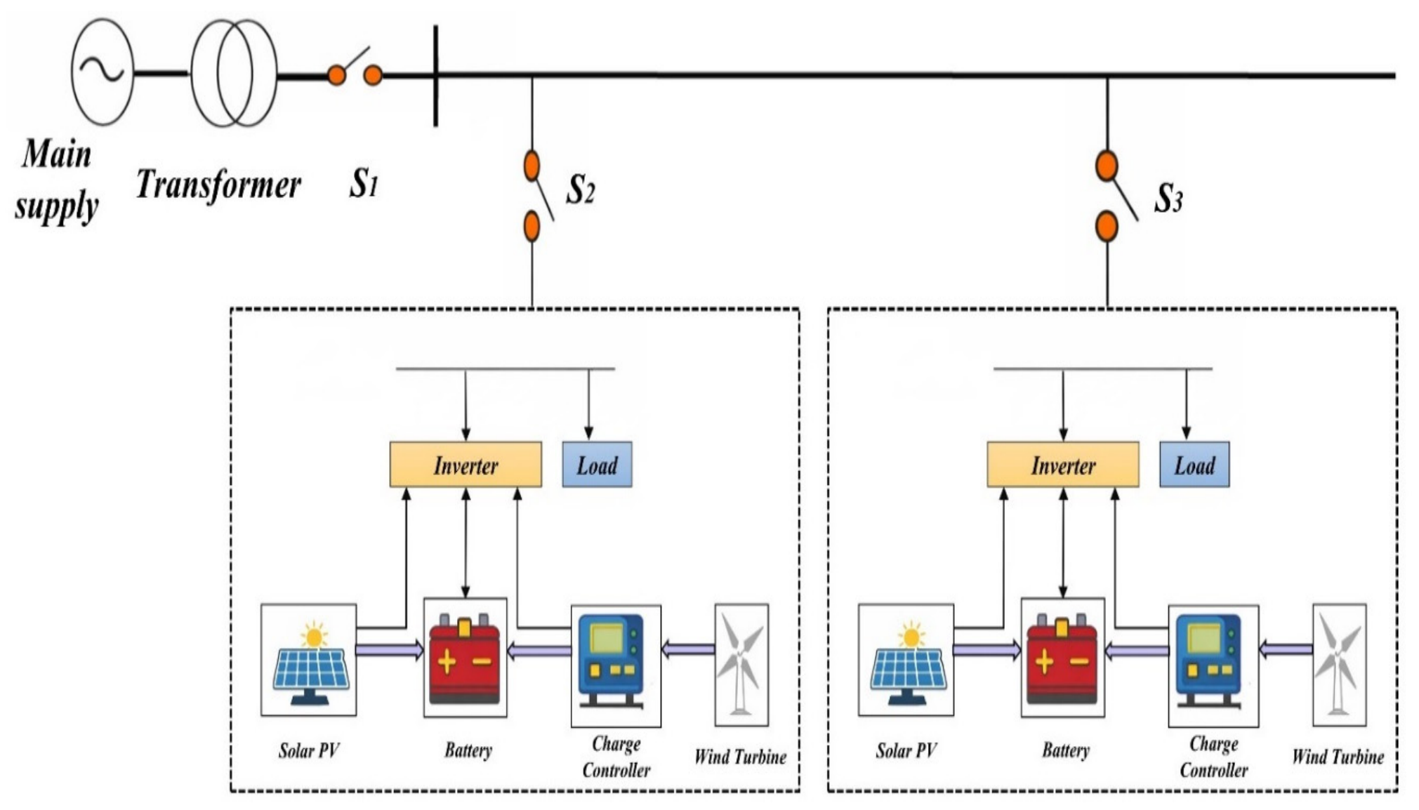
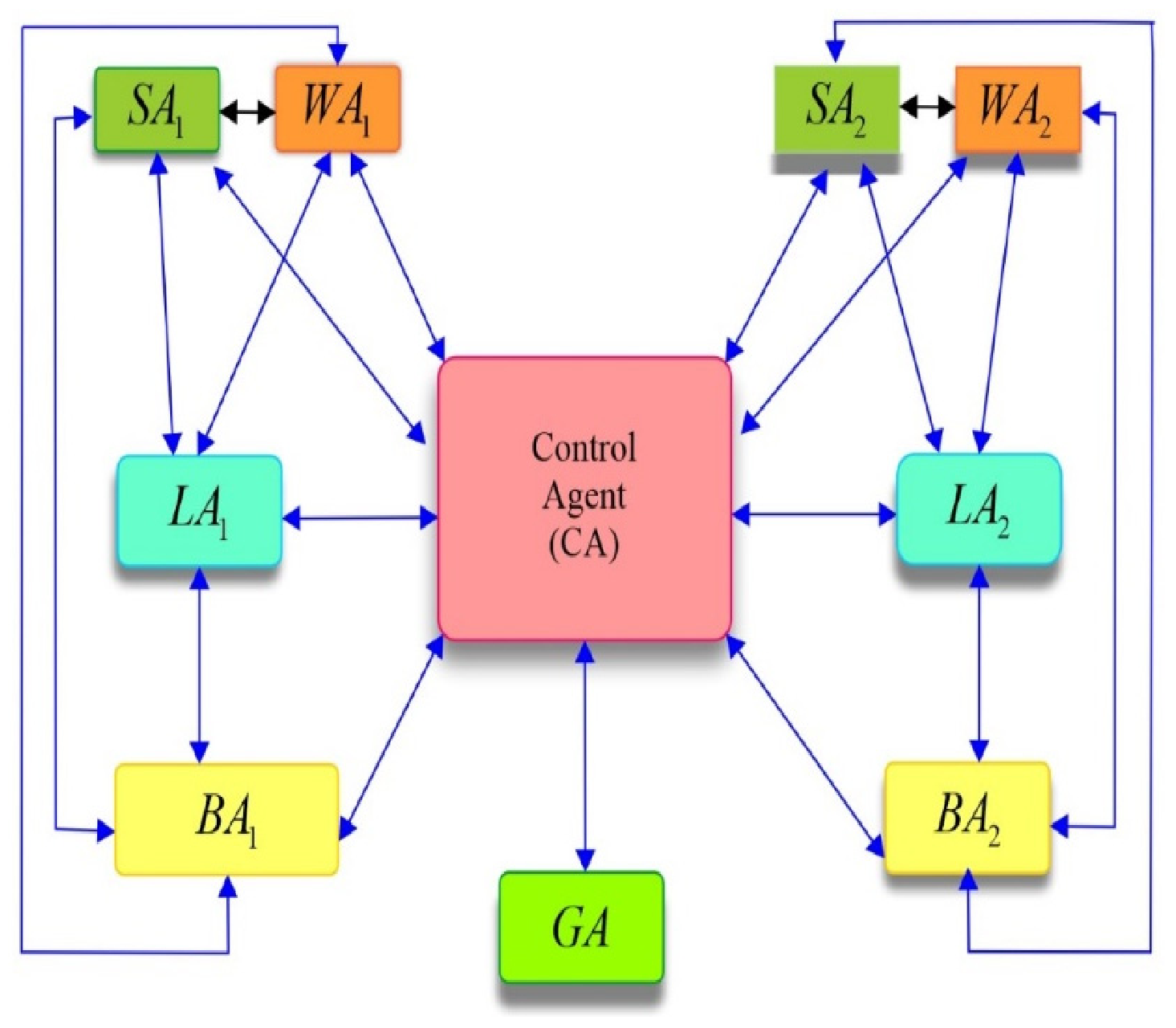
A hybrid microgrid system can be used in both coordinated mode with the main utility grid (grid-connected mode) and in decoupled mode (off-grid or islanded mode). This dual functionality can increase energy resiliency, solar and wind energy sources can be more fully penetrated, and power quality and system stability are also improved [20,21,22,23,24,25,26]. Through smart generation, storage and loads, the microgrids can be used to effectively reduce the challenges encountered by grid instability, increase in energy prices, and the need to have sustainable energy and low-carbon energy sources. Due to these benefits, the hybrid microgrid systems make them especially applicable in remote and isolated locations, industrial and business facilities, military camps, and disaster-prone areas, where consistent, uninterrupted and autonomous electricity is essential. Figure 1 illustrates the architecture of a single hybrid microgrid, and Figure 2 presents the dual microgrid configuration implemented in this work. In the dual-MG topology, each microgrid operates as an independent unit capable of islanded operation while also being interconnected via switch S1 to enable bidirectional inter-MG power exchange, coordinated by the Control Agent (CA) as described in Section 6.
Here, various components of a microgrid system and their arrangement are depicted.

3. Modelling of Microgrid Components

Modelling of a microgrid which comprises components like solar panels, a wind turbine, energy storage devices, power converters, loads, and control systems is essential for the design, analysis, and optimization of microgrid system performance through scheduling and allocation in power-aware applications. The prediction of the system’s behaviour across various operating situations optimizes energy distribution and guarantees grid stability and dependability will be as near the real-time situations when modelling is accurate [27,28,29,30,31]. The models presented in Table 2 are intentionally scoped to capture the essential input-output behaviours of each component at the energy management layer—i.e., the power generation, storage dynamics, and load characteristics relevant to the dispatch decisions made by the MAS agents. These models are consistent with those used in comparable published works on agent-based microgrid EMS and are appropriate for the hourly resolution EMS timescale at which the JADE agents operate. The mathematical modelling of microgrid components is presented in Table 2.

4. Multi-Agent System Using JADE

MAS involves several interacting intelligent agents collaborating each of which is capable of making autonomous decisions informed by its surroundings and internal conditions, being adept at managing the complexity and dynamic nature of microgrids [32,33,34,35,36,37,38]. MAS improve the performance of the microgrid system. The MAS algorithm is used for effective energy management. Every agent inside the system possesses the attributes given in Table 3.
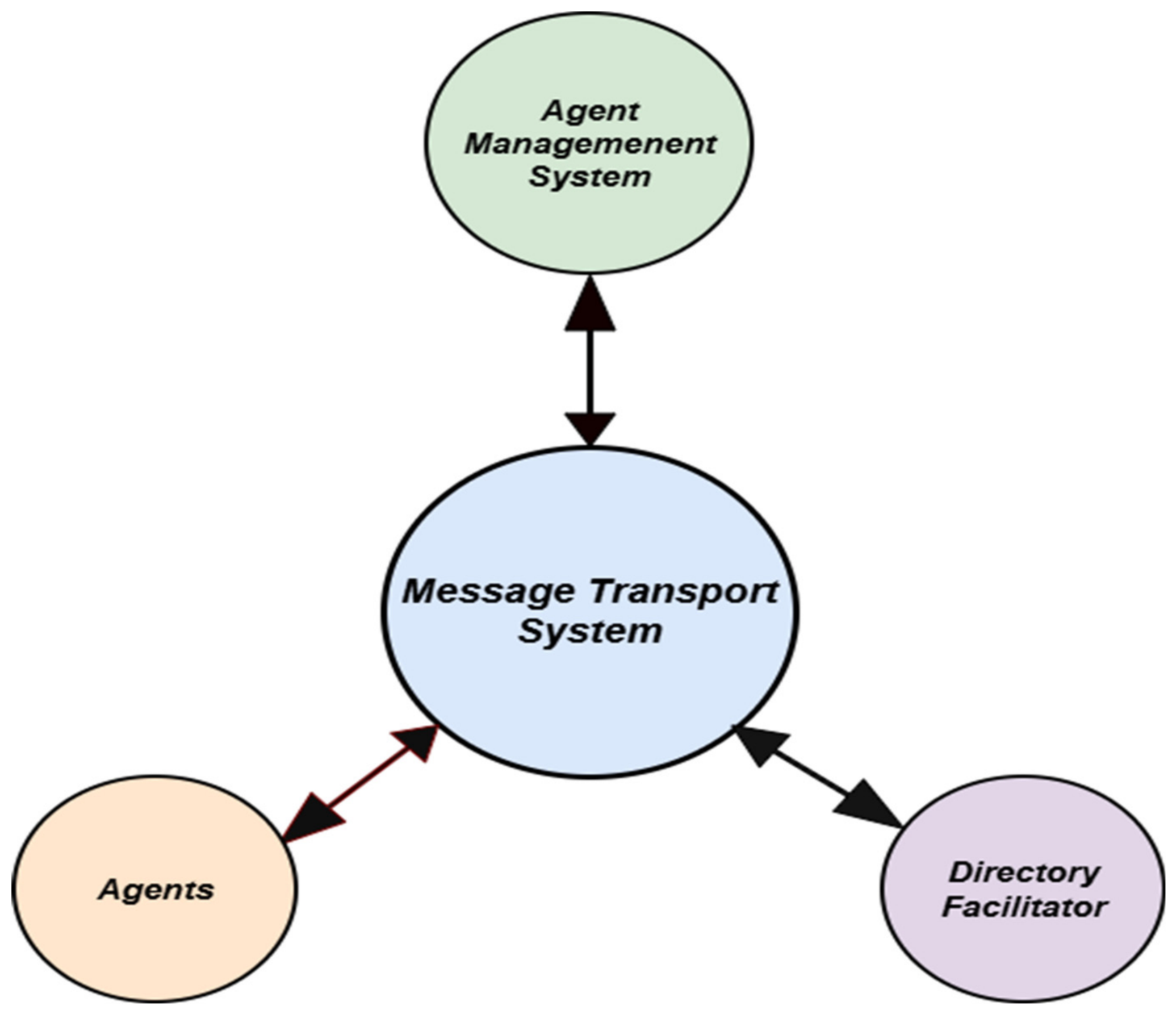
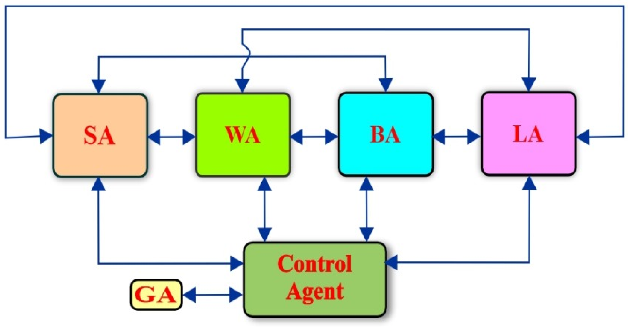
JADE is a popular, widely accepted open-source framework for constructing Multi-Agent Systems, developed in Java offering a framework for the creation and management of intelligent agents that utilize the FIPA communication (Foundation for Intelligent Physical Agents) standard. Principal attributes of JADE are FIPA-compliant agent communication, distributed architecture with platform independence, agent mobility, dynamic creation, directory and yellow pages services for agent identification, and integrated debugging and monitoring tools. The MAS model is shown in Figure 3.

4.1. Agent Decision-Making and Internal Logic

Each agent in the proposed MAS executes a local decision procedure based on its monitored state variables. The decision logic for each agent type is as follows in Table 4:

4.2. Agent Communication Protocol

All inter-agent communication is implemented using JADE’s FIPA-compliant ACL. The specific ACL performatives and their roles in the energy management cycle are explained in Table 5:
The complete message exchange sequence is captured in the Sniffer diagrams in Section 8.
Agent Communication Language (ACL) is used for communication between agents for collaborative actions. All the agents are put into the container and communication happens through ACL. The decentralization and distribution of the decision-making processes among individual autonomous agents, the individual objectives of agents and further the evolution of the global objectives are carried out with the help of communication among all these components.

5. Objective Function and System Constraints

5.1. Objective Function

The main objective is to maintain power balance in both single and dual microgrid configurations to provide operational stability and a reliable energy supply. This is attained by balancing the renewable generation, grid exchange and storage within the system load.
For a single microgrid, the power balance objective will be represented as follows:
m i n P p v t + P w i n d t + P b a t t e r y t + P e x c h a n g e t P T o t a l l o a d d e m a n d t
For a dual microgrid system, this is extended as follows:
m i n i = 1 2 P p v , i t + P w p , i t + P b , i t + P g , i t + P e x c h a n g e i n   i n t e r c o n n e c t e d   g r i d t P L , i t

5.2. System Constraints

5.2.1. Power Balance Constraint

At any time instant, the sum of generation should be equal to the sum of demand
P p v t + P w p t + P g t + P b d i s t = P L t + P b c h t
For dual microgrids at interconnection:
P e x , 1 t + P e x , 2 t = 0
The above equation shows the lossless power exchange between microgrids. This constraint is enforced by the Control Agent at every hourly decision cycle, ensuring that inter-MG power transfer is always balanced and that no uncompensated power flow occurs across the interconnection.

5.2.2. Storage Capacity Constraint

The SOC should balance the charging and discharging limits. This will be shown by
S O C m i n S O C t S O C m a x
The SOC dynamics are computed by
S O C t + 1 = S O C t + η c h P b c h t 1 η d i s P b d i s t E b r a t e d Δ t
where
η c h and η d i s are charging and discharging efficiencies;
E b r a t e d is the rated battery energy capacity;
Δ t is the step time control.
In this work, S O C m i n = 20% and S O C m a x = 90% chosen to prevent battery over-discharge and overcharge, thereby extending battery cycle life. These bounds are respected in all reported scenarios, as confirmed by the SOC profiles in Section 8.

5.2.3. Battery Power Limits

The battery charging and discharging is limited as follows for extended battery life.
0 P b c h t P b c h , m a x 0 P b d i s t P b d i s , m a x

6. Multi-Agent Systems-Based Autonomous Energy Management of Microgrid

The agent autonomously executes the most feasible operations based on hourly monitored parameters of wind power, solar power, load, and battery state of charge (SOC) for dynamic energy management of the hybrid microgrid in a distributed environment.
The agents shown in Table 6 simulate a MAS within a JADE environment for a single hybrid microgrid and two hybrid microgrid systems.

6.1. Single Hybrid Microgrid (Grid-Connected/Off-Grid)

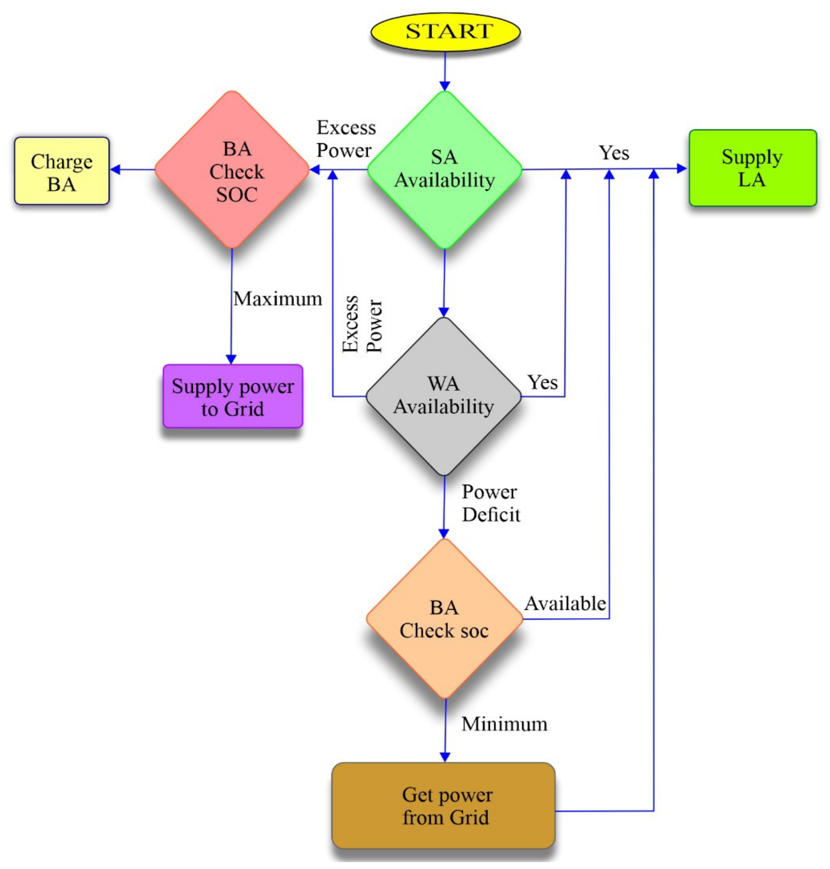
Figure 4 shows the flow chart including all potential applications of a single hybrid microgrid and Figure 5 shows the interaction of the agents. The control priority hierarchy—solar availability first, wind second, battery third, and grid last—is embedded in the CA’s decision procedure and ensures maximum renewable utilization before resorting to grid dependency. This priority ordering constitutes the conflict resolution protocol of the MAS: when multiple agents simultaneously propose power, the CA follows this deterministic hierarchy to arbitrate and allocate without ambiguity.
The implemented process is as follows:
For off-grid operation of a single hybrid microgrid, adhere to stages 1–4; for on-grid operation, proceed with steps 5–7.
Step 1: The Load Agent (LA) contacts the Control Agent (CA) with power requirements.
Step 2: The CA verifies the availability of the Solar Agent (SA) and solicits electricity from the SA, which autonomously supplies power to the LA. Surplus electricity is allocated to the Battery Agent (BA).
Step 3: The CA verifies the availability of the wind Agent (WA) and solicits electricity from the WA, subsequently receiving the available power from the WA. Surplus electricity is allocated to BA.
Step 4: If power remains necessary, the CA assesses the SOC of the BA. If the SOC exceeds the minimum state of charge ( S O C m i n ), it draws power from the battery array (BA).
Step 5: If the SOC of the BA meets the minimal threshold, then the CA verifies the availability of grid power.
Step 6: If necessary, draw electricity from GA whenever the battery’s SOC hits its minimum and supply it to LA.
Step 7: Excess power is transmitted to the GA when the battery’s SOC reaches its maximum capacity.

6.2. Two Hybrid Microgrid Systems

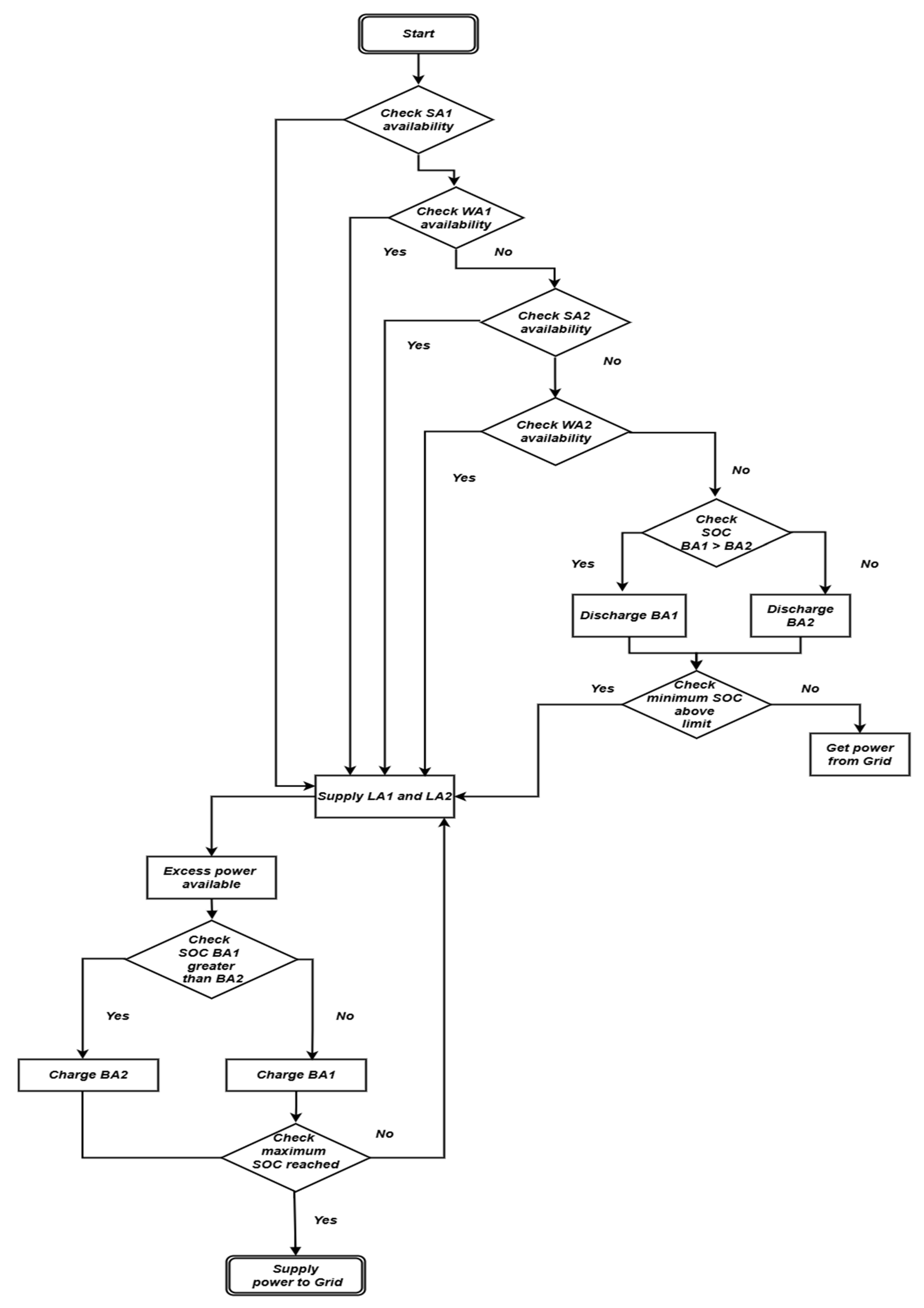
Figure 6 illustrates the flow chart including all potential applications of a two-hybrid microgrid system and Figure 7 shows the interaction of the agents. In the dual-MG configuration, the inter-MG power exchange is governed by the following explicit rules enforced by the Control Agent: (i) when surplus generation exists in either MG, the CA charges the battery with the lower SOC (cross-MG SOC balancing); (ii) when a power deficit exists and local batteries cannot fully satisfy demand, the CA discharges the battery with the higher SOC, regardless of which MG it belongs to; (iii) inter-MG exchange is subject to the lossless balance constraint P_(ex,1) (t) + P_(ex,2) (t) = 0 (Section 5.2.1); and (iv) grid interaction is invoked only when both BA1 and BA2 have reached their respective SOC limits. These rules ensure fair, efficient, and constraint-compliant power sharing between the two microgrids at every decision step.
The agents listed below simulate a MAS within a JADE environment for two hybrid microgrids, both in grid-connected and off-grid configurations.
For off-grid operation of hybrid microgrids, adhere to stages 1–6; for on-grid operation, proceed with steps 7–9.
Step 1: Load Agent 1 (LA1) and Load Agent 2 (LA2) solicit power requirements from the Control Agent (CA).
Step 2: The CA verifies the availability of SA1 and grants authority to LA1.Should extra power be available, assess the SOC of BA1 and BA2, and charge the battery with the lower SOC.
Step 3: CA verifies WA1 availability and allocates power to LA1.In the presence of extra power, assess the SOC of BA1 and BA2, and charge the battery with the lower SOC.
Step 4: The CA verifies the availability of SA2 and grants authority to LA2.In the presence of extra power, assess the SOC of BA1 and BA2, and charge the battery with the lower SOC.
Step 5: The CA verifies the availability of WA2 and grants authority to LA2.In the presence of extra power, assess the SOC of BA1 and BA2, and charge the battery with the lower SOC.
Step 6: If power remains necessary, CA assesses the SOC of BA1 and BA2, procures power from the battery with the higher SOC, and distributes it to LA1 and LA2.
Step 7: If the SOC of BA1 and BA2 attains the minimal threshold, then the Control Agent (CA) assesses the grid availability of power.
Step 8: If power remains necessary, it is sourced from the Grid Agent (GA) and distributed to LA1 and LA2.
Step 9: The surplus electricity is allocated to the Grid Agent (GA) once BA1 and BA2 are completely charged.

7. Realtime Implementation of Hybrid Microgrid

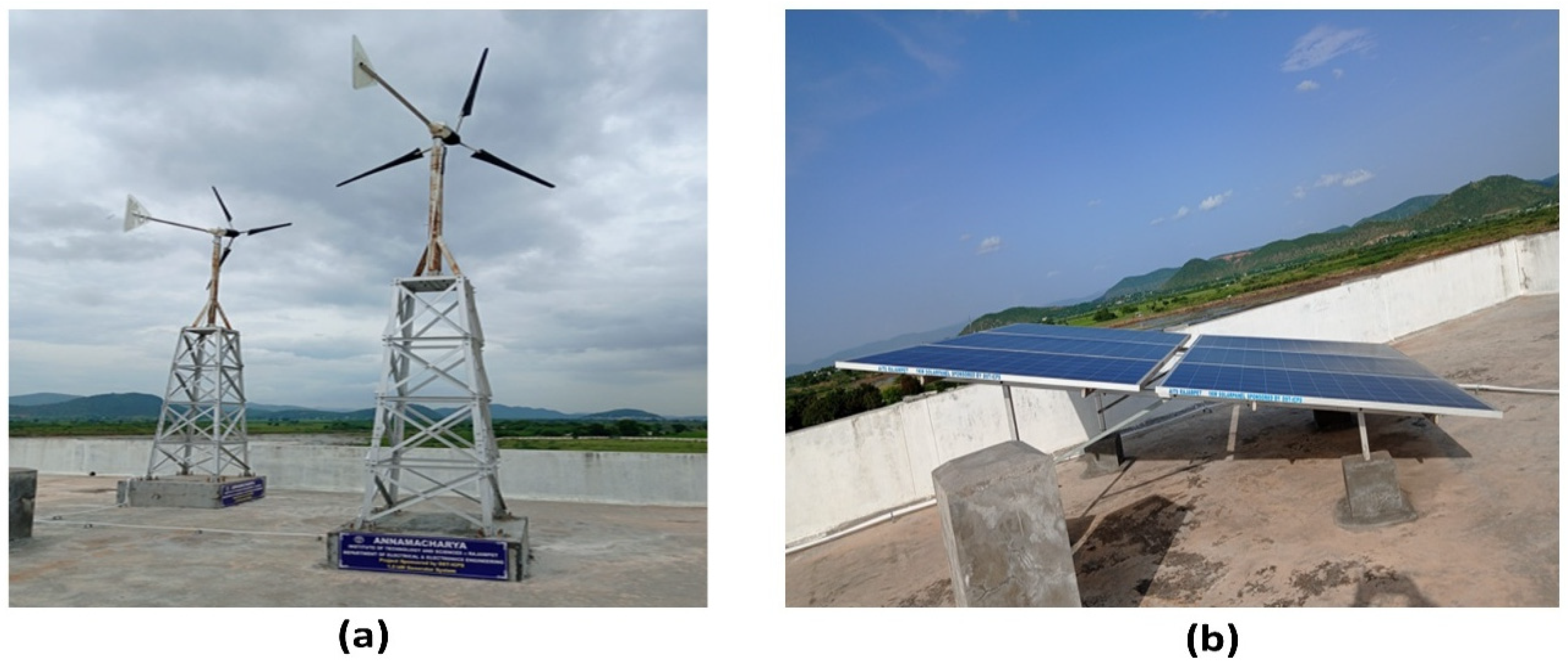
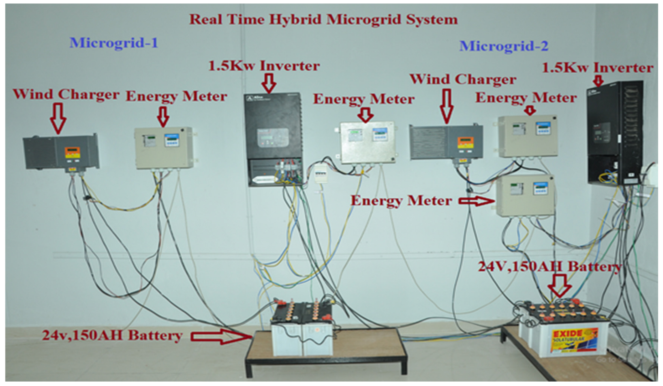
In this paper, the term ‘real-time’ refers to real-time energy management (EMS)—a well-established designation in the microgrid literature [4,5,6,7,8,9] denoting dispatch-level control operating at the minute-to-hour timescale, as opposed to inner voltage/current control loops operating at the millisecond timescale. The JADE agents execute hourly decision cycles driven by actual sensor measurements, which is the standard operating frequency for campus-scale EMS deployments. The physical hardware (solar PV, wind turbines, batteries, metres) provides measured inputs; the JADE software version 4.6.0 processes these inputs and issues control decisions; and the Sniffer diagrams confirm actual live agent execution. Two 1 kW solar PV systems and two 1.5 kW wind-generating systems are erected on the rooftop of the electrical department, with control systems, measuring equipment, and sensors connected to the research laboratory of the department. These are configured as a microgrid system having a 1 kW solar PV system, a 1.5 kW wind turbine system, a 24 V, 150 AH storage system, and a local load.Microgrid-1 supplies power to the connected loads in various rooms such as rooms 303, 304, and 305 of the electrical department, while microgrid-2 provides power to the connected loads in rooms 403 and 404. Figure 8 illustrates the installed configurations. The microgrid control mechanism is illustrated in Figure 9. The connected loads of microgrid-1 and microgrid-2 are presented in Table 7 and Table 8, respectively. Table 9 shows the comparative load profile with priority index for the dual microgrid system. The sensors consistently monitor all electrical loads while assessing wind and solar energy on an hourly basis.
Sensor specifications: The energy metres used in the installation are commercial-grade metres conforming to IEC 62053 Class 1 standards [39], with a typical power measurement accuracy of ±1–2%. Current sensors used for battery SOC estimation via coulomb counting have a measurement accuracy of ±0.5% FS. While sensor measurement noise introduces a small cumulative error in the SOC dynamic model, the SOC profiles reported in Table 10, Table 11, Table 12 and Table 13 are consistent with the observed charge/discharge behaviour across the 24 h operational periods. The natural day-to-day variability in the recorded wind (60 W–520 W) and solar (0 W–910 W) profiles demonstrates the system’s adaptive response to stochastic renewable generation, providing an implicit sensitivity validation across the observed input range.

Load Characteristics of Microgrids

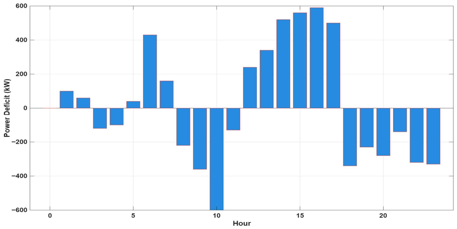
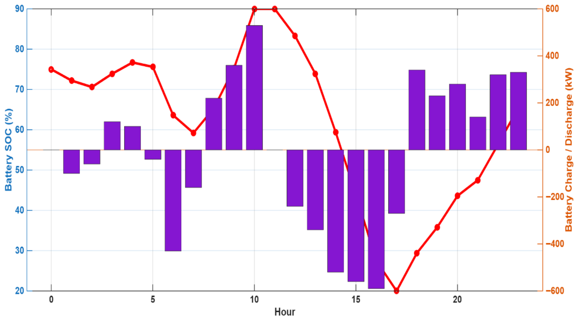
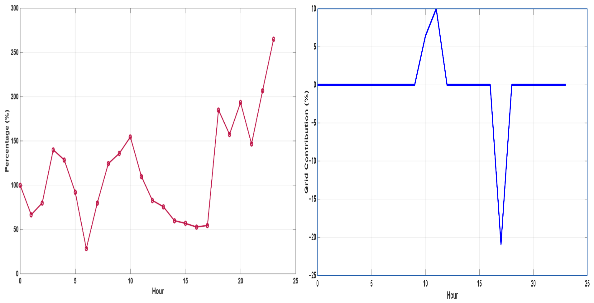
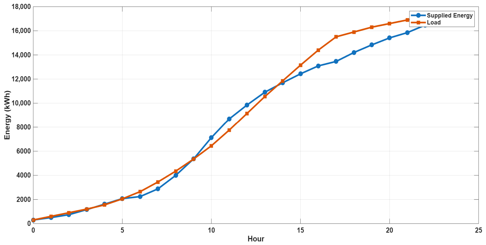
The variation in load in the classrooms supplied by microgrids 1 and 2 is analyzed for 24 h along with the power generated from solar and wind units. At any point of time the load requirement of the classrooms is managed by the solar, wind and power available in the battery. Any further deficiency is managed by taking power from the other microgrid through distributed energy management. Power deficit analysis is shown in Figure 10. The battery SOC and charge–discharge profile are shown in Figure 11. Renewable utilization to meet load and grid dependency over 24 hrs shown in Figure 12. Cumulative energy vs. load is shown in Figure 13.

8. Real-Time Simulation Results and Discussion

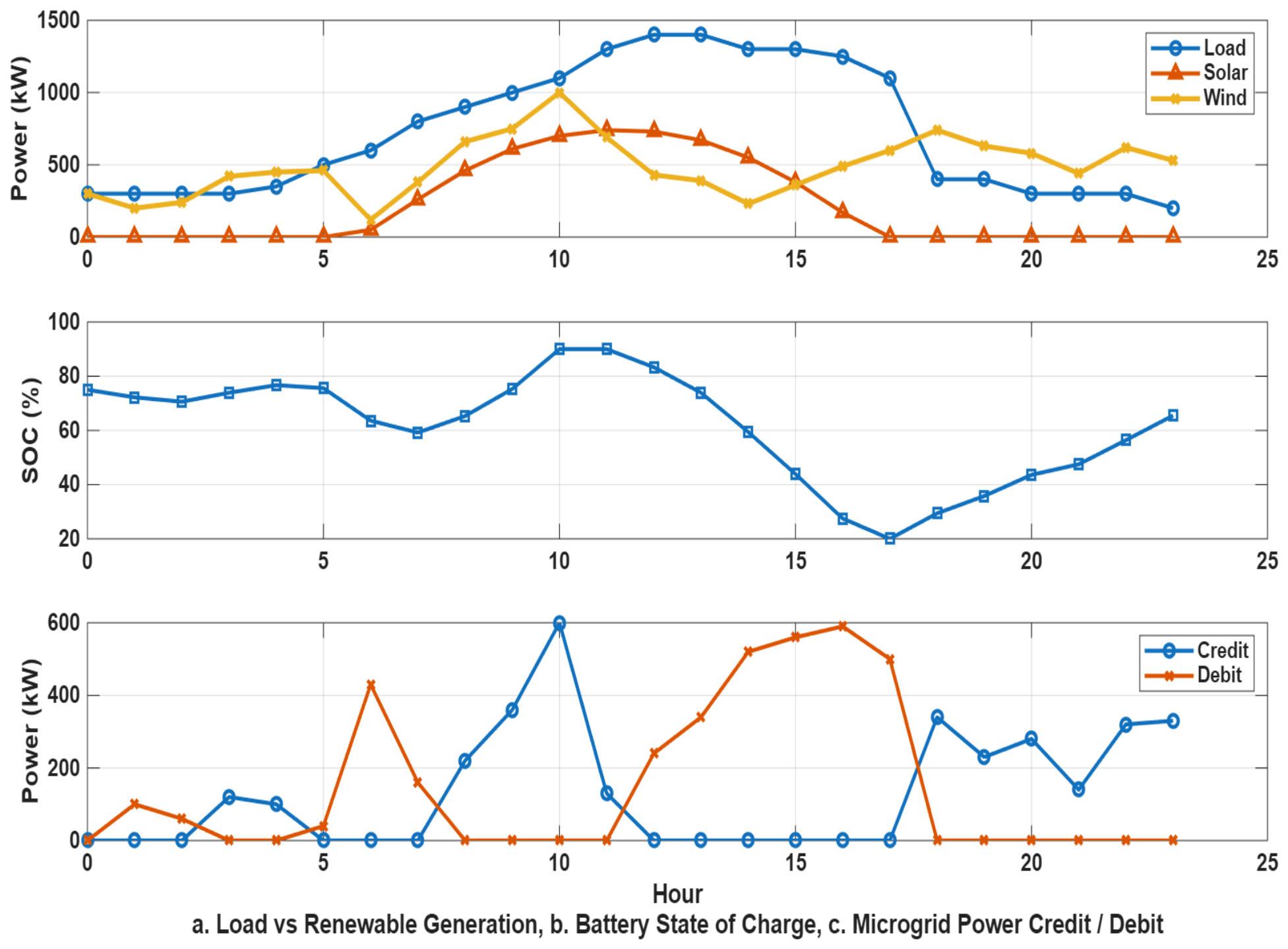
This section presents the results of the JADE-based MAS across all four operating scenarios, based on 24 h of real operational data collected from the campus microgrid installation. Results are discussed in Section 8.1, Section 8.2, Section 8.3 and Section 8.4. Figure captions have been updated to include physical units for all axes; all power quantities are in Watts (W), SOC in percentage (%), and time in hours (h).

8.1. Single Off-Grid Hybrid Microgrid System

The power generated by solar and wind is monitored and the corresponding load variation in the specified classrooms where microgrid-1 is supplying power is recorded for 24 h duration. Table 10 presents the optimized values for the operation of a single hybrid microgrid in islanded (off-grid) mode. The nature of available power and surplus, scarcity in every hour is considered and the Control Agent takes the appropriate action for stable operation of the microgrid.
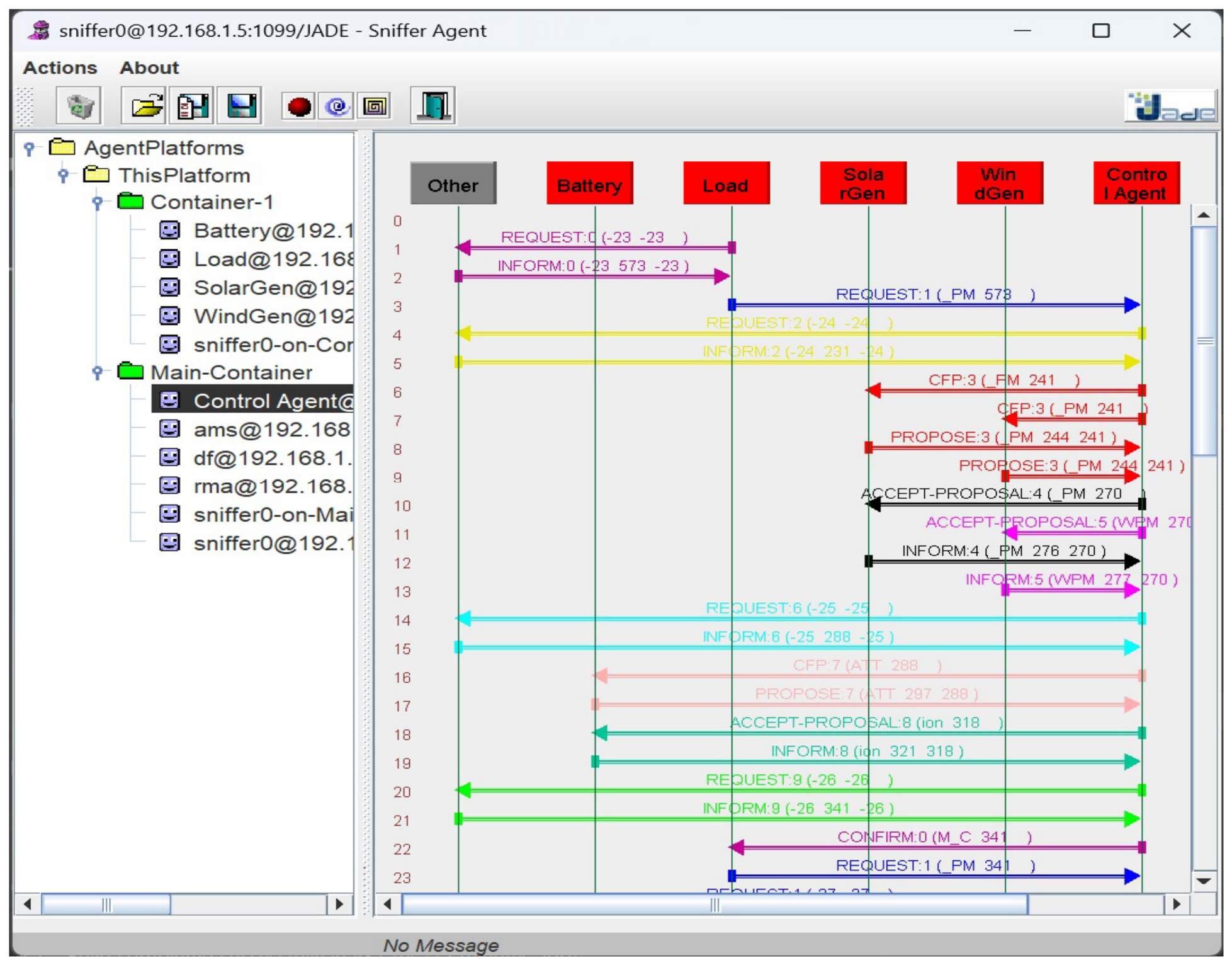
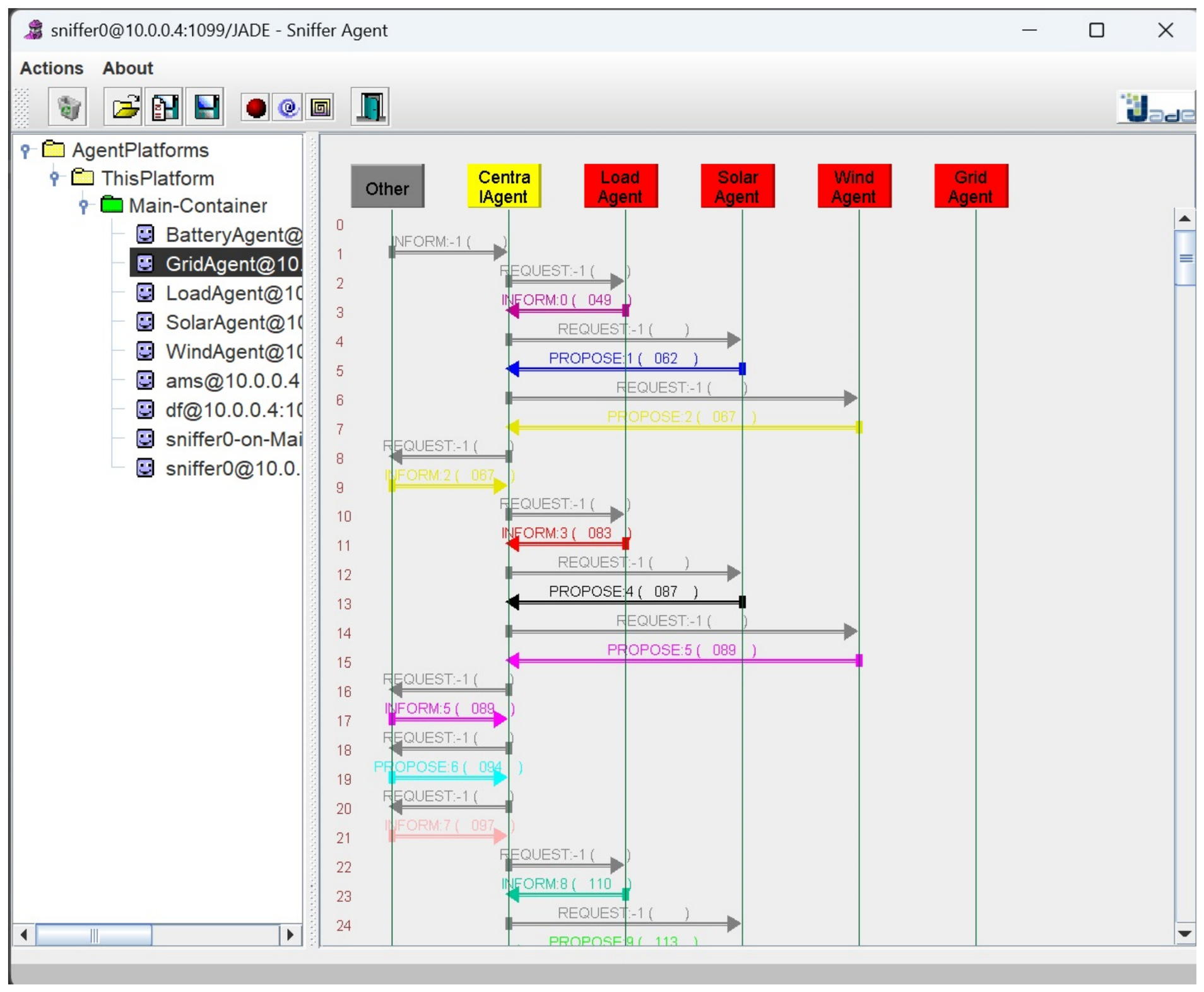
As can be observed, between the 0th and 6th hour, the load exceeds power generation, causing the battery to discharge and the SOC to drop from 75% to 70.7322% as shown in Figure 14. Between the 7th and 16th hours, solar power increases, reaching a high of 910 W at the 15th hour. This surplus enables the battery to switch to charging mode, with the SOC recovering to 80.3275% by the 15th hour. During the 17th to the 23rd hour, i.e., evening, a change in wind power is noted, causing the battery to alternate between charging and discharging. This agent operation is implemented in the MAS execution platform JADE and the agent communication diagram called the Sniffer diagram is shown in Figure 15. This diagram shows all the agents registered in the Agent Management System and the load agent requests the Control Agent for power. The Control Agent can see the nature of agents through the Directory Facilitator Agent and communicate with agents according to the requirement at that point in time. The intercommunication between agents at every instant and based on the strategic decision by the Control Agent and the outcome action is reflected in the form of communication.

8.2. Single On-Grid Hybrid Microgrid System

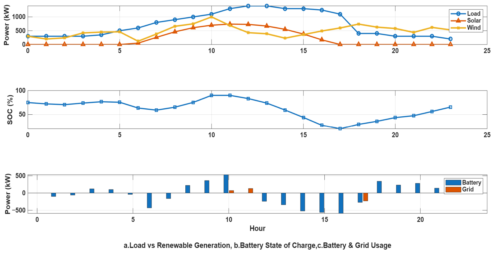
Table 11 presents the optimized values for the operation of a single hybrid microgrid in grid-connected (on-grid) mode during 24 h duration.
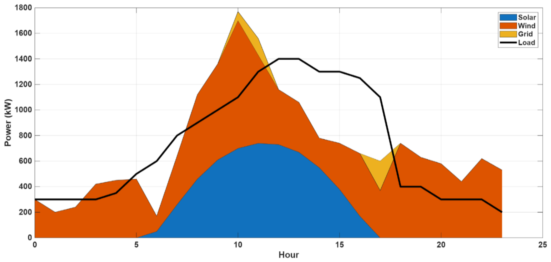
Table 11 demonstrates clearly that the overall power generation and battery storage will adequately meet the demand during the 0th to 9th, 12th to 16th, and 18th to 23rd hours. As the generation is surplus and the battery is fully charged, the microgrid delivers surplus power to the grid during the 10th and 11th hours. At the 17th hour, with minimal wind and solar power output and exhausted battery reserves, the microgrid draws power from the grid as shown in Figure 16. The energy flow diagram is shown in Figure 17 and the Sniffer diagram is shown in Figure 18. Here, even after receiving power from the available solar wind and the battery, if the load requires further power, it can be supplied from the Grid Agent.

8.3. Two Off-Grid Hybrid Microgrid Systems

Table 12 presents the optimized values for the operation of a two-hybrid microgrid system in islanded (off-grid) mode during a 24 h duration.
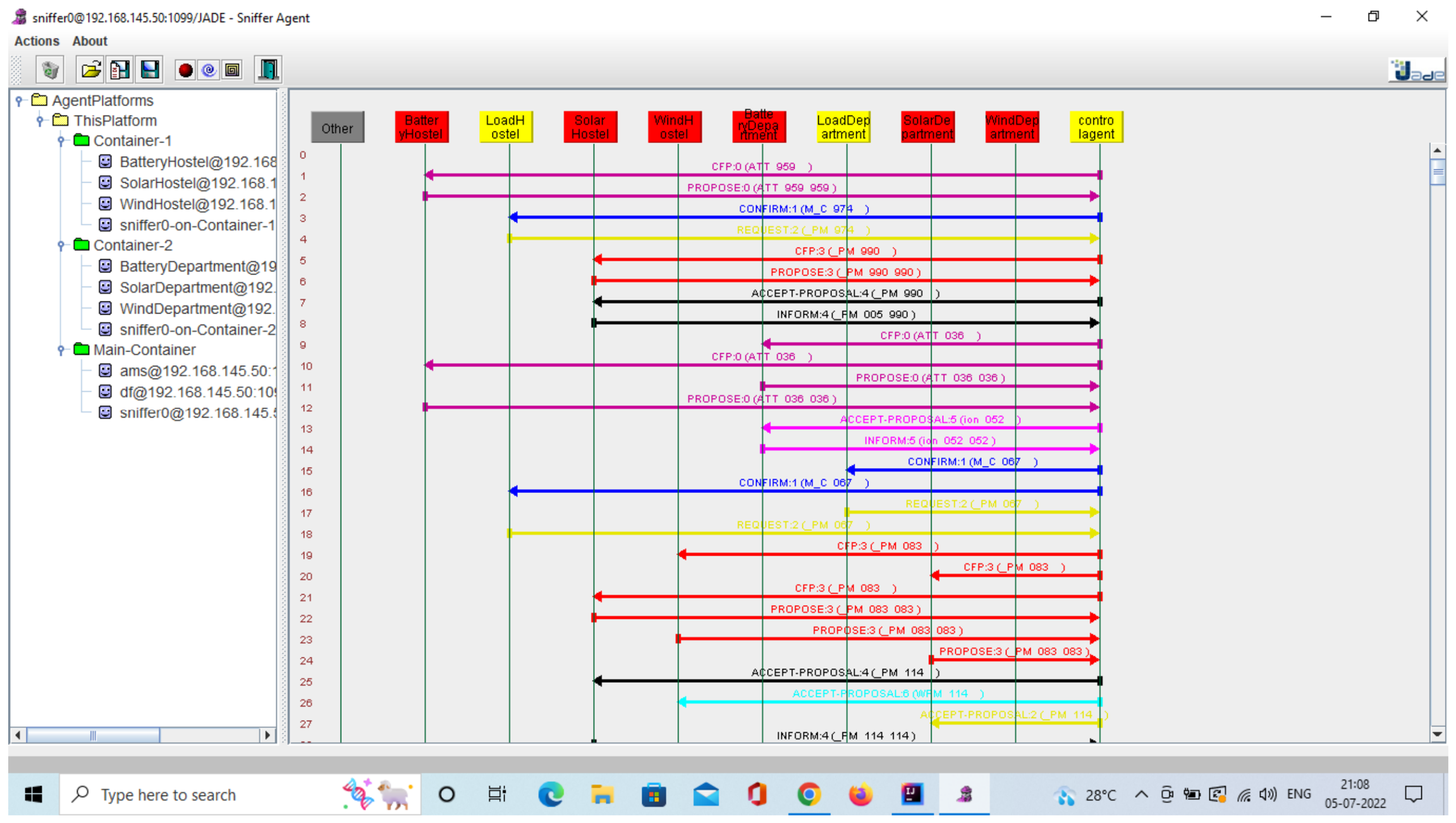
It is clearly evident from Table 12 that between the 0th and6th hour, power generation is inadequate to satisfy the load in both microgrids; thus, power from the battery with a greater SOC will be discharged. Between the 7th and17th hours, as solar power generation increases, the overall power output exceeds the load demand causing the excess power to charge the battery. Between the 18th and23rd hours, when the output of solar power reduces, battery power must be utilized to satisfy load demands; hence, the battery with a greater state of charge will be discharged. The sniffer diagram is shown in Figure 19. Here, both the microgrids collectively manage the deficiency of power. The load at microgrid-1 can access the power from the solar in microgrid 2 or vice versa.

8.4. Two On-Grid Hybrid Microgrid Systems

Table 13 presents the optimized values for the operation of a two-hybrid microgrid system in grid-connected (on-grid) mode during a 24 h duration.
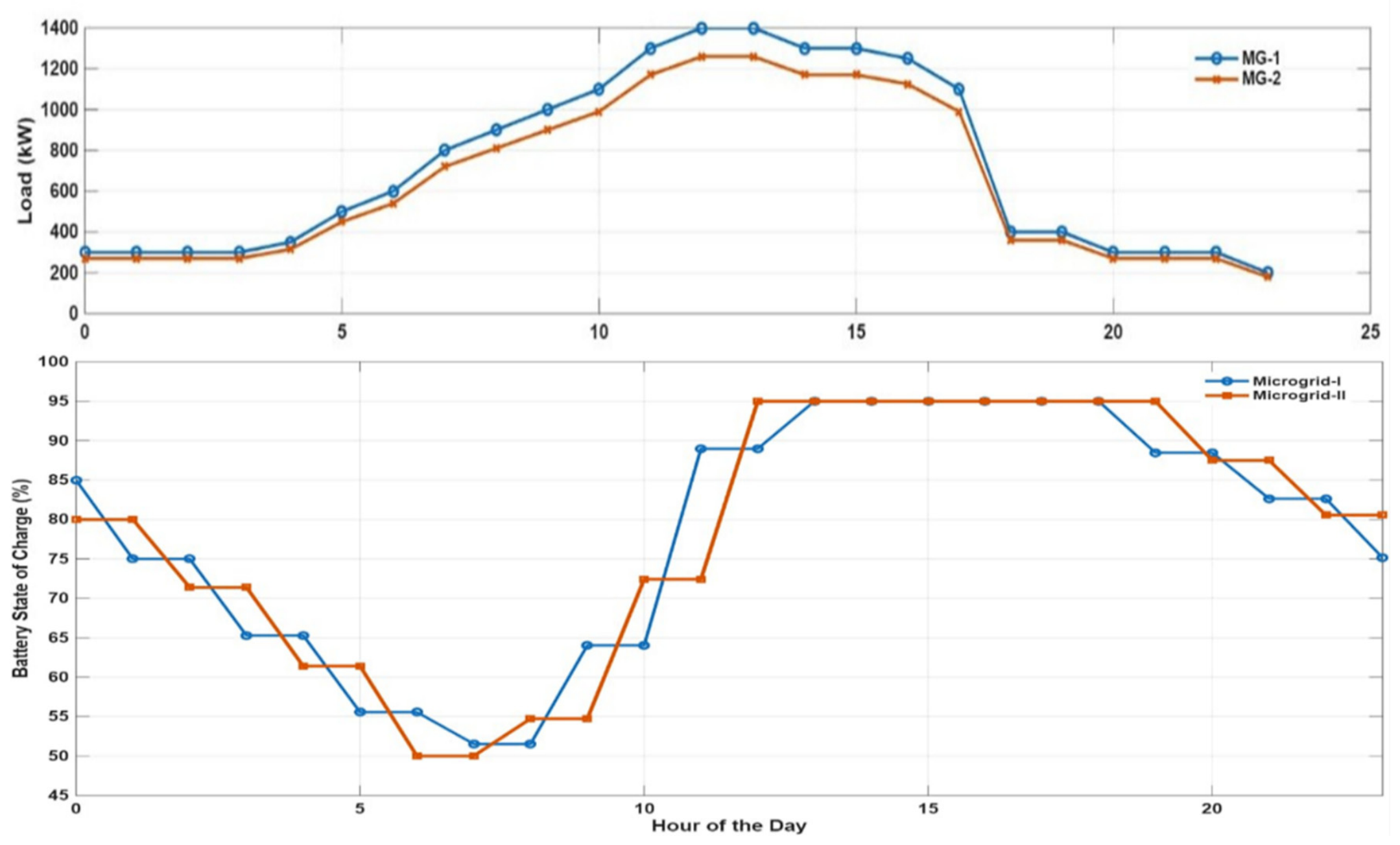
From Table 13 it is evident that between the 0th and10th hours and between the 18th and 23rd hours, energy balance is attained in the microgrids, with the batteries operating in charging and discharging modes. From the 11th to the 17th hour, the excess power in the microgrids is sent to the grid as shown in Figure 20. Thus, the agent takes autonomous action and if it is not able to take autonomous action, it gets help from the control agent to take action towards global objectives and thereby evolves to participate in larger goals.

9. Comparative Analysis

This section compares the proposed JADE-based MAS against a conventional JavaScript-based centralized EMS. Table 14 below provides a structured quantitative comparison across eight evaluation dimensions. Both systems are evaluated on identical 24 h input data—the same hourly load, solar, and wind profiles—ensuring a fair, unbiased comparison. Table 15 presents the JavaScript EMS results.
As Table 14, Table 15, Table 16, Table 17 and Table 18 demonstrates, while both approaches yield numerically equivalent energy dispatch results for the same input data—thereby validating the correctness of the MAS agent decisions against a known baseline—the JADE-based MAS offers substantial qualitative and architectural advantages. These advantages become decisive in larger, more complex multi-MG deployments where centralized EMS architectures fail due to scalability limitations, single-point-of-failure vulnerabilities, and inability to support autonomous inter-MG coordination. The equivalence in energy outcomes is itself a meaningful result: it confirms that decentralized multi-agent decision-making does not compromise dispatch optimality relative to centralized control, while delivering superior architectural properties.

10. Conclusions

This paper has presented a JADE-based Multi-Agent System (MAS) for real-time energy management of a low-voltage hybrid dual microgrid system, physically implemented on a campus rooftop and in a laboratory. The proposed system comprises two interconnected microgrids, each rated at 2.5 kW (1 kW solar PV + 1.5 kW wind), operating on a 24 V DC bus with 150 Ah battery storage and validated across four operating scenarios: single MG off-grid, single MG on-grid, dual MG off-grid, and dual MG on-grid.
The key findings of this work are as follows: (i) The JADE-based MAS successfully maintains power balance at every hourly decision step across all four scenarios, with zero unmet load demand; (ii) battery SOC is maintained within the safe operating bounds of 20–90% in all cases, confirming constraint-compliant autonomous operation; (iii) the inter-MG SOC-balancing mechanism effectively enables cross-MG power sharing, reducing grid dependency in the dual-MG configuration; and (iv) a direct comparison with a centralized JavaScript-based EMS confirms equivalent dispatch accuracy while demonstrating the superior scalability, fault tolerance, and modularity of the proposed decentralized MAS architecture.
The limitations of the current study that should be noted include: the experimental platform is a campus-scale, low-voltage system (2.5 kW per MG, 24 V DC bus), and extrapolation of conclusions to higher-voltage, larger-scale networks requires further validation; the EMS operates at an hourly scheduling timescale and does not address inner voltage/current control loops; formal fault injection testing (e.g., agent failure, communication disruption, generation dropout) has not been conducted, though the JADE platform’s AMS and DF services provide inherent recovery mechanisms; and the battery SOC model relies on coulomb counting, which accumulates measurement error over time.
Inherent features of MAS are leveraged for dynamic adaptation and distributed optimization to get the best of the service to the consumers across the network all the time, leading to economic and environmental optimization.
Future endeavours will concentrate on incorporating sophisticated machine learning methodologies and evaluating the framework within extensive, linked microgrid networks.

Author Contributions

Conceptualization, P.K.R.K. and P.B.; methodology, P.K.R.K.; software, P.K.R.K.; validation, P.K.R.K. and P.B.; formal analysis, P.K.R.K.; investigation, P.K.R.K.; resources, P.K.R.K.; data curation, P.K.R.K.; writing—original draft preparation, P.K.R.K.; writing—review and editing, P.B.; visualization, P.K.R.K.; supervision, P.B.; project administration, P.K.R.K.; funding acquisition, P.K.R.K. All authors have read and agreed to the published version of the manuscript.

Funding

This research was funded by “DST-Interdisciplinary Cyber Physical System, New Delhi, India, Grant Number: DST/ICPS/CPS-Individual/2018/607” and “APC received no external funding”.

Institutional Review Board Statement

Not applicable.

Informed Consent Statement

Not applicable.

Data Availability Statement

The original contributions presented in this study are included in the article. Further inquiries can be directed to the corresponding author.

Acknowledgments

The authors expresses gratitude to Jawaharlal Nehru Technological University (JNTU) Anantapur, and Annamacharya Institute of Technology and Sciences (AITS) for their indispensable support in facilitating the advancement of innovative research outcomes.

Conflicts of Interest

The authors declare no conflicts of interest.

Abbreviations

The following abbreviations are used in this manuscript:
BESBattery Energy Storage
MGMicrogrid
JADEJava Agent DEvelopment framework
RESRenewable energy sources
ESSEnergy storage systems
LFALevy Flight Algorithm
PSOParticle Swarm optimization
GAGenetic Algorithms
MPCModel predictive control
MASMulti-Agent Systems
FIPAFoundation for Intelligent Physical Agents
ACLAgent Communication Language
SOCstate of charge
LALoad Agent
CAControl Agent
GAGrid Agent
SASolar Agent
WAWind Agent
BABattery Agent

References

  1. Bharatee, A.; Ray, P.K.; Ghosh, A. A Power Management Scheme for Grid-connected PV Integrated with Hybrid Energy Storage System. J. Mod. Power Syst. Clean Energy 2022, 10, 954–963. [Google Scholar] [CrossRef]
  2. Thirugnanam, K.; El Moursi, M.S.; Khadkikar, V.; Zeineldin, H.H.; Al Hosani, M. Energy Management Strategy of a Reconfigurable Grid-Tied Hybrid AC/DC Microgrid for Commercial Building Applications. IEEE Trans. Smart Grid 2022, 13, 1720–1738. [Google Scholar] [CrossRef]
  3. Patel, S.; Ghosh, A.; Ray, P.K.; Gurugubelli, V. Effective Power Management Strategy and Control of a Hybrid Microgrid with Hybrid Energy Storage Systems. IEEE Trans. Ind. Appl. 2023, 59, 7341–7355. [Google Scholar] [CrossRef]
  4. Modu, B.; Abdullah, M.P.; Alkassem, A.; Hamza, M.F. Optimal rule-based energy management and sizing of a grid-connected renewable energy microgrid with hybrid storage using Levy Flight Algorithm. Energy Nexus 2024, 16, 100333. [Google Scholar] [CrossRef]
  5. Manojkumar, R.; Reddy, C.K.; Yuvaraj, T.; Bajaj, M.; Blazek, V. Optimized rule-based energy management for AC/DC hybrid microgrids using price-based demand response. In e-Prime-Advances in Electrical Engineering, Electronics and Energy; Elsevier: Amsterdam, The Netherlands, 2025; Volume 14, p. 101132. [Google Scholar]
  6. Pajares, A.; Vivas, F.J.; Blasco, X.; Herrero, J.M.; Segura, F.; Andújar, J.M. A novel energy management system based on move-blocking based predictive control for use in microgrid control. Energy Convers. Manag. 2025, 345, 120400. [Google Scholar] [CrossRef]
  7. Osama, A.; Allam, D.; Zobaa, A.F.; Eteiba, M.B. Energy Management Solution for Islanding Based on a Dynamic Neuro-Fuzzy-Optical Microscope Algorithm. IEEE Access 2025, 13, 162256–162272. [Google Scholar] [CrossRef]
  8. Luo, X.; Shang, K.; Li, X.; Guan, X. Hybrid Energy Management of Ship Microgrids Based on a Novel Adaptive Accelerated Gravitational Search Algorithm. IEEE Trans. Transp. Electrif. 2025, 11, 11816–11828. [Google Scholar] [CrossRef]
  9. Dai, S. Optimal energy management of multi-energy multi-microgrid networks using mountain gazelle optimizer for cost and emission reduction. Energy 2025, 329, 136640. [Google Scholar] [CrossRef]
  10. Yoldas, Y.; Onen, A.; Alawasa, K.; El Haffar, A.; Ahshan, R.; Islam, M.R.; Muyeen, S.M.; Noorfatima, N.; Jung, J. A Framework-Based Multi-Agent Coordination for Enhanced Microgrid Energy Management at the Secondary Control Layer. IEEE Trans. Appl. Supercond. 2024, 34, 5403005. [Google Scholar] [CrossRef]
  11. Bhattar, C.L.; Chaudhari, M.A. Decentralized Agent Based Real-Time Energy Management Framework for Hybrid Low-Voltage Multi microgrid System. IEEE Syst. J. 2025, 19, 1109–1120. [Google Scholar] [CrossRef]
  12. Tieng, H.; Ou, T.C.; Tsai, T.H.; Li, Y.Y.; Hung, M.H.; Cheng, F.T. I4. 2-GiM: A novel green intelligent manufacturing framework for net zero. IEEE Trans. Autom. Sci. Eng. 2023, 22, 18030–18050. [Google Scholar] [CrossRef]
  13. Anvari-Moghaddam, A.; Rahimi-Kian, A.; Mirian, M.S.; Guerrero, J.M. A multi-agent-based energy management solution for integrated buildings and microgrid system. Appl. Energy 2017, 203, 41–56. [Google Scholar] [CrossRef]
  14. Zohaib, A.; Akram, F.; Khalid, S.; Nawaz, H.; Rehman, M.U. Hybrid deep learning-based load forecasting and AI-driven energy management for grid-connected multi-microgrids. Comput. Electr. Eng. 2026, 131, 110915. [Google Scholar] [CrossRef]
  15. Mohan, A.; Thirumala, K.; Prakash, J.J.; Ilango, G.S. Energy management of grid-interconnected multi-microgrids based on adjustable power and greenhouse gas credits. Renew. Energy 2026, 256, 124180. [Google Scholar] [CrossRef]
  16. Singh, I.; Pavithra, S.; Rajesh, K. Resilient solar microgrid management using multi-agent reinforcement learning and quantum-based action selection. Results Eng. 2025, 28, 107633. [Google Scholar] [CrossRef]
  17. Raju, L.; Milton, R.S.; Mahadevan, S. Application of Multi Agent Systems in Automation of Distributed Energy Management in Micro-grid using MACSimJX. In Intelligent Automation & Soft Computing; Taylor & Francis: Abingdon, UK, 2017. [Google Scholar]
  18. Sami, B.S. Intelligent Energy Management for Off-Grid Renewable Hybrid System Using Multi-Agent Approach. IEEE Access 2020, 8, 8681–8696. [Google Scholar] [CrossRef]
  19. Manbachi, M.; Ordonez, M. Intelligent Agent-Based Energy Management System for Islanded AC–DC Microgrids. IEEE Trans. Ind. Inform. 2020, 16, 4603–4614. [Google Scholar] [CrossRef]
  20. Alluraiah, N.C.; Vijayapriya, P. Optimization, design, and feasibility analysis of a grid-integrated hybrid AC/DC microgrid system for rural electrification. IEEE Access 2023, 11, 67013–67029. [Google Scholar] [CrossRef]
  21. Kumar, P.H.; Alluraiah, N.C.; Sunil, K.P.; Mishra, S.; Nagraja, K.G. Techno-Economic Analysis and Optimization of an Off-Grid Hybrid Systems for Sustainable Energy Solutions. In Power Energy and Secure Smart Technologies; CRC Press: Boca Raton, FL, USA, 2025; pp. 162–172. [Google Scholar]
  22. Raja, R.; Kumar, K.S.; Marimuthu, T.; Prasad, P.V. Optimal power utilization in hybrid microgrid systems with IoT-based battery-sustained energy management using RSA-PFGAN approach. J. Energy Storage 2025, 105, 114632. [Google Scholar] [CrossRef]
  23. Ou, T.C.; Hong, C.M. Dynamic operation and control of microgrid hybrid power systems. Energy 2014, 66, 314–323. [Google Scholar] [CrossRef]
  24. Ou, T.C.; Tieng, H.; Tsai, T.H.; Li, Y.Y.; Hung, M.H.; Cheng, F.T. Design of green power clouds for intelligent virtual power plants. IEEE Trans. Autom. Sci. Eng. 2024, 22, 18051–18062. [Google Scholar] [CrossRef]
  25. Hong, C.M.; Ou, T.C.; Lu, K.H. Development of intelligent MPPT (maximum power point tracking) control for a grid-connected hybrid power generation system. Energy 2013, 50, 270–279. [Google Scholar] [CrossRef]
  26. Oshnoei, S.; Aghamohammadi, M.R.; Oshnoei, S.; Sahoo, S.; Fathollahi, A.; Khooban, M.H. A novel virtual inertia control strategy for frequency regulation of islanded microgrid using two-layer multiple model predictive control. Appl. Energy 2023, 343, 121233. [Google Scholar] [CrossRef]
  27. Samadi, E.; Badri, A.; Ebrahimpour, R. Decentralized multi-agent based energy management of microgrid using reinforcement learning. Int. J. Electr. Power Energy Syst. 2020, 122, 106211. [Google Scholar] [CrossRef]
  28. Raju, L.; Vishal, E.; Vimalan, K.M. Energy Management System Using Multi Agent Systems with IoT and Machine Learning. In Proceedings of the International Conference on Circuit Power and Computing Technologies (ICCPCT), Kollam, India, 10–11 August 2023. [Google Scholar]
  29. Yildirim, B.; Razmi, P.; Fathollahi, A.; Gheisarnejad, M.; Khooban, M.H. Neuromorphic deep learning frequency regulation in stand-alone microgrids. Appl. Soft Comput. 2023, 144, 110418. [Google Scholar] [CrossRef]
  30. Oshnoei, S.; Fathollahi, A.; Oshnoei, A.; Khooban, M.H. Microgrid frequency regulation based on a fractional order cascade controller. Fractal Fract. 2023, 7, 343. [Google Scholar] [CrossRef]
  31. Nunna, H.K.; Doolla, S. Energy Management in Microgrids Using Demand Response and Distributed Storage—A Multi agent Approach. IEEE Trans. Power Deliv. 2013, 28, 939–947. [Google Scholar] [CrossRef]
  32. Areekkara, S.; Kumar, R.; Bansal, R.C. An Intelligent Multi Agent based Approach for Autonomous Energy Management in a Microgrid. Electr. Power Compon. Syst. 2021, 49, 18–31. [Google Scholar] [CrossRef]
  33. Ndeke, C.B.; Adonis, M.; Almaktoof, A. Energy management strategy for a hybrid micro grid system using renewable energy. Discov. Energy 2024, 4, 1. [Google Scholar] [CrossRef]
  34. Han, Y.; Zhang, K.; Li, H.; Coelho, E.A.A.; Guerrero, J.M. MAS-based distributed coordinated control and optimization in microgrid and microgrid clusters: A comprehensive overview. IEEE Trans. Power Electron. 2018, 33, 6488–6508. [Google Scholar] [CrossRef]
  35. Yu, H.; Zhang, Q.; Zeng, Y.; Liu, Y.; Zhao, Y.; Liu, S. A novel layered coordinated control scheme for energy storage system in isolated DC microgrid based on multi-agent system. J. Energy Storage 2023, 72, 108564. [Google Scholar] [CrossRef]
  36. Hamidi, M.; Raihani, A.; Bouattane, O. Sustainable Intelligent Energy Management System for Microgrid Using Multi-Agent Systems: A Case Study. Sustainability 2023, 15, 12546. [Google Scholar] [CrossRef]
  37. JADE Tool Kit. Available online: https://jade.tilab.com/ (accessed on 3 January 2024).
  38. The Foundation for Intelligent Physical Agent (FIPA). Available online: https://en.wikipedia.org/wiki/Foundation_for_Intelligent_Physical_Agents (accessed on 8 January 2024).
  39. IEC 62053; Electricity Metering Equipment—Particular Requirements—Part 21: Static Meters for AC Active Energy (Classes 0.5, 1 and 2). IEC: Geneva, Switzerland, 2021.
Figure 1. Architecture of single hybrid microgrid system.
Information 17 00497 g001
Figure 2. Architecture of two hybrid microgrid systems.
Information 17 00497 g002
Figure 3. Model of Multi-Agent system.
Information 17 00497 g003
Figure 4. Flowchart of EMS of single hybrid microgrid.
Information 17 00497 g004
Figure 5. Agent relationship of single hybrid microgrid system.
Information 17 00497 g005
Figure 6. Flowchart of EMS of two hybrid microgrids.
Information 17 00497 g006
Figure 7. Agent relationship of two hybrid microgrid systems.
Information 17 00497 g007
Figure 8. (a) Hybrid system with solar PV panels of 1 kW; (b) Wind turbine generator of 1.5 kW in real-time.
Information 17 00497 g008
Figure 9. Microgrid control system in research laboratory of electrical department in real-time.
Information 17 00497 g009
Figure 10. Power deficit analysis.
Information 17 00497 g010
Figure 11. Battery SOC and charge–discharge profile.
Information 17 00497 g011
Figure 12. Renewable utilization to meet load and grid dependency over 24 h.
Information 17 00497 g012
Figure 13. Cumulative energy vs. load.
Information 17 00497 g013
Figure 14. (a) Load vs. renewable energy production, (b) Load vs. battery state of charge and (c) Load vs. power credit/debit of single hybrid microgrid (off-grid).
Information 17 00497 g014
Figure 15. Sniffer diagram for single microgrid during off-grid.
Information 17 00497 g015
Figure 16. (a) Load vs. renewable energy production, (b) Load vs. battery state of charge and (c) Load vs. grid usage of single hybrid microgrid (on-grid).
Information 17 00497 g016
Figure 17. Single hybrid microgrid on-grid energy flow.
Information 17 00497 g017
Figure 18. Sniffer diagram for single microgrid during on-grid.
Information 17 00497 g018
Figure 19. Sniffer diagram for two microgrid systems during off-grid.
Information 17 00497 g019
Figure 20. Load and battery SOC of two microgrid systems (on-grid).
Information 17 00497 g020
Table 1. Novelty positioning of the proposed work relative to existing MAS-microgrid literature.
DimensionExisting LiteratureThis Work
Deployment levelPredominantly simulation-only (MATLAB, NS-2, Java simulation)Physical campus hardware: rooftop solar PV, wind turbines, battery banks, energy metres
MG configurationMostly single-MG MAS frameworksDual interconnected hybrid MGs with autonomous inter-MG power exchange
Operating scenariosTypically 1–2 scenarios per studyFour scenarios: single/dual × off-grid/on-grid
Baseline comparisonRarely compared to centralized EMS on same real dataDirect comparison with centralized JavaScript EMS on identical 24 h data
JADE implementationOften conceptual or simulation-level JADE useLive JADE deployment with Sniffer-verified ACL message traces
Table 2. Component specifications and mathematical models.
S. No.System ComponentTechnical SpecificationsMathematical Modelling
1Wind TurbineRated power: 1.5 kW
Air density: ρ
P w = 1 2 ρ A C p λ , β v 3
where C p is the power coefficient, λ is tip speed ratio, and β is blade pitch angle
2Solar PV ArrayPeak power: 1 kW
Open-circuit voltage: V o c
Short-circuit current: I s c
I p v = I p h I 0 e x p V p v + I p v R s n V t 1
Single-diode PV model
3InverterRated power: 1.5 kW
Output voltage: 230 V AC
Frequency: 50 Hz
V a c t = M V d c s i n ω t
where M is modulation index and ω = 2 π f
4Battery Energy StorageNominal voltage: 24 V
Capacity: 150 Ah
S O C t = S O C t 0 1 C b t 0 t I b τ d τ
Charging/discharging dynamics
5LoadRated demand: 1.5 kW
AC load
P L = V r m s I r m s c o s ϕ
Steady-state load power model
Note on Table 2: All power quantities are expressed in Watts (W). SOC is expressed as a dimensionless fraction (0–1) in the dynamic model and as a percentage (%) in the results tables for readability. Time step Δt is in hours (h).
Table 3. Fundamental properties of intelligent agents in distributed systems.
S. No.Agent PropertyConceptual DefinitionSystem-Level Interpretation
1AutonomyThe ability of an agent to operate independently without external intervention or centralized supervisionEnables decentralized decision-making and enhances system scalability and fault tolerance
2Social AbilityCapability to communicate, cooperate, and negotiate with other agents using defined interaction protocolsFacilitates coordinated actions, conflict resolution, and collective optimization in multi-agent environments
3ReactivityCapacity to perceive environmental states and respond to changes in real timeAllows adaptive behaviour under dynamic operating conditions, such as load variation or resource uncertainty
4ProactivityAbility to initiate actions based on internal objectives rather than solely responding to stimuliSupports predictive control, goal-driven planning, and long-term performance optimization
Table 4. Agent decision-making logic in the proposed JADE-based MAS.
AgentDecision Logic
Load Agent (LA)Monitors real-time load demand from connected rooms. Initiates a power request cycle at each hourly interval by broadcasting a REQUEST message to the Control Agent (CA) specifying the current power requirement.
Solar Agent (SA)Monitors solar PV power output from the installed panels. Responds to CA queries with a PROPOSE message indicating available PV power. Surplus power beyond load demand is flagged for battery charging.
Wind Agent (WA)Monitors wind turbine generator output. Responds to CA queries with available wind power. Operates similarly to SA in terms of priority and surplus handling.
Battery Agent (BA)Monitors battery SOC continuously. Applies SOC-threshold decision rules: charges when SOC < S O C m a x and surplus generation exists; discharges when SOC > S O C m i n and a power deficit is present. Communicates SOC status and charge/discharge capacity to the CA.
Grid Agent (GA)Manages bidirectional power exchange with the utility grid. Imports power from the grid only when battery SOC reaches S O C m i n and all local resources are exhausted. Exports surplus power to the grid only when battery SOC reaches S O C m a x .
Control Agent (CA)Supervises the overall energy management cycle. Queries all agents, aggregates their reported states, and issues dispatch commands following the priority order: renewable generation → battery storage → inter-MG exchange → grid interaction. In the dual-MG configuration, the CA selects the battery with the higher SOC for discharge and the battery with the lower SOC for charging, implementing implicit cross-MG SOC balancing.
Table 5. FIPA ACL performatives used in the proposed MAS communication protocol.
ACL PerformativeDirectionPurpose
REQUESTLA → CALoad Agent notifies CA of current power demand
PROPOSESA/WA/BA/GA → CAGeneration/storage agents report available power
ACCEPT-PROPOSALCA → AgentCA confirms power allocation to the agent
INFORMAgent → CAAgent reports updated state (SOC, output power)
CONFIRMCA → LACA confirms that load demand has been satisfied
Table 6. Agent architecture for hybrid single and dual microgrid energy management systems.
S. NoAgent TypeFunctional RoleMicrogrid-1 AgentMicrogrid-2 AgentInteraction Scope
1Load Agent (LA)Estimates real-time load demand, initiates power requests, and coordinates with generation and storage agents via the Directory FacilitatorLA1LA2Intra-MG and Inter-MG
2Solar Agent (SA)Supplies photovoltaic power based on availability and responds to demand signals from the LASA1SA2Intra-MG
3Wind Agent (WA)Provides wind-generated power and updates stochastic availability to the LAWA1WA2Intra-MG
4Battery Agent (BA)Monitors state of charge, manages charge/discharge decisions, and communicates storage constraintsBA1BA2Intra-MG
5Grid Agent (GA)Manages bidirectional power exchange between the microgrid and the utility gridGAGAExternal Grid Interface
6Control Agent (CA)Supervises negotiation, arbitrates conflicts, and enforces coordinated power sharing between interconnected microgridsCACAGlobal/Supervisory
Table 7. Connected load profile of Microgrid-1.
LocationLoad CategoryQuantityUnit Rating (W)Aggregate Load (W)
Room 309Ceiling Fan670420
Tube Light23672
Room 310Ceiling Fan370210
Tube Light23672
Room 311Ceiling Fan370210
Tube Light23672
CorridorTube Light13636
Total Connected Load1092 W
Table 8. Connected load profile of Microgrid-2.
LocationLoad CategoryQuantityUnit Rating (W)Aggregate Load (W)
Room 409Ceiling Fan670420
Tube Light23672
Room 410Ceiling Fan670420
Tube Light23672
CorridorTube Light13636
Total Connected Load1020 W
Table 9. Comparative load profile with priority index for dual microgrid system.
LocationLoad TypeLoad ClassPriority Index (α)QuantityUnit Rating (W)Microgrid-1 Load (W)Microgrid-2 Load (W)
Room 309Ceiling FanCritical0.90670420-
Tube LightCritical0.9523672-
Room 310Ceiling FanCritical0.85370210-
Tube LightCritical0.9023672-
Room 311Ceiling FanCritical0.85370210-
Tube LightCritical0.9023672-
Room 409Ceiling FanCritical0.90670-420
Tube LightCritical0.95236-72
Room 410Ceiling FanCritical0.90670-420
Tube LightCritical0.95236-72
CorridorTube LightNon-Critical0.401363636
Total Connected Load1092 W1020 W
Table 10. Optimized operational states of a single hybrid off-grid microgrid under MAS control.
Time (h)Load Demand (W)Total Generation (W)Solar (W)Wind (W)Power Balance* (W)Battery SOC (%)Battery Mode
01801200120−6075.0000Discharge
11801800180074.1071Discharge
21802500250+7074.1071Charge
31801600160−2075.0538Discharge
418090090−9074.7562Discharge
518060060−12073.4166Discharge
61801205070−6071.6281Discharge
7300380260120+8070.7322Charge
8700720520200+2071.8128Charge
9900910670240+1072.0830Charge
1012001100750350−10072.2182Discharge
1111501350800550+20070.7260Charge
1212001240830410+4073.4274Charge
139001170860310+27073.9682Charge
149001100880220+20077.6195Charge
1512001200910290080.3275Charge
1611501230880350+8080.3275Charge
17900750230520−15081.4116Discharge
1845071050660+26079.1919Charge
194004200420+2082.7141Charge
201803100310+13082.9853Charge
211802000200+2084.7484Charge
221801200120−6085.0197Discharge
231801100110−7084.1343Discharge
* (+ surplus → battery charging, − deficit → battery discharging).
Table 11. Optimized energy management of a single hybrid on-grid microgrid under MAS control.
HourLoad Demand (W)Wind Power (W)Solar Power (W)Battery Discharge (W)Battery Charge (W)Battery SOC (%)Grid Import (W)Grid Export (W)
030030000075.000
13002000100072.200
2300240060070.600
33004200012073.900
43504500010076.700
5500460040075.600
660012050430063.600
7800380260160059.200
8900660460022065.300
91000750610036075.300
10110010007000529.290.0070.8
1113006907400090.00130
121400430730240083.300
131400390670340073.900
141300230550520059.400
151300360380560043.900
161250490170590027.500
1711006000270020.02300
184007400034029.400
194006300023035.800
203005800028043.600
213004400014047.500
223006200032056.400
232005300033065.500
Table 12. Optimized operational performance of dual off-grid hybrid microgrids under MAS control.
HourLoad at Grid 1 (W)Solar PV (W)Wind (W)Power Balance (W)BA1 SOC (%)Load at Grid 2 (W)Solar PV (W)Wind (W)Power Balance (W)BA2 SOC (%)Battery Action
03000110−19085.0250080−17080.0Discharge
13000140−16075.02500100−15080.0Discharge
23000100−20075.02600110−15071.39Discharge
33000120−18065.28250070−18071.39Discharge
4270090−18065.28250080−17061.39Discharge
5280060−22055.56280070−19061.39Discharge
628095150−3555.5630090100−11050.0Discharge
7300260120+8051.53290260120+9050.0Charge
8500450200+15051.53280450130+30054.72Charge
9550650140+24064.03360607150+39754.72Charge
10700699300+29964.03400699300+59972.42Charge
11700741250+29188.97500741350+59172.42Charge
12650772350+47288.97570770320+52095.0Charge
13550790400+64095.0620810320+51095.0Charge
14600799370+56995.0600760340+50095.0Charge
15550722300+47295.0590650350+41095.0Charge
16600579250+22995.0520420250+15095.0Charge
17550235180+13595.0390180200−1095.0Charge
1840055140−17595.028040180−6095.0Discharge
193000130−17088.472700170−10095.0Discharge
203000180−12088.472500160−9087.5Discharge
212800140−14082.642500140−11087.5Discharge
222700120−15082.642600140−12080.56Discharge
232800130−15075.142500120−13080.56Discharge
Table 13. Optimized values of two hybrid microgrid systems (on-grid) with MAS.
Hour of the DayMicrogrid-I
Power Credit/Debit
Microgrid-I Battery SOCMicrogrid-II Power Credit/DebitMicro
Grid-II Battery SOC
Battery ActionOverall Power Surplus/DeficitGrid Action
0−19085−17080discharge--
1−16075−15080discharge--
2−20075−15071.389discharge--
3−18065.278−18071.389discharge--
4−18065.278−17061.389discharge--
5−22055.556−19061.389discharge--
6−3555.556−11050discharge--
78051.5289050charge--
815051.52830054.722charge--
924064.02839754.722charge--
1029964.02859972.416charge--
1129188.97259172.416charge+69charge
1247288.97252095charge+775charge
136409551095charge+1150charge
145699550095charge+1069charge
154729541095charge+882charge
162299515095charge+379charge
1713595−1095charge+125charge
18−17595−6095discharge--
19−17088.472−10095discharge--
20−12088.472−9087.5discharge--
21−14082.639−11087.5discharge--
22−15082.639−12080.556discharge--
23−15075.139−13080.556discharge--
Table 14. Structured quantitative performance comparison between the proposed JADE-based MAS and the centralized JavaScript EMS baseline.
Evaluation CriterionJADE-Based MAS (Proposed)Centralized JavaScript EMS (Baseline)
Power balance accuracyMaintained at every hour; zero unmet load across all four scenariosEquivalent dispatch for same input—correctness validated
Battery SOC constraint compliance100%—SOC bounded within [20%, 90%] in all scenariosCompliant within programmed thresholds only
Renewable utilization (on-grid, 24 h)~107% avg (surplus exported at hrs 10–11)Identical—no autonomous surplus routing
Grid import events1 event (hour 17, 230 W import)Same—no autonomous grid prioritization
Inter-MG power exchangeAutonomous SOC-based negotiation between BA1 and BA2Not supported—single MG architecture
Fault toleranceAgent failure does not collapse system (JADE AMS/DF recovery)Single point of failure—centralized controller
ScalabilityAgent plug-and-play via JADE DF—new MGs added without redesignRequires full code re-architecture per additional MG
Platform independenceJADE runs on any JVM-compatible platformNode.js/browser-dependent
Table 15. Optimized hourly energy management of a single hybrid on-grid microgrid.
HrLoad (kW)Solar (kW)Wind (kW)Renewable Share (%)Battery SOC (%)Battery Action (kW)Grid Interaction (kW)
0300030010075.000
130002006772.2−1000
230002408070.6−600
3300042014073.9+1200
4350045012976.7+1000
550004609275.6−400
6600501202863.6−4300
78002603808059.2−1600
890046066012465.3+2200
9100061075013675.3+3600
101100700100015590.0+529.2+70.8
11130074069011090.00+130
1214007304308383.3−2400
1314006703907573.9−3400
1413005502306059.4−5200
1513003803605743.9−5600
1612501704905327.5−5900
17110006005520.0−270−230
18400074018529.4+3400
19400063015835.8+2300
20300058019343.6+2800
21300044014747.5+1400
22300062020756.4+3200
23200053026565.5+3300
Table 16. Energy source utilization.
Time BlockDominant SourceBattery RoleGrid DependencyOperational Interpretation
00–05WindMild discharge/chargeNoneWind-driven autonomous operation
06–08BatteryHeavy dischargeNoneMorning load ramp support
09–11Solar + WindAggressive chargingImport at the SOC limitRenewable surplus saturation
12–16BatteryDeep dischargeNonePeak demand shaving
17Wind + GridDischarge + exportActiveSOC floor protection
18–23WindProgressive chargingNoneNight-time recovery phase
Table 17. Battery utilization and stress assessment.
MetricValueInterpretation
Maximum SOC90%Upper safety bound respected
Minimum SOC20%Battery degradation avoided
Peak Discharge−590 kW (Hr 16)Worst-case support during load peak
Peak Charge+529.2 kW (Hr 10)Renewable over-utilization
SOC ViolationsNoneConstraint-compliant optimization
Table 18. Grid interaction summary.
ModeHoursEnergy Role
Grid Import10–11Backup during SOC saturation
Grid Export17Excess wind export
Islanded Operation21 hHigh resilience and autonomy
Disclaimer/Publisher’s Note: The statements, opinions and data contained in all publications are solely those of the individual author(s) and contributor(s) and not of MDPI and/or the editor(s). MDPI and/or the editor(s) disclaim responsibility for any injury to people or property resulting from any ideas, methods, instructions or products referred to in the content.