Article

Signal-Induced Heap Transform-Based QR-Decomposition and Quantum Circuit for Implementing 3-Qubit Operations

1
Department of Electrical and Computer Engineering, The University of Texas at San Antonio, San Antonio, TX 78249, USA
2
Department of Computer Science, School of Engineering, City University of New York (CUNY), New York, NY 10031, USA
*
Author to whom correspondence should be addressed.
Information 2025, 16(6), 466; https://doi.org/10.3390/info16060466
Submission received: 8 April 2025 / Revised: 17 May 2025 / Accepted: 28 May 2025 / Published: 30 May 2025
(This article belongs to the Section Information Theory and Methodology)

Abstract

:
This article presents a novel approach to the decomposition of unitary operations for 3-qubit systems by 28 controlled rotations and no permutations. The QR decomposition is described, which is based on the concept of the discrete signal-induced heap transform (DsiHT) and its quantum analogue. This transform is generated by a given signal and may use different paths, or orders, of processing the data, and, among them, one can find paths that allow one to construct efficient quantum circuits for implementing multi-qubit unitary gates. The case of real unitary matrices is considered. The proposed approach is described in detail, and quantum circuits are presented for computing 3-qubit operations. This approach allowed us to write simple Qiskit codes to implement the decomposition of 3-qubit operations. Examples with quantum circuits for the quantum 3-qubit quantum cosine and Hartley transforms are described.

1. Introduction

Of greatest interest is the problem of constructing efficient quantum circuits for computing multi-qubit operations. Universal codes to build such quantum circuits are very desired. A quantum gate is a unitary matrix, and therefore we need effective tools for matrix decomposition, or factorization. Many methods of QR decomposition of real matrices are known. We mention Givens rotations [1,2,3], the general method of heap transforms [4], the Gramm–Schmidt process [5], and the method of Householder transformations [6]. Methods with Givens rotations are also used in quantum computation when building the circuits for unitary operations on multi-qubit superpositions [7,8,9,10,11,12,13,14,15,16]. The main goal is to decompose the given operation into a set of simple gates, for example, the controlled-rotation gates, Pauli gates, phase shift gates, and CNOTs [17]. In quantum circuits, all such gates operate only on adjacent bit planes (BPs), which differ by only one bit, for example, a gate on bit planes 0 (00) and 1 (01), but not on 1 (01) and 2 (10). Operations on bit planes 1 and 2 require additional permutation(s) to accomplish them on the adjacent bit planes, such as 0 and 1. Such adjacent bit planes are also called adjacent qubits. In many works, to place all gates on the adjacent BPs, Gray code-based permutations on the basis states are performed [16,18,19].
Different fast algorithms for many discrete unitary transforms have been developed. We mention the fast algorithms for the N -point discrete Fourier transforms, as well as the Hadamard, Hartley, cosine, and slant transforms [20,21,22,23,24]. In quantum computation, signals/images are represented by the quantum superpositions, and we are interested in the case when N is a power of 2 . For the quantum analogues of these transformations, it is common to choose the fast algorithms described by the signal-flow graphs and matrix representations that are convenient for building the quantum circuits. The fast eight-point discrete cosine transform described by Vetterli and Lindenberg in 1986 [25] was used for quantum circuit of the 3-qubit DCT-II in [26]. The eight-point DCT of type IV described by Rao and Yip in 1990 [27] was used in [28]. The fast eight-point discrete Hartley transform described by Bracewell in 2001 [29] was used in [30]. The paired transform fast Fourier transform [31] was used for quantum Fourier transform [32]. On the other hand, as mentioned above, the existing QR methods for unitary matrices include unitary matrices. The method of QR decomposition of a real matrix 8 × 8 uses 28 rotations [33,34]. When comparing the above methods of the DCT-II and Hartley transform matrices, the corresponding quantum circuits use a smaller number of rotations, but a significant number of two- and one-qubit controlled CNOT gates. In addition, the DCT-IV uses two 3-qubit quantum Fourier transforms. The presence of multiple CNOT gates is associated with multiple switching of information flows from one qubit to others. In addition, these circuits are unique for different matrices. It is not possible to combine all of these different unique variants into one simple quantum circuit. We think that the QR-decomposition method is universal, as it can be used for any unitary matrix with a single unique quantum circuit. As we mentioned above, the only disadvantage of this method is the set of rotations which operates on the bit planes that are not adjacent bit planes. The solution to this problem is possible without the need for permutations or CNOTs and Gray codes. This provides the ability to create a universal quantum circuit, not only for existing unitary transformations, but for any gate in quantum computing.
In this work, a method of the discrete signal-induced heap transform (DsiHT)-based QR decomposition is described in detail and quantum circuits for implementing unitary operations on 3-qubit superpositions are presented. The concept of the DsiHT was introduced by Grigoryan in 2006 [35] as a transform generated by one or more signals. We provide a new view of the QR decomposition of unitary matrices and quantum circuits, by describing the following:
  • New effective paths for the DsiHTs of different lengths. No additional permutations with Gray codes or CNOT gates are required at each state of the decomposition.
  • Only Given rotations are gates required to perform the operation with unitary real matrices.
  • A universal and transparent circuit for quantum 3-qubit operations with a maximum of 28 controlled-rotation gates and depth of 18.
  • The circuit for the 3-qubit quantum Hartley transform (QHyT) with 21 controlled-rotation gates and 1 local rotation gate.
  • A simple circuit for generating any 3-qubit operation with a real unitary matrix.
  • A general method for constructing circuits for multi-qubit operations with maximum of ( 4 n / 2 2 n 1 ) rotation gates and no permutations for n > 1 qubits.
The rest of the paper is organized as follows. In Section 2, we briefly describe the concept of the DsiHT. Section 3 describes the method of QR decomposition of the real square matrix by the DsiHTs. The case of 3-qubit quantum signal-induced heap transform (QsiHT) is considered in detail with quantum circuits. The quantum circuit of a 3-qubit unitary operation is presented. In Section 4, the 3-qubit quantum Hartley transform, and quantum cosine transform of type II (QCT-II) and of type IV (QCT-IV) are described with the circuits. The results of the simulation in Qiskit are also given in Appendix A. The application of the proposed QsiHT in preparing 3-qubit Dicke states is described in Section 5. This work focuses on the unitary operation described by real matrices. In the Section 6, we mention that the proposed method of QR decomposition for constructing quantum circuits for n -qubit unitary operations by using the QsiHT with fast paths can be applied as well.

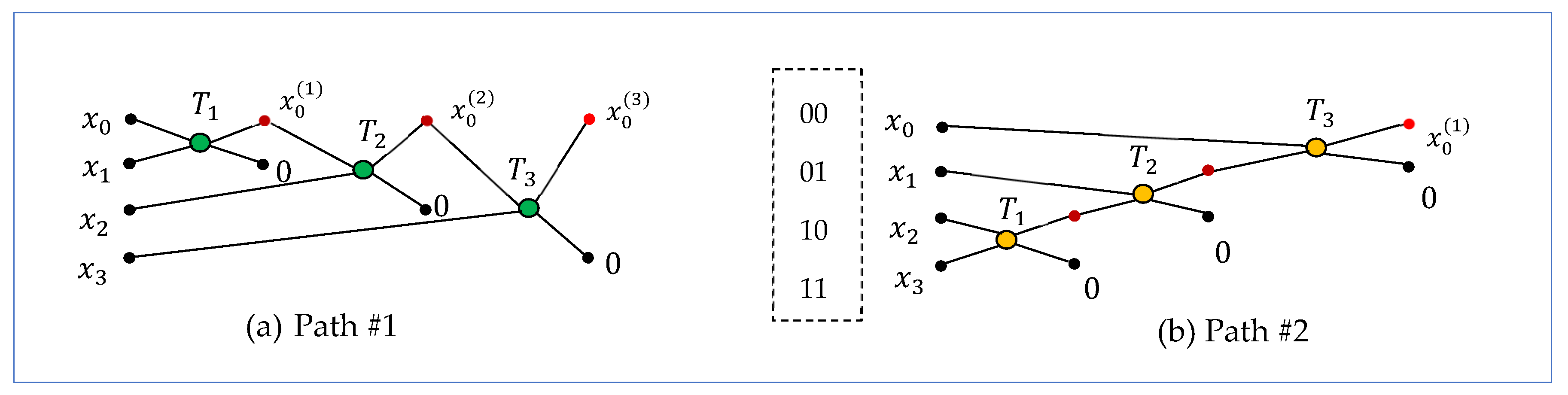
2. The Concept of the DsiHT

The N -point DsiHT is the transform that is generated by a given signal, x , of length, N . The DsiHT is defined as a transformation that moves the energy of this signal to one point; in other words, it gathers all the energy in one heap, for example, at the first point. Such a transformation can be composed, for example, from a successive set of rotations. The main characteristic of the DsiHT is the path, that is, the order in which it is assembled from the basic two-point rotations of the generator elements [35]. As example, Figure 1 shows two diagrams of composing the four-point DsiHT. Each unitary transformation, T k ,   k = 1 , 2 , 3 , is the Givens rotation, which is described as T : x , y ± x 2 + y 2 , 0 , or
T x y = cos ϑ sin ϑ sin ϑ cos ϑ x y = ± x 2 + y 2 0 .
Here, the angle is defined by the inputs as ϑ = arctan y / x , and ϑ = ± π / 2   if x = 0 . The path of the transformation, which is shown in Figure 1a, is the traditional path, and this transformation is called the DsiHT with the weak carriage-wheel (see [24] for more detail). Two rotations are on the adjacent BPs, that is, 0 and 1, and 0 and 2. The last rotation operates on BPs 0 and 3, which are not adjacent. The transform of the generator is equal to
T x = ± x , 0 , 0 , 0 = ± x 0 2 + x 1 2 + x 2 2 + x 3 2 , 0 , 0 , 0 .
The number x denotes the norm of the signal, x , that is the square root of the signal energy, E x = x 0 2 + x 1 2 + x 2 2 + x 3 2 .
The second path of the DsiHT, which is illustrated in Figure 1b, is the path of the DsiHT with the strong carriage-wheel [24]. This path also shows that one of the rotations operates on the non-adjacent BPs. These BPs are 1 (01) and 2 (10). Different rotations, T k ,   k = 1 , 2 , 3 , are used for these two DsiHTs.
Example 1. 
Consider the vector  x = ( 1 , 2 , 3 , 1 ) / 15 . The matrix of the four-point DsiHT by path #1, which is generated by the vector x , is
H 4 ; 1 = 0.2582 0.5164 0.7746 0.2582 0.8944 0.4472 0 0 0.3586 0.7171 0.5976 0 0.0690 0.1380 0.2070 0.9661 .
This matrix can be written in the integer form:
H 4 ; 1 = D 1 1 2 3 1 2 1 0 0 3 6 5 0 1 2 3 14 ,
where the diagonal matrix is D 1 = 0.2582 ,   0.4472 , 0.1195 , 0.0690 . The angles of rotations are A x ; 1 = ϑ 1 , ϑ 2 , ϑ 3 = 63.4349 ° , 53.3008 ° , 14.9632 ° .
The matrix of the four-point DsiHT by path #2, which is generated by the same vector x , is
H 4 ; 2 = 0.2582 0.5164 0.7746 0.2582 0.9661 0.1380 0.2070 0.0690 0 0.8452 0.5071 0.1690 0 0 0.3162 0.9487 .
We can also write this matrix as
H 4 ; 2 = D 2 1 2 3 1 14 2 3 1 0 5 3 1 0 0 1 3 ,
where the diagonal matrix is D 2 = 0.2582 , 0.0690 , 0.1690 , 0.3162 . The angles of rotations for this transform are A x ; 2 = 75.0368 ° ,   57.6885 ° , 18.4349 ° .
Figure 2a shows path #3 for the four-point DsiHT. All three rotations in this transform operate on the adjacent BPs. These BPs are 0 and 2, 1 and 3, and then 0 and 1. This path is considered good for building the circuit of the corresponding 2-qubit QsiHT. The quantum circuit of the transformation is shown in Figure 2b. Here, three controlled-rotation gates are used (see for detail [36]). The transform of an input signal, z, is calculated by the same diagram, as shown in Figure 2c.
The four-point DsiHT with this generator is described by the following matrix:
H 4 ; 3 = cos ϑ 3 sin ϑ 3 sin ϑ 3 cos ϑ 3 1 1 1 cos ϑ 2 sin ϑ 2 1 sin ϑ 2 cos ϑ 2 cos ϑ 1 sin ϑ 1 1 sin ϑ 1 cos ϑ 1 1
with angles A x ; 3 = { 71.5651 , 206.5651 , 35.2644 } in degrees. Therefore,
H 4 ; 3 = 1 15 1 2 3 1 0.7071 2.8284 2.1213 1.4142 3.6742 0 1.2247 0 0 1.7321 0 3.4641 .
The determinant of this matrix is equal to 1, and H 4 ; 3 x = 1 , 0 , 0 , 0 .
The 2-qubit quantum signal-induced transform (QsiDT), H 4 , is defined as the 2-qubit operation, generated by the 2-qubit superposition
| x = 1 x x 0 | 00 + x 1 | 01 + x 2 | 10 + x 3 | 11 ,                                                          
such that H 4 | x = | 00 . The transform is composed of three rotations with angles of A x , and with the same path as its discrete analog DsiHT uses.
Figure 3 shows the circuit for the transformation of the 2-qubit superposition:
H 4 ; 3 : | x = 1 15 | 00 2 | 01 + 3 | 10 + | 11 | 00 .
Table 1 shows the difference between the above 2-qubit QsiHTs. The QsiHT by the first two paths have one rotation on nonadjacent planes each. That requires one permutation of planes 2 and 1 for path #1, and the permutations of planes 2 and 3 for path #2, which is CNOT operation.
Thus, the above three three-point DsiHTs, H 4 , use different sets of angles A x = { ϑ 1 ,   ϑ 2 , ϑ 3 } , which are calculated from the same generator, x = ( x 0 , x 1 , x 2 , x 3 ) . The results of the calculations are the same (up to the sign):
H 4 x = x 0 ( k ) , 0 , 0 , 0 = ± x 0 2 + x 1 2 + x 2 2 + x 3 2 , 0 , 0 , 0 ,   k = 3 , 1 , 2
The DsiHT with path #3 is considered more effective than paths #1 and #2. The generated transform operates on an input of z = ( z 0 , z 1 , z 2 , z 3 ) , using the same path, as shown in Figure 2c,
H 4 z = z 0 ( 2 ) , z 1 ( 1 ) , z 2 ( 1 ) , z 3 ( 1 ) .
Such effective paths exist for the N -point DsiHTs when N > 2 , and the larger this number, N , the more such paths can be found. We call them the fast paths since they do not require addition permutations of basis states.
To evaluate and simulate the proposed quantum algorithms in this paper, the Qiskit Framework (version 1.3.2) is used [37]. However, any quantum simulation framework can be used. Qiskit was chosen since the Qiskit framework is an open-source quantum computing framework developed by IBM Quantum that provides the ability to design, simulate, and execute quantum circuits. Qiskit provides various tools for creating quantum circuits, modeling noise, and access to actual quantum hardware through IBM Quantum’s cloud backends [36]. The probabilities of the quantum scheme shown in Figure 3 are given in Table 2, when the transform is applied to a random normalized superposition state given by | x = 1 , 2 , 3 , 1 / 15 for 1 thousand, 10 thousand, 100 thousand, and 1 million shots.

3. DsiHT-Based QR Decomposition

In this work, we describe the QR decomposition of a square matrix, A , of size 2 r × 2 r ,   r > 1 by the Givens rotations. The unitary matrix, A , is considered with real coefficients. In the QR decomposition of matrix A , ( 2 r 1 ) DsiHTs are used [34]. Matrix A is transformed sequentially into a diagonal matrix. Each of these DsiHTs moves the energy of the columns of the matrix into the diagonal, R . This decomposition is illustrated below for a 4 × 4 unitary matrix:
A = :   D s i H T A 1 = 0 0 0 0 0 0 :   D s i H T A 2 = 0 0 0 0 0 0 0 0 0 0 :   D s i H T R = 0 0 0 0 0 0 0 0 * 0 0 0 0 .
The first DsiHT is generated by the first column, x 1 , of matrix A , and it will be changed as x 1 ± x 1 , 0 , 0 , 0 . After multiplying the matrix of this DsiHT by matrix A , the new matrix, A 1 , will contain six zero coefficients, as shown above. The same process is repeated to the 3 × 3 submatrix of matrix A 1 . Namely, the second three-point DsiHT is generated by the three components of the second column of matrix A 1 . This transform is applied to the 3 × 3 sub-matrix and another four zero coefficients will be obtained in the new matrix, A 2 . The block diagram of this transform and its quantum circuit are both shown in Figure 4a. The last two-point DsiHT is generated by the last two coefficients of the third column of A 2 and is applied to its 2 ×   2 sub-matrix. This transform and its circuit are given in part Figure 4b. Thus, the matrix diagonalization is complete. Matrix R is diagonal, with the coefficients ± 1 on the diagonal. When processing this matrix in quantum computation, each of the above DsiHTs is the 2-qubit QsiHT generated by the full column of matrix A , A 1 , or A 2 . For instance, the second QsiHT will be generated by the second column (written as a 2-qubit superposition) of matrix A 1 . Therefore, this transform is not described by the matrix of type 1 H 3 , where H 3 is the matrix of the three-point DsiHT. One can note from Figure 2 and Figure 3 that the QR decomposition of matrix A uses six rotation gates and has a depth of 4 . It also means that 2-qubit operations can be calculated by only six rotations.
Now, we consider a square unitary matrix, A , of size 8 × 8 , with determinant det A 0 . For this matrix, seven DsiHTs with different paths are used. In the first step, the eight-point DsiHT is generated by the first column of A . We change the notation of matrix H 8 of this transform by H 0 7 . The subscript indicates the bit planes on which the transform operates. In the second step of the calculations, the seven-point DsiHT is generated by the vector that is equal not to the full second column of the new matrix, H 0 7 A , but to the reading from the second row. The first row and column of the H 0 7 A matrix will remain unchanged in subsequent calculations. Thus, the seven-point DsiHT operates on the bit planes 1–7, not 0–6. We denote the matrix of this transformation as H 1 7 . In the next step of the decomposition, the six-point DsiHT is generated by the columns number, three, of the new matrix H 1 7 ( H 0 7 A ) , but to the reading from the third row. This six-point DsiHT with matrix H 2 7 operates on the bit planes 2–7, and so on. The last DsiHT operates on the bit planes 6 and 7, and its matrix is denoted as H 6 7 . In quantum computing, it is important to remember the location of these generators for the next rotations.
The block diagram of the decomposition of the 8 × 8 matrix, A , is shown in Figure 5. According to the described QR decomposition, or the operation triangularization (factorization), it is fulfilled by seven DsiHTs,
T :   A R = H 6 7 H 5 7 H 4 7 H 3 7 H 2 7 H 1 7 H 0 7 A .
Here, matrix R is an upper triangular matrix. If matrix A is unitary and real, matrix R is a diagonal matrix with the coefficients ± 1 on the diagonal. If R is the identity matrix, the factorization, T , describes the decomposition of the inverse operation, A 1 .
The block diagram of the calculation of operation A is shown in Figure 6,
A = T 1 ( R ) = H 6 7 H 5 7 H 4 7 H 3 7 H 2 7 H 1 7 H 0 7 R = H 0 7 H 1 7 H 2 7 H 3 7 H 4 7 H 5 7 H 6 7 R .
Here, all matrices, H k 7 ,   k 0 : 6 , are unitary, and H k 7 denotes the matrix transpose to H k 7 , k { 0 , 1 , , 6 } . The numbers of controlled-rotation gates are also shown for each of the transforms. A maximum of 28 rotation gates are used for operation A on a 3-qubit superposition. Each rotation in this diagram is performed by the single controlled-rotation gate on the corresponding pair of adjacent bit planes.
Now, we will describe each step of the decomposition in detail for 3-qubit operations. Then, the 3-qubit quantum Hartley transform and cosine transforms of types II and IV will be analyzed.
A. The case N = 8 (transform H 0 7 ): The block diagram of the eight-point DsiHT, H 0 7 , with the fast path is shown in Figure 7. The outputs with the open circles in this diagram are zero.
The corresponding circuit for the 3-qubit QsiHT with seven controlled gates of rotations is given in Figure 8. The matrices of rotations are defined by
R ϑ k = W ϑ k = cos ϑ k sin ϑ k sin ϑ k cos ϑ k ,         k = 1 : 7 .
This transform generated by the first column of A is used in the first step in the QR decomposition of the 8 × 8-square matrix, A A 1 = H 0 7 A . Next, we describe six other required transforms with the corresponding diagrams and quantum circuits.
B. The case N = 7 (transform H 1 7 ): The input is the 3-qubit superposition in the form of x 1 = ( a , x 1 , ,   x 7 ) , and the transform keeps the first amplitude, a , unchanged. This superposition corresponds to the second column of the matrix A 1 . The block diagram of this eight-point DsiHT is shown in Figure 9. Before rotating the data, the CNOT gate is used to move the component x 1 to the 0-bit plane, to have all rotations on the bit planes which differ only in one bit. The fourth rotation operates on bit planes 0 (000) and 2 (010). It could not operate on bit planes 1 (001) and 2 (010). One CNOT gate is also used at the end of calculations to move amplitude, a , back to bit plane 0. Thus, this transform requires six elementary rotations and two CNOT gates. This transformation is applied to A 1 to obtain the matrix A 2 = H 1 7 A 1 . It should be noted that the path of the DsiHT shown in this diagram is only one of the possible ones. There are other ways to process this vector. This path seems simple and the difference with the eight-point DsiHT with the fast path is small.
The corresponding quantum circuit for this transformation is given in Figure 10. Six controlled-rotation gates and two CNOT operations are used in this circuit.
Now, we consider another path for this transformation, which uses only six rotations with a distinct set of angles. The diagram of the DsiHT with this path is shown in Figure 11.
The quantum circuit for the 3-qubit QsiHT with this new path is given in Figure 12. This circuit does not use the X gate.
Rotation number 1 (or 2 and 5) operates on an input ( x , y ) as follows:
R ϑ 4 x y = cos ϑ 4 sin ϑ 4 sin ϑ 4 cos ϑ 4 x y = 0 ± x 2 + y 2 ,             ϑ 4 = atan x y .
Here, the property atan ( x / y ) +   atan ( y / x ) = π / 2 can be used and the Givens rotation can be considered,
R φ 4 x y = cos φ 4 sin φ 4 sin φ 4 cos φ 4 x y = ± x 2 + y 2 0 , φ 4 = atan y x .
Then, instead of the matrix R ϑ 4 , we can use R φ 4 + π / 2   or R φ 4 π / 2   on the same input x , y , to get the result in Equation (18).
Example 2. 
Consider the input x , y = 3 , 4 .   Then,
R φ x y = cos φ sin φ sin φ cos φ 3 4 = 0.6 0.8 0.8 0.6 3 4 = 5 0 , φ = atan 4 3 = 53.1301 ° .
For the angle ϑ = φ + 90 ° = 143.1301 ° , we obtain
R ϑ x y = cos ϑ sin ϑ sin ϑ cos ϑ 3 4 = 0.8 0.6 0.6 0.8 3 4 = 0 5 , ϑ = atan 3 4 .
C. The case N = 6 (transform H 2 7 ): The input is the 3-qubit superposition in the form of x 1 = ( a , b ,   x 2 , ,   x 7 ) , and the transform keeps the first two amplitudes, a and b , unchanged. The block diagram of this eight-point DsiHT is shown in Figure 13. After the fourth rotation, the next rotation operates on bit planes 2 (010) and 6 (110).
The quantum circuit for transform H 2 7 is given in Figure 14. Five controlled-rotation gates are used in this circuit. After applying this transform on matrix A 2 , in this stage of the QR factorization, we obtain the new matrix, A 3 = H 2 7 A 2 .
D. The case N = 5 (transform H 3 7 ): The input is the 3-qubit superposition in the form of x 1 = ( a , b , c ,   x 3 , ,   x 7 ) , and the transform keeps the first three amplitudes, a , b , and c, unchanged. The block diagram of the 3-qubit QsiHT and its circuit are shown in Figure 15. Four controlled gates of rotations are required for this case. At this stage of QR factorization, we obtain the new matrix, A 4 = H 3 7 A 3 .
E. The case N = 4 (transform H 4 7 ): The input is the 3-qubit superposition in the form of x 1 = ( a , b , c ,   d , x 4 , ,   x 7 ) , and the transform keeps the first half of the input unchanged. The block diagram of this 3-qubit QsiHT is shown in Figure 16. The quantum circuit for this transformation is also given in this figure. At this stage of QR factorization, we obtain the matrix A 5 = H 4 7 A 4 .
F. The case N = 3 (transform H 5 7 ): The input is the 3-qubit superposition in the form of x 1 = ( a , b , c ,   d , e , x 5 , x 6 ,   x 7 ) , and the transform processes only the last three amplitudes. The block diagram of this 3-qubit QsiHT is shown in Figure 17. Two rotations operate on bit planes 6 (110) and 7 (111), and then on 5 (101) and 7 (111). The quantum circuit for this transformation is also given in this figure. After applying this transform on A 5 , we obtain the matrix A 6 = H 5 7 A 5 .
G. The case N = 2 (transform H 6 7 ): The input is the 3-qubit superposition in the form of x 1 = ( a , b , c , d , e , f , x 6 ,   x 7 ) , and the transform processes only the last two amplitudes. The block diagram of this QsiHT is shown in Figure 18, together with the corresponding controlled-rotation gate. This transform describes the last stage of QR factorization with the matrix, A 7 = H 6 7 A 6 .
All seven DsiHTs described above are used in the QR decomposition of the 8 × 8-matrix, A = Q R . Namely, these seven transforms are used for calculating the matrix, T A = R . Matrix R is diagonal. Thus, to calculate matrix R , the number of 2-bit controlled-rotation gates is equal to
μ r = 7 + 6 + 5 + + 1 = ( 8 × 7 ) / 2 = 28 .
These are the numbers of elementary gates for the triangularization of any 3-qubit gate. The diagonal matrix, R , in this decomposition should be considered separately because it is different for different matrices, A .

3.1. Three-Qubit Gate Circuits

Now, we can put together all seven circuit elements described above to build a quantum circuit for computing the 3-qubit operation with the triangular matrix, R . Figure 19 shows the circuit for the matrix factorization, T :   A R . It should be noted that this circuit can be used for any operation described by the square matrix 8 × 8 with nonzero determinant. In the above case, operation A is unitary, and matrix R is diagonal with coefficients ± 1 on the diagonal. To simplify the notations in the circuit, we use the same notations for angles on the different stages of decompositions; that is, for transforms H k 7 ,   k = 0 : 6 . For instance, the notation ϑ 1 presents the different angles for each of these transforms. It must be noted that A 1 = A = R T = R T . Thus, we add the diagonal gate, R , to the end of this circuit, and we obtain the quantum circuit for the inverse operation, A 1 .

3.2. Inverse Transform and 3-Qubit Gate Circuit

By using the QR decomposition of a unitary matrix by the QsiHTs, T A = R , the unitary operation, A , on the 3-qubit superposition can be written as
A = T 1 R = Q R = H 0 7 H 1 7 H 2 7 H 3 7 H 4 7 H 5 7 H 6 7 R .
After inverting all circuit elements of seven QsiHTs in the circuit in Figure 19, we obtain the quantum circuit for operation A , which is given in Figure 20. This is the general circuit to implement any 3-qubit unitary operation with a real matrix. A maximum of 28 control rotations are needed to calculate the 3-qubit operation, A . All rotations are fulfilled on the adjacent bit planes. The depth of the circuit is equal to 18. This circuit does not use any permutation elements or CNOT gates, but only rotation gates as shown in Table 3.

4. Examples of the QR Decomposition-Based Quantum Transforms

In this section, we consider the eight-point discrete Hartley transform (DHyT) and its analogue, the 3-qubit quantum Hartley transform (QHyT). The 3-qubit DCT-II and DCT-IV are also described.

4.1. Quantum Hartley Transform

In the N -point DHyT, the basis functions ψ p n = cos ( 2 π n p / N ) + sin ( 2 π n p / N ) are used instead of complex exponential basis φ p n = cos ( 2 π n p / N ) + i sin ( 2 π n p / N ) in the DFT [23]. Therefore, the transform is real. The eight-point DHyT of a signal x n is calculated by
X p = 1 8 n = 0 7 x n cos 2 π 8 n p + sin 2 π 8 n p ,               p = 0 , 1 , , 7 .
The matrix of the eight-point transform is equal to
A = a n , m n , p = 0 : 7 = 1 8 cos π 4 n p + sin π 4 n p n , p = 0 : 7 .                  
The 3-qubit quantum Hartley transform (QHyT) of the 3-qubit quantum superposition | x = x 0 | 000 + x 1 | 001 + + x 7 | 111 is defined as
| A ( x ) = X 0 | 000 + X 1 | 001 + X 2 | 010 + + X 7 | 111 .
In the QR decomposition by the QsiHTs, matrix A is transformed into the diagonal matrix,
T : A R = ( H 6 7 H 5 7 H 4 7 H 3 7 H 2 7 H 1 7 H 0 7 ) A = d i a g { 1 , 1 , 1 , 1 , 1 , 1 , 1 , 1 } .
This diagonal matrix is R = I 4 I 2 Z , where Z is the Pauli Z-rotation gate 1   0 ; 0 , 1 . The angles for all rotations in this transformation are given in Table 4. Here, the symbol denotes the direct sum, or the Kronecker sum, of matrices.
We can note that many angles are 45 ° . The operations of rotation by the angles of 0 ° , 90 ° , 180 ° , 270 ° , 135 ° , and 225 ° are described by the following matrices:
R 45 ° = 1 2 1 1 1 1 = 1 0 0 1 1 2 1 1 1 1 = Z H 2 ,       H 2 = 1 2 1 1 1 1 ,
R 225 ° = R 45 ° ,   R 135 ° = R 45 ° = H 2 X , R 90 ° = 0 1 1 0 ,   R 180 ° = 1 0 0 1 ,   R 270 ° = 0 1 1 0 .
where H 2 is the Hadamard matrix. Therefore, the circuit in Figure 19 for the QHyT decomposition can be simplified, as shown in Figure 21. The number of controlled-rotation gates is 21 plus 1 local gate of rotation in this circuit. The rotation gate H 6 7 is the identity operation. The controlled Pauli Z -rotation is also shown in this figure. If we connect this gate to the circuit, we obtain the quantum circuit of the inverse 3-qubit Hartley transform. The matrix of this inverse transform can be written as
A 1 = A = ( I 4 I 2 Z ) ( H 6 7 H 5 7 H 4 7 H 3 7 H 2 7 H 1 7 H 0 7 ) .
Figure 22 shows the grayscale images of matrix A , together with matrices H k 7 ,   k = 0 : 6 , and the matrix Q in Figure 22a. These images illustrate the process of QR decomposition of the DHyT matrix. The images, X , are displayed as 128 ( X + 1 ) . Matrix R is not the identity matrix. Therefore, the last column of matrix Q differs from the last column of matrix A . All required angles of rotation in Table 4 are shown on the unit circle in Figure 22b.
The matrix of the 3-qubit DHyT can be written as
A = Q R = H 0 7 H 1 7 H 2 7 H 3 7 H 4 7 H 5 7 ( I 4 I 2 Z ) .
The quantum circuit for the 3-qubit QHyT is given in Figure 23. The angles are φ k = ϑ k and H φ k = H ϑ k for k = 1 : 7 . The set of angles, φ k , is given in Table 5. In the beginning of this circuit, the controlled Pauly Z gate is used for the diagonal matrix, R = I 4 I 2 Z .
We can see from Table 5 that there are a few simple rotations,
R 45 ° = 1 2 1 1 1 1 ,   R 135 ° = R 45 ° ,   R 225 ° = R 135 ° = 1 2 1 1 1 1 = H 2 ,
  R 270 ° = 0 1 1 0 ,       A 2 = 1 2 1 1 1 1 .      
In the circuit of the 3-qubit QHyT, 21 controlled rotations and 1 local rotation are used, plus the controlled Z gate. The depth of the circuit is equal to 15 (in Table 6).

4.2. The Quantum Cosine Transforms

In this section, we consider a discrete cosine transform (DCT) which is widely used in signal processing, especially in data compression. This real transform is used in different definitions. We describe the QR decomposition of DCTs of type II and type IV.
A. The eight-point DCT-II of a signal x n ,   n = 0 : 7 , is calculated by [20,27]
X p = 1 2 n = 0 7 x n cos π 8 ( n + 0.5 ) p ,       X 0 = X 0 1 2 ,       p = 0 , 1 , , 7 .
The matrix of the eight-point transform can be written as
A = 1 2 d i a g 1 / 2 , 1 , 1 , , 1 cos π 8 n + 0.5 p n , p = 0 : 7 , det A = 1 .
The 3-qubit quantum cosine transformation of type II (QCT-II) is defined as the operation
| x = n = 0 7 x n | n | A ( x ) = p = 0 7 X p | p .
where | n and | p are the computation basis states in the space of 3 qubits.
The QR decomposition of this matrix by the DsiHTs results in the identity matrix:
T :   A R = ( H 6 7 H 5 7 H 4 7 H 3 7 H 2 7 H 1 7 H 0 7 )   A = d i a g 1 , 1 , 1 , 1 , 1 , 1 , 1 , 1 .
Therefore, the inverse DCT-II is A 1 = A = H 6 7 H 5 7 H 4 7 H 3 7 H 2 7 H 1 7 H 0 7 and
A = Q = H 0 7 H 1 7 H 2 7 H 3 7 H 4 7 H 5 7 H 6 7 .
The rotation angles in this decomposition are given in Table 7. All twenty-eight angles are different, and it is impossible to know if the circuit in Figure 20 can be simplified for the QCT-II.
For comparison, we consider the quantum circuit design (QCD) of the 3-qubit QCT-I using its fast computation flow graph [26]. The number of gates and depth of two methods are given in Table 8.
B. The eight-point DCT-IV of a signal x n ,   n = 0 : 7 , is calculated by [27]
X p = 1 8   n = 0 N 1 x n cos π 8 ( n + 0.5 ) ( p + 0.5 ) ,                     p = 0 , 1 , , 7 .
The matrix of the eight-point transform can be written as
A = 1 8 cos π 8 n + 0.5 ( p + 0.5 ) n , p = 0 : 7 ,   det A = 1 .
The quantum analog, that is, the QCT-IV, of the DCT-IV is defined as in Equation (34). Unlike the DCT-II, the matrix of the DCT-IV is symmetric. Therefore, matrix A 1 = A = A ; that is, A 2 = I 8 . The QR decomposition of matrix A by the DsiHTs results in the identity matrix, as in the case of the DCT-II; that is, Equation (35) holds for the DCT-IV. The angles of rotation in this decomposition are given in Table 9.
Figure 24 shows the grayscale images of matrix A of the DCT-II in Figure 24a. The image of X is displayed as 128 ( X + 1 ) . All required angles of rotations in Table 7 are shown on the unit circle in Figure 24b. The matrix of the DCT-IV as a grayscale image is shown in Figure 24c, and all angles, ϑ k , of the DsiHTs in the QR decomposition of this transform (from Table 9) are shown in Figure 24d.

4.3. Three-Qubit Real Unitary Gate

The circuits in Figure 19 can be used to generate any 3-qubit real unitary operation. For that, we only need to fill Table 10 with 28 angles and choose a diagonal matrix, R , with coefficients ± 1 . The unitary transform is calculated as
A = H 0 7 H 1 7 H 2 7 H 3 7 H 4 7 H 5 7 H 6 7 R .
If, among these angles, there are angles of 0 ° , and ± 90 ° , 180 ° , and 27 0 ° , then the above circuit can be simplified.
The angles of Table 10 were generated randomly by the following function, using MATLAB R2024b:
% -----------------------------------------------------------------------
% call: key_angles3Q.m
% Artyom M. Grigoryan, EE UTSA, February 7, 2025
 function [U1,U2,U3,U4,U5,U6,U7]=key_angles3Q
         p2=2*pi;
         U1 = -pi+p2.*rand(1,7);
         U2 = -pi+p2.*rand(1,6);
         U3 = -pi+p2.*rand(1,5);
         U4 = -pi+p2.*rand(1,4);
         U5 = -pi+p2.*rand(1,3);
         U6 = -pi+p2.*rand(1,2);
         U7 = -pi+p2.*rand;
 end
% -----------------------------------------------------------------------
  • and the diagonal matrix by the commands:
% Diagonal matrix diag{1,1,1,1,1,1,1, -1, or 1}.
      R=eye(8); r=rand;
      if r<0.5
          R(8,8)=-1;
      end
% -----------------------------------------------------------------------
This set of angles with the diagonal matrix R = I 8 defines the 3-qubit unitary operation with the following unitary matrix (with the determinant equal to 1):
0.0475 0.8332 0.3004 0.2381 0.2182 0.1212 0.2694 0.1472 0.1102 0.4434 0.5928 0.1126 0.0978 0.5086 0.0687 0.3928 0.1092 0.1079 0.5645 0.2071 0.6875 0.0839 0.0340 0.3661 0.0734 0.1707 0.0255 0.9244 0.2328 0.1969 0.0843 0.1005 0.5620 0.1208 0.3809 0.0009 0.3992 0.5425 0.0925 0.2495 0.5762 0.0814 0.1823 0.0528 0.4955 0.1925 0.0668 0.5816 0.4842 0.0645 0.2438 0.0031 0.0527 0.4511 0.4962 0.4994 0.2931 0.2074 0.0367 0.1741 0.0910 0.3821 0.8094 0.1732 .
Different 3-qubit unitary transformations, or gates, differ in the table of angles. In other words, the above table of 28 angles is the key characteristic of the 3-qubit gate. We call this table the table of keys of the gate. The same for n -qubit gates, where n > 2 . For 4-qubit gates, the number of such angles in the table of keys is 120, and 2 n 1 ( 2 n 1 ) in the general case. The main advantages of the proposed QR decomposition by the DsiHT with fast paths are as follows:
  • It does not require any permutations, including CNOT operations, for any unitary gate in the quantum computation,
  • Only the Given rotations are gates required to perform the operation with unitary real matrix,
  • It gives us a simple (transparent) calculation quantum circuit,
  • It generates a unique table of keys.

4.4. Simulations in Qiskit

To validate the correctness and practical implementation of the proposed 3-qubit quantum transforms, QHyT, QCT-II, and QCT-IV, each circuit was implemented using the Qiskit framework, with their codes available at https://ceid.utsa.edu/agrigoryan/. Simulations were conducted across various shot counts (1000, 10,000, 100,000, and 1,000,000), measuring how closely the experimentally obtained quantum state distributions matched their theoretical counterparts. Specifically, the analysis focused on probability distributions, state amplitudes, and mean squared relative error (MSRE) for each configuration. The results are summarized in the following tables and are visually graphed in their corresponding figures.
Each transform is represented by two key simulation tables. The first table reports the output probability distribution resulting from the quantum scheme applied to a standard input (the 000 initial state). This captures the transform’s native behavior and how the basis states are redistributed by the algorithm. The second table presents the corresponding amplitude distribution when the transform is applied to a random normalized superposition state given by | x = 2 , 7 , 3 , 9 , 8 , 6 , 5 , 1 / 269 .
The quantum Hartley transform is characterized by a uniform theoretical probability distribution across all basis states. Each of the eight basis states is expected to have a probability of 0.125 (in Table A1). This theoretical uniformity is largely preserved in simulations. At low shot counts (around 1000 shots), deviations from uniformity are noticeable. However, as the number of shots increases, these fluctuations diminish, and the empirical distribution approaches the ideal states. Moreover, the MSRE decreases from 3.24 × 10 3 at 1000 shots to just 7.75 × 10 5 at 1,000,000 shots.
The amplitude analysis for QHyT using the normalized input superposition previously mentioned further supports the simulation’s accuracy. The expected dominant amplitude for state 000 is 0.8838, and this behavior is preserved across all shot counts. Minor deviations in less dominant states remain within acceptable bounds. The corresponding MSRE drops from 4.39 × 10 3 at 1000 shots to 1.20 × 10 4 at 1,000,000 shots (in Table A2). Figure A1 demonstrates this graphically, with a strong overlap between theoretical and sampled bars for all states.
Unlike QHyT, the 3-qubit quantum cosine transform II (QCT-II) features a non-uniform theoretical probability distribution. Certain states, such as 001 and 010 , dominate the distribution, and this non-uniformity is captured in the simulations. Even at low shot counts, dominant states retain relatively higher probabilities. For example, 001 stabilizes to 0.2409 at 1,000,000 shots, which is close to the theoretical 0.2405 (in Table A3). Low-probability states also match well, and the MSRE improves from 2.78 × 10 3 to 1.52 × 10 4 .
Table A4 for QCT-II presents the amplitude results using the normalized superposition input. Amplitude values show a strong peak at | 101 = 0.7869 and significant values at | 111 = 0.5153 . Simulated amplitudes align closely with these values, even at lower shot counts. Near-zero amplitude states are also accurately captured. The MSRE decreases from 4.41 × 10 3 at 1000 shots to 5.36 × 10 5 at 1,000,000 shots. Figure A2 supports this visually.
QCT-IV presents a more complex distribution due to the theoretical probabilities ranging from 0.0024 ( | 111 ) to 0.2476 ( | 000 ) (see Table A5). These are still effectively reproduced in the simulations. As expected for low shot counts, larger deviations are observed, but at 100,000 shots, the probabilities closely resemble theoretical values. MSRE improves from 3.38 × 10⁻² to 1.28 × 10⁻⁴. As with the previous quantum schemes, QCT-IV is also evaluated using the normalized superposition input. The dominant amplitude at | 000 = 0.8458 remains consistent, and low-amplitude states like | 100 are properly minimized. The MSRE drops from 3.92 × 10 2 to 1.04 × 10 4 (in Table A6).
The following trend emerges across all the transforms:
  • Increasing shot count improves convergence and lowers MSRE.
  • Complicated transforms like the QCT-IV show more initial variance but stabilize with enough shots.
  • Amplitudes, both large and small, are consistently and accurately recovered.
Figure A3 demonstrates the comparison between theoretical and sampled bars for all states for the 3-qubit QCT-IV.
In general, the Qiskit simulations provide strong empirical support for the fidelity of QHyT, QCT-II, and QCT-IV. As shot counts increase, both probabilities and amplitudes converge to their theoretical values. Visual comparisons in the figures show near-perfect agreement at 10,000 and 100,000 shots. These results confirm that using the QsiHT for the construction of the transforms is reliable.

5. Application of the QsiHT for Preparing Dicke States

In this section we once again draw attention to the importance of choosing the right path for efficient computation of quantum operations. Here, we focus on the 3-qubit operations. As shown in Figure 6, the 3-qubit QsiHT with the fast path is calculated in three stages; in other words, its quantum circuit with seven rotation gates in Figure 7 has a depth of 3. For special classes of quantum superpositions, the number of rotation gates can be reduced. As an example, we consider the 3-qubit DsiHT generated by Dicke state, which is the equal superposition of all 3-qubit basis states with Hamming weight 2 [38],
| D 2 3 = 1 3 | 011 + | 101 + | 110 .
The corresponding 3-qubit QsiHT with fast path, or the eight-point DsiHT generated by the vector x = ( 0 , 0 , 0 , 1 , 0 , 1 , 1 , 0 ) / 3 ,   can be used. In this case, two rotation gates in stage 1 are identity operations; that is, ϑ 1 = ϑ 4 = 0 . Therefore, the 3-qubit QsiHT uses only five rotation gates. Figure 25 shows the block diagram of the simplified diagram of Figure 7. This transform can be used for any 3-qubit superposition of type | x = a 1 | 011 + a 2 | 101 + a 3 | 110 , with the real coefficients under the condition that a 1 2 + a 2 2 + a 3 2 = 1 .
The corresponding quantum circuit for this transform is shown in Figure 26. The five angles of the rotations are 90 ° , 90 ° , 45 ° , 54.7356 ° , 90 ° . The matrices of the rotations are
R 90 ° = 0 1 1 0 ,   R 45 ° = 1 2 1 1 1 1 ,   R 54.7356 ° = 0.5774 0.8165 0.8165 0.5774 .
For the input | z = | D 2 3 , the result of calculation is H 8 | D 2 3 = | 000 . The circuit for the inverse operation is given in Figure 27. This circuit can be used for the Dicke state preparation.
H 8 = 0 0 1 0 0 0 0 0 0 1 0 0 0 0 0 0 0 0 0 1 0 0 0 0 0.5774 0 0 0 0.8165 0 0 0 0 0 0 0 0 1 0 0 0.5774 0 0 0 0.4082 0 0.7071 0 0.5774 0 0 0 0.4082 0 0.7071 0 0 0 0 0 0 0 0 1 ,       H 8 | 000 = | D 2 3 .
We can also consider other paths for the QsiHT generated by the same 3-qubit superposition, | x , or Dicke state. As an example, Figure 28 shows such a path.
In the DsiHT with this path, the angles of the rotations are ϑ k ; k = 1 : 5 = 90 ° , 45 ° , 54.7356 ° , 90 ° , 90 ° . The corresponding matrices of rotations are
R 90 ° = 0 1 1 0 ,   R 45 ° = 1 2 1 1 1 1 ,   R 54.7356 ° = 0.5774 0.8165 0.8165 0.5774 ,   R 90 ° = 0 1 1 0 .
The quantum circuit for this 3-qubit QsiHT is shown in Figure 29.
The quantum circuit for the inverse 3-qubit QsiHT is given in Figure 30. This circuit for the preparation of the Dicke state, | D 2 3 , also uses five gates of rotation.
The matrix of the rotation, R 45 ° , is the Walsh–Hadamard matrix. In the matrix form, this circuit is described as
H 8 = 0 0 1 0 0 0 0 0 0 1 0 0 0 0 0 0 0 0 0 1 0 0 0 0 0.5774 0 0 0 0 0 0 0.8165 0 0 0 0 1 0 0 0 0.5774 0 0 0 0 0.7071 0 0.4082 0.5774 0 0 0 0 0.7071 0 0.4082 0 0 0 0 0 0 1 0 ,       H 8 | 000 = | D 2 3 .
The depth of the second circuit is equal to 5, and the circuit in Figure 27 has a depth equal to 3. The number of rotation gates for both circuits is the same, five.
In the general case, when n 2 , the n -qubit QsiHT with the fast path is described by a block diagram like the one in Figure 7. The quantum circuits for this transform, and inverse operation have depth n and use ( 2 n 1 ) rotation gates each. It also means that the Dicke state, | D k n , where k < n , can be prepared by the n -qubit QsiHT, H 2 n | D k n = | 0 n , with the quantum circuit with depth n and using less than ( 2 n 1 ) rotation gates. As reported in [38], the known deterministic algorithm for preparing the Dicke state uses O ( k n ) gates and has depth O ( n ) . Similar estimates can be analyzed and compared for other special cases of quantum-state preparation [39,40,41].

6. Conclusions

In this work, we describe in detail the general method of QsiHT-based QR decomposition for unitary operations. The quantum circuits for implementing unitary operations on three-qubit superpositions are presented. The DsiHT is used with path which allows us to accomplish the QR decomposition of the unitary matrix only by rotations with one parameter. Such a path is called the fast path of the QsiHT. No permutations with Gray codes and CNOT gates are used in the proposed methods. As examples, the quantum cosine transforms of types II and IV, and the quantum Hartley transforms are described. The presented method can also be used to construct quantum circuits for n -qubit operations, when n > 3 , since the fast paths with splitting for n -qubit DsiHTs can also be found. The case of a unitary operation with real matrices is considered.
The presented method can be extended to the unitary operations with complex matrices, A , by adding the phase gates to the rotations in the described QR decomposition by the DsiHT. Such DsiHTs are called complex DsiHTs, and three complex matrix decompositions by such transformations are described by Grigoryan in [34,42]. Although the present work focuses on qubits of size n = 3 , the DsiHT-based QR decomposition can be generalized to larger qubit registers. As noted in Section 3.2, an n -qubit QsiHT along a “fast path” yields a circuit of depth n using exactly 4 n / 2 2 n 1 controlled-rotation gates, and zero permutations and CNOTs.
In future works, we plan to present a universal methodology to generate any n -qubit QsiHT-based QR-decomposition circuits beyond 3 qubits by developing automated layer-selection algorithms for the n -qubit QsiHT, evaluating depth-width trade-offs, and benchmarking such qubit decompositions in both Qiskit and IBM’s quantum hardware. Through IBM’s quantum hardware, we plan to translate our QsiHT circuits to incorporate qubit-connectivity constraints and perform resource estimates such as circuit depth and n -qubit error budgets to guide experimental implementation. Based on the results of the experimental implementation, we plan to integrate zero-noise extrapolation and Pauli-twirling techniques to characterize noise and minimize coherent errors.

Author Contributions

Conceptualization, A.M.G.; methodology, A.M.G.; software, A.M.G., A.G. and I.E.; validation, A.M.G. and A.G.; formal analysis, A.M.G., A.G. and S.S.A.; investigation, A.M.G.; resources, A.M.G. and A.G.; data curation, A.M.G. and A.G.; writing—original draft preparation, A.M.G., writing—review and editing, A.M.G., A.G. and S.S.A.; visualization, A.M.G., A.G. and S.S.A.; supervision, A.M.G.; project administration, A.M.G.; funding acquisition, A.M.G. All authors have read and agreed to the published version of the manuscript.

Funding

This research received no external funding.

Institutional Review Board Statement

Not applicable.

Informed Consent Statement

Not applicable.

Data Availability Statement

The authors agree to share their data publicity, so supporting data will be available.

Conflicts of Interest

The authors declare no conflicts of interest.

Abbreviations

The following abbreviations are used in this manuscript:
DsiHTDiscrete signal-induced Heap transform
QsiHTQuantum signal-induced Heap transform
QRQR decomposition of the matrix
DCTDiscrete cosine transform
QCTQuantum cosine transform
DHyTDiscrete Hartley transform
QHyTQuantum Hartley transform
MSREMean square root error
BPBit plane

Appendix A

Table A1. Probabilities for the 3-qubit QHyT in Qiskit.
Basis
States
Probabilities
Theoretical1000 Shots10,000 Shots100,000 Shots1,000,000 Shots
0001.2500 × 10−1 1.1900 × 10⁻¹ 1.2870 × 10⁻¹ 1.2510 × 10⁻¹ 1.2485 × 10⁻¹
0011.2500 × 10−1 1.1900 × 10⁻¹ 1.2100 × 10⁻¹ 1.2470 × 10⁻¹ 1.2538 × 10⁻¹
0101.2500 × 10−1 1.2200 × 10⁻¹ 1.2760 × 10⁻¹ 1.2546 × 10⁻¹ 1.2463 × 10⁻¹
0111.2500 × 10−1 1.2300 × 10⁻¹ 1.2660 × 10⁻¹ 1.2465 × 10⁻¹ 1.2510 × 10⁻¹
1001.2500 × 10−1 1.3100 × 10⁻¹ 1.2520 × 10⁻¹ 1.2531 × 10⁻¹ 1.2490 × 10⁻¹
1011.2500 × 10−1 1.4200 × 10⁻¹ 1.1880 × 10⁻¹ 1.2522 × 10⁻¹ 1.2493 × 10⁻¹
1101.2500 × 10−1 1.3300 × 10⁻¹ 1.2660 × 10⁻¹ 1.2474 × 10⁻¹ 1.2523 × 10⁻¹
1111.2500 × 10−1 1.1100 × 10⁻¹ 1.2550 × 10⁻¹ 1.2482 × 10⁻¹ 1.2499 × 10⁻¹
MSRE0.0000 3.2355 × 10⁻³ 1.1201 × 10⁻³ 1.0297 × 10⁻⁴ 7.7507 × 10⁻⁵
Table A2. Amplitudes for the 3-qubit QHyT with the input superposition | x = 2 , 7 , 3 , 9 , 8 , 6 , 5 , 1 / 269 in Qiskit.
Basis
States
Amplitudes
Theoretical1000 Shots10,000 Shots100,000 Shots1,000,000 Shots
0008.8382 × 10−1 8.8034 × 10⁻¹ 8.8386 × 10⁻¹ 8.8439 × 10⁻¹ 8.8367 × 10⁻¹
0011.0778 × 10−1 1.1402 × 10⁻¹ 1.1705 × 10⁻¹ 1.0977 × 10⁻¹ 1.4147 × 10⁻¹
0101.0778 × 10−1 1.1402 × 10⁻¹ 1.0583 × 10⁻¹ 1.1050 × 10⁻¹ 1.0768 × 10⁻¹
0112.1557 × 10−2 0.0000 2.4495 × 10⁻² 2.4083 × 10⁻² 1.5800 × 10⁻¹
1001.4197 × 10−1 1.2247 × 10⁻¹ 1.4595 × 10⁻¹ 1.4032 × 10⁻¹ 1.0781 × 10⁻¹
1012.0294 × 10−1 1.9748 × 10⁻¹ 1.9975 × 10⁻¹ 2.0032 × 10⁻¹ 2.0363 × 10⁻¹
1101.5766 × 10−1 1.7029 × 10⁻¹ 1.4900 × 10⁻¹ 1.5579 × 10⁻¹ 2.1354 × 10⁻²
1113.3011 × 10−1 3.4059 × 10⁻¹ 3.3151 × 10⁻¹ 3.3005 × 10⁻¹ 3.3017 × 10⁻¹
MSRE0.0000 4.3904 × 10⁻³ 1.7733 × 10⁻³ 6.9689 × 10⁻⁴ 1.2011 × 10⁻⁴
Figure A1. Comparison of theoretical and sampled amplitudes for the 3-qubit QHyT with the input superposition | x = 2 , 7 , 3 , 9 , 8 , 6 , 5 , 1 / 269 in Qiskit.
Information 16 00466 g0a1
Table A3. Probabilities for the 3-qubit QCT-II in Qiskit.
Basis
States
Probabilities
Theoretical1000 Shots10,000 Shots100,000 Shots1,000,000 Shots
0001.2500 × 10−1 1.3100 × 10⁻¹ 1.2630 × 10⁻¹ 1.2432 × 10⁻¹ 1.2448 × 10⁻¹
0012.4048 × 10−1 2.5300 × 10⁻¹ 2.3880 × 10⁻¹ 2.4113 × 10⁻¹ 2.4092 × 10⁻¹
0102.1339 × 10−1 2.0400 × 10⁻¹ 2.2010 × 10⁻¹ 2.1394 × 10⁻¹ 2.1318 × 10⁻¹
0111.7284 × 10−1 1.7500 × 10⁻¹ 1.6700 × 10⁻¹ 1.7293 × 10⁻¹ 1.7255 × 10⁻¹
1001.2500 × 10−1 1.1800 × 10⁻¹ 1.2620 × 10⁻¹ 1.2684 × 10⁻¹ 1.2581 × 10⁻¹
1017.7165 × 10−2 8.1000 × 10⁻² 7.5300 × 10⁻² 7.5530 × 10⁻² 7.6708 × 10⁻²
1103.6612 × 10−2 2.5000 × 10⁻² 3.7500 × 10⁻² 3.5730 × 10⁻² 3.6679 × 10⁻²
1119.5151 × 10−3 1.3000 × 10⁻² 8.8000 × 10⁻³ 9.5800 × 10⁻³ 9.6760 × 10⁻³
MSRE0.0000 2.7843 × 10⁻³ 1.1848 × 10⁻³ 3.5423 × 10⁻⁴ 1.5218 × 10⁻⁴
Table A4. Amplitudes for the 3-qubit QCT-II with the input superposition | x = 2 , 7 , 3 , 9 , 8 , 6 , 5 , 1 / 269 in Qiskit.
Basis
States
Amplitudes
Theoretical1000 Shots10,000 Shots100,000 Shots1,000,000 Shots
0006.4670 × 10−2 5.4772 × 10⁻² 6.4031 × 10⁻² 6.6332 × 10⁻² 7.8088 × 10⁻¹
0012.6580 × 10−1 2.7749 × 10⁻¹ 2.6115 × 10⁻¹ 2.6327 × 10⁻¹ 1.2230 × 10⁻³
0105.8332 × 10−2 0.0000 5.3852 × 10⁻² 5.8992 × 10⁻² 1.2901 × 10⁻¹
0111.2858 × 10−1 4.4721 × 10⁻² 1.3038 × 10⁻¹ 1.2869 × 10⁻¹ 7.5290 × 10⁻³
1002.1557 × 10−2 1.3038 × 10⁻¹ 2.0000 × 10⁻² 2.4698 × 10⁻² 4.3500 × 10⁻⁴
1017.8699 × 10−1 7.8613 × 10⁻¹ 7.9126 × 10⁻¹ 7.8765 × 10⁻¹ 1.2060 × 10⁻³
1101.4082 × 10−1 1.5811 × 10⁻¹ 1.4142 × 10⁻¹ 1.4061 × 10⁻¹ 6.1714 × 10⁻²
1115.1534 × 10−1 5.0794 × 10⁻¹ 5.1118 × 10⁻¹ 5.1524 × 10⁻¹ 1.8001 × 10⁻²
MSRE0.0000 4.4057 × 10⁻³ 1.1436 × 10⁻³ 5.5883 × 10⁻⁴ 5.3591 × 10⁻⁵
Figure A2. Comparison of theoretical and sampled amplitudes for the 3-qubit QCT-II with the input superposition | x = 2 , 7 , 3 , 9 , 8 , 6 , 5 , 1 / 269 in Qiskit.
Information 16 00466 g0a2
Table A5. Probabilities for the 3-qubit QCT-IV in Qiskit.
Basis
States
Probabilities
Theoretical1000 Shots10,000 Shots100,000 Shots1,000,000 Shots
0002.4760 × 10−1 2.3700 × 10⁻¹ 2.6950 × 10⁻¹ 2.4690 × 10⁻¹ 2.4702 × 10⁻¹
0012.2893 × 10−1 2.1600 × 10⁻¹ 5.9600 × 10⁻² 2.2967 × 10⁻¹ 2.2923 × 10⁻¹
0101.9445 × 10−1 2.0800 × 10⁻¹ 1.6100 × 10⁻¹ 1.9533 × 10⁻¹ 1.9501 × 10⁻¹
0111.4939 × 10−1 1.4400 × 10⁻¹ 2.2900 × 10⁻² 1.4907 × 10⁻¹ 1.4889 × 10⁻¹
1001.0061 × 10−1 1.1200 × 10⁻¹ 1.6010 × 10⁻¹ 9.9720 × 10⁻² 1.0080 × 10⁻¹
1015.5554 × 10−2 6.4000 × 10⁻² 1.1530 × 10⁻¹ 5.6180 × 10⁻² 5.5681 × 10⁻²
1102.1066 × 10−2 1.5000 × 10⁻² 1.9350 × 10⁻¹ 2.0720 × 10⁻² 2.0991 × 10⁻²
1112.4018 × 10−3 4.0000 × 10⁻³ 1.8100 × 10⁻² 2.4100 × 10⁻³ 2.3770 × 10⁻³
MSRE0.0000 3.3835 × 10⁻³ 1.1433 × 10⁻³ 2.2436 × 10⁻⁴ 1.2787 × 10⁻⁴
Table A6. Amplitudes for the 3-qubit QCT-IV with the input superposition | x = 2 , 7 , 3 , 9 , 8 , 6 , 5 , 1 / 269 in Qiskit.
Basis
States
Amplitudes
Theoretical1000 Shots10,000 Shots100,000 Shots1,000,000 Shots
0008.4581 × 10−1 8.5323 × 10⁻¹ 8.4611 × 10⁻¹ 8.4414 × 10⁻¹ 8.4609 × 10⁻¹
0014.5045 × 10−1 4.3474 × 10⁻¹ 4.4452 × 10⁻¹ 4.5399 × 10⁻¹ 4.5016 × 10⁻¹
0104.7257 × 10−2 7.0711 × 10⁻² 5.0990 × 10⁻² 4.7011 × 10⁻² 4.7381 × 10⁻²
0112.7948 × 10−2 0.0000 3.0000 × 10⁻² 2.9496 × 10⁻² 2.8018 × 10⁻²
1006.5434 × 10−3 3.1623 × 10⁻² 1.0000 × 10⁻² 7.0711 × 10⁻³ 6.2450 × 10⁻³
1011.4990 × 10−1 1.5492 × 10⁻¹ 1.4866 × 10⁻¹ 1.5103 × 10⁻¹ 1.4971 × 10⁻¹
1102.3285 × 10−1 2.2583 × 10⁻¹ 2.4145 × 10⁻¹ 2.3141 × 10⁻¹ 2.3240 × 10⁻¹
1114.4181 × 10−2 4.4721 × 10⁻² 5.0000 × 10⁻² 4.2661 × 10⁻² 4.4621 × 10⁻²
MSRE0.0000 3.9186 × 10⁻³ 1.6523 × 10⁻³ 6.0945 × 10⁻⁴ 1.0447 × 10⁻⁴
Figure A3 demonstrates the comparison between theoretical and sampled bars for all states for the 3-qubit QCT-IV.
Figure A3. Comparison of theoretical and sampled amplitudes for the 3-qubit QCT-IV with the input superposition | x = 2 , 7 , 3 , 9 , 8 , 6 , 5 , 1 / 269 in Qiskit.
Information 16 00466 g0a3

References

  1. Householder, A.S. Unitary Triangulation of a Nonsymmetric Matrix. J. ACM 1958, 5, 339–342. [Google Scholar] [CrossRef]
  2. Bindel, D.; Demmel, J.; Kahan, W.; Marques, O. On Computing Givens Rotations Reliably and Efficiently; LAPACK Working Note 148; UT-CS-00-449; University of Tennessee: Knoxville, TN, USA, 2001. [Google Scholar]
  3. Demmel, J.; Grigori, L.; Hoemmen, M.; Langou, J. Communication-optimal parallel and sequential QR and LU factorizations. SIAM J. Sci. Comp. 2012, 34, 206–239. [Google Scholar] [CrossRef]
  4. Grigoryan, A.M. New method of Givens rotations for triangularization of square matrices. J. Adv. Linear Algebra Matrix Theory (ALAMT) 2014, 4, 65–78. [Google Scholar] [CrossRef]
  5. Björck, A. Solving Linear Least Squares Problems by Gram-Schmidt Orthogonalization. BIT 1967, 7, 1–21. [Google Scholar] [CrossRef]
  6. Rutishause, H. Simultaneous Iteration Method for Symmetric Matrices. In Linear Algebra. Handbook for Automatic Computation; Bauer, F.L., Ed.; Springer: Berlin/Heidelberg, Germany, 2017; Volume 186. [Google Scholar]
  7. Deutsch, D. Quantum computational networks. Proc. R. Soc. Lond. A Math. Phys. Sci. 1989, 425, 73–90. [Google Scholar]
  8. Deutsch, D.; Barenco, A.; Ekert, A. Universality in quantum computation. Proc. R. Soc. Lond. A Math. Phys. Sci. 1995, 449, 669–677. [Google Scholar]
  9. Barenco, A.; Bennett, C.H.; Cleve, R.; DiVincenzo, D.P.; Margolus, N.; Shor, P.; Sleator, T.; Smolin, J.A.; Weinfurter, H. Elementary gates for quantum computation. Phys. Rev. A 1995, 52, 3457. [Google Scholar] [CrossRef]
  10. Knill, E. Approximation by Quantum Circuits; LANL Rep. LAUR-95-2225; Los Alamos National Laboratory: Los Alamos, NM, USA, 1995.
  11. Shende, V.V.; Markov, I.L. Quantum circuits for incompletely specified two-qubit operators. Quantum Inf. Comput. 2005, 5, 49–58. [Google Scholar] [CrossRef]
  12. Shende, V.V.; Bullock, S.S.; Markov, I.L. Synthesis of quantum logic circuits. IEEE Trans. Comput.-Aided Des. Integr. Circuits Syst. 2006, 25, 1000–1010. [Google Scholar] [CrossRef]
  13. Plesch, N.; Brukner, C. Quantum state preparation with universal gate decompositions. arXiv 2010, arXiv:1003.5760v2. [Google Scholar] [CrossRef]
  14. Vartiainen, J.J.; Möttönen, M.; Salomaa, M.M. Efficient decomposition of quantum gates. Phys. Rev. Lett. 2004, 92, 177902. [Google Scholar] [CrossRef] [PubMed]
  15. Möttönen, M.; Vartiainen, J.J.; Bergholm, V.; Salomaa, M.M. Quantum circuits for general multiqubit gates. Phys. Rev. Lett. 2004, 93, 130502. [Google Scholar] [CrossRef]
  16. Mikko, M.; Vartiainen, J.J. Decompositions of general quantum gates. arXiv 2005, arXiv:quant-ph/0504100v1. [Google Scholar]
  17. Nielsen, M.A.; Chuang, I.L. Quantum Computation and Quantum Information; Cambridge University Press: Cambridge, UK, 2000. [Google Scholar]
  18. Bergholm, V.; Vartiainen, J.J.; Möttönen, M.; Salomaa, M.M. Quantum circuits with uniformly controlled one-qubit gates. arXiv 2004, arXiv:quant-ph/0410066v2. [Google Scholar] [CrossRef]
  19. Frdoriaka, D. Decomposition of unitary matrix into quantum gates. arXiv 2025, arXiv:2501.07786. [Google Scholar]
  20. Ahmed, N.; Rao, K.R. Orthogonal Transforms for Digital Signal Processing; Springer: Berlin/Heidelberg, Germany, 1975. [Google Scholar]
  21. Elliot, D.F.; Rao, K.R. Fast Transforms—Algorithms, Analyzes, and Applications; Academic: New York, NY, USA, 1982. [Google Scholar]
  22. Blahut, R.E. Fast Algorithms for Digital Signal Processing; Addison-Wesley: Reading, MA, USA, 1985. [Google Scholar]
  23. Bracewell, R.N. The Hartley Transform; Oxford University Press: New York, NY, USA, 1986. [Google Scholar]
  24. Grigoryan, A.M.; Grigoryan, M.M. Brief Notes in Advanced DSP: Fourier Analysis with MATLAB; CRC Press, Taylor, and Francis Group: Abingdon, UK, 2009. [Google Scholar]
  25. Vetterli, M.; Ligtenberg, A. A Discrete Fourier-cosine Transform Chip. IEEE J. Sel. Areas Commun. 1986, 4, 49–61. [Google Scholar] [CrossRef]
  26. Tseng, C.C.; Hwang, T.M. Quantum circuit design of 8×8 discrete cosine transform using its fast computation flow graph. In Proceedings of the 2005 IEEE International Symposium on Circuits and Systems (ISCAS), Kobe, Japan, 23–26 May 2005; Volume 1, pp. 828–831. [Google Scholar]
  27. Rao, K.R.; Yip, R. Discrete cosine transform: Algorithms, Advantages, and Applications; Academic Press: Cambridge, MA, USA, 1990. [Google Scholar]
  28. Rötteler, M.; Püschel, M.; Beth, T. Fast Signal Transforms for Quantum Computers. 1999, pp. 31–43. Available online: https://www.microsoft.com/en-us/research/wp-content/uploads/2016/11/Fast-Signal-Transforms-for-Quantum-Computers.pdf (accessed on 31 March 2025).
  29. Bracewell, R.N. The Fourier Transform and Its Applications, 3rd ed.; McGraw-Hill: New York, NY, USA, 2001. [Google Scholar]
  30. Tseng, C.C.; Hwang, T.M. Quantum circuit design of 8×8 discrete Hartley transform. In Proceedings of the 2004 IEEE International Symposium on Circuits and Systems (ISCAS), Vancouver, BC, Canada, 23–26 May 2004; p. III-397. [Google Scholar]
  31. Grigoryan, A.M. 2-D and 1-D multi-paired transforms: Frequency-time type wavelets. IEEE Trans. Signal Process. 2001, 49, 344–353. [Google Scholar] [CrossRef]
  32. Grigoryan, A.M.; Agaian, S.S. Paired quantum Fourier transform with log2N Hadamard gates. Quantum Inf. Process. 2019, 18, 217. [Google Scholar] [CrossRef]
  33. Cybenko, G. Reducing quantum computations to elementary unitary operations. Comput. Sci. Eng. 2001, 3, 27–32. [Google Scholar] [CrossRef]
  34. Grigoryan, A.M. Fast Heap transform-based QR-decomposition of real and complex matrices: Algorithms and codes, [9411-21]. In Proceedings of the SPIE vol. 9411, 2015 Electronic Imaging: Mobile Devices and Multimedia: Enabling Technologies, Algorithms, and Applications 2015, San Francisco, CA, USA, 10–11 February 2015. [Google Scholar]
  35. Grigoryan, A.M.; Grigoryan, M.M. Nonlinear approach of construction of fast unitary transforms. In Proceedings of the 2006 40th Annual Conference on Information Sciences and Systems, Princeton, NJ, USA, 22–24 March 2006; pp. 1073–1078. [Google Scholar] [CrossRef]
  36. Grigoryan, A.M.; Agaian, S.S. Quantum Image Processing in Practice: A Mathematical Toolbox; Wiley: Hoboken, NJ, USA, 2025; 320p. [Google Scholar]
  37. Qiskit Development Team. Qiskit: An Open-Source Framework for Quantum Computing, Version 1.3.2, Computer software. IBM Quantum: Armonk, NY, USA, 2019.
  38. Bärtschi, A.; Eidenbenz, S. Deterministic preparation of Dicke states. arXiv 2019, arXiv:1904.07358. [Google Scholar]
  39. Zhang, X.M.; Li, T.; Yuan, X. Quantum state preparation with optimal circuit depth: Implementations and applications. arXiv 2023, arXiv:2201.11495v4. [Google Scholar] [CrossRef] [PubMed]
  40. Volya, D.; Mishra, P. State preparation on quantum computers via quantum steering. arXiv 2023, arXiv:2302.13518v3. [Google Scholar] [CrossRef]
  41. Pinto, D.F.; Friedrich, L.; Maziero, J. Preparing general mixed quantum states on quantum computers. arXiv 2024, arXiv:2402.04212. [Google Scholar]
  42. Grigoryan, A.M. Effective methods of QR-decompositions of square complex matrices by fast discrete signal-induced heap transforms. Adv. Linear Algebra Matrix Theory (ALAMT) 2023, 12, 87–110. [Google Scholar] [CrossRef]
Figure 1. Two diagrams for the 4-point DsiHTs for (a) path #1 and (b) path #2.
Information 16 00466 g001
Figure 2. (a) The block diagram and (b) the circuit for the 2-qubit QsiHT with path #3. (c) The diagram of the transform on an input z = z 0 , z 1 , z 2 , z 3 .
Information 16 00466 g002
Figure 3. The circuit for the 2-qubit QsiHT with the input superposition | x = ( 1 , 2 , 3 , 1 ) / 15 .
Information 16 00466 g003
Figure 4. The block diagrams and circuit elements for the 2-qubit DsiHTs in Steps 2 and 3.
Information 16 00466 g004
Figure 5. The block diagram of the QR decomposition of the 3-qubit operation.
Information 16 00466 g005
Figure 6. The block diagram of the A operation when using the QR decomposition.
Information 16 00466 g006
Figure 7. The block diagram of the 8 -point DsiHTs using the fast path with splitting into pairs.
Information 16 00466 g007
Figure 8. The circuit for the 3-qubit QsiHT with seven controlled-rotation gates.
Information 16 00466 g008
Figure 9. The diagram of the 8-point DsiHT, H 1 7 , on bit planes 1–7.
Information 16 00466 g009
Figure 10. The circuit for the second 3-qubit QsiHT on bit planes 1–7.
Information 16 00466 g010
Figure 11. The second diagram of the 8-point DsiHT, H 1 7 , on bit planes 1–7.
Information 16 00466 g011
Figure 12. The second circuit for the 3-qubit QsiHT on bit planes 1–7.
Information 16 00466 g012
Figure 13. The diagram of the 8-point DsiHT on bit planes 2–7.
Information 16 00466 g013
Figure 14. The circuit for the 3-qubit QsiHT, H 2 7 , on bit planes 2–7.
Information 16 00466 g014
Figure 15. The diagram and the circuit of the 3-qubit QsiHT, H 3 7 , on bit planes 3–7.
Information 16 00466 g015
Figure 16. The block diagram and the circuit for the 3-qubit QsiHT, H 4 7 , on bit planes 4–7.
Information 16 00466 g016
Figure 17. The block diagram and the circuit for the 3-qubit QsiHT, H 5 7 , on bit planes 5–7.
Information 16 00466 g017
Figure 18. The block diagram and the circuit element for the 3-qubit QsiHT, H 6 7 , on bit planes 6 and 7.
Information 16 00466 g018
Figure 19. The 2nd quantum circuit for the triangularization of the 3-qubit operation.
Information 16 00466 g019
Figure 20. The quantum circuit for the 3-qubit operation A by QsiHT-based QR decomposition with the fast path.
Information 16 00466 g020
Figure 21. The quantum circuit for the QR factorization of the 3-qubit QHyT.
Information 16 00466 g021
Figure 22. (a) Images of the matrices of the transforms and (b) the rotation angles of the 3-qubit QHyT.
Information 16 00466 g022
Figure 23. The quantum circuit for the 3-qubit QHyT by the QsiHT-based QR decomposition.
Information 16 00466 g023
Figure 24. The image of matrix and the angles of the QR decomposition (a,b) of the 8 × 8 DCT-II and (c,d) of the 8 × 8 DCT-IV.
Information 16 00466 g024
Figure 25. The simplified block diagram of the 8 -point DsiHT generated by the vector x.
Information 16 00466 g025
Figure 26. The circuit for the 3-qubit QsiHT with five controlled-rotation gates.
Information 16 00466 g026
Figure 27. The 3-qubit QsiHT-based circuit for preparation of the Dicke state, | D 2 3 .
Information 16 00466 g027
Figure 28. The block diagram of the 8 -point DsiHTs generated by the vector | x .
Information 16 00466 g028
Figure 29. The circuit for the 3-qubit QsiHT generated by the state | D 2 3 .
Information 16 00466 g029
Figure 30. The circuit for the preparation of the Dicke state, | D 2 3 .
Information 16 00466 g030
Table 1. Data of the circuits of the 2-qubit QsiHTs by three paths.
Path# Rotations # Non-Ajacent Planes# PermutationsDepth
#13113
#23113
#33002
Table 2. Probabilities for the 2-qubit QsiHT for preparing the superposition, | 00 | x = ( 1 , 2 , 3 , 1 ) / 15 .
Basis
States
Probabilities
Theoretical1000 Shots10,000 Shots100,000 Shots1,000,000 Shots
006.6667 × 10⁻² 8.0000 × 10⁻² 7.0000 × 10⁻² 6.6070 × 10⁻² 6.6823 × 10⁻²
012.6667 × 10⁻¹ 2.7200 × 10⁻¹ 2.6600 × 10⁻¹ 2.6618 × 10⁻¹ 2.6680 × 10⁻¹
106.0000 × 10⁻¹ 5.7500 × 10⁻¹ 6.0090 × 10⁻¹ 6.0075 × 10⁻¹ 5.9999 × 10⁻¹
116.6667 × 10⁻² 7.3000 × 10⁻² 6.3100 × 10⁻² 6.7000 × 10⁻² 6.6393 × 10⁻²
MSRE07.3796 × 10−3 1.2522 × 10⁻³ 2.8134 × 10⁻⁴ 8.5119 × 10⁻⁵
Table 3. Data of the 3-qubit QsiHT-based circuit for a 3-qubit operation.
QsiHT# Rotations # Non-Adjacent Planes# Permutations/CNOTsDepth
H 6 7   1001
H 5 7 2002
H 4 7 3002
H 3 7 4003
H 2 7 5003
H 1 7 6004
H 0 7 7003
Total280018
Table 4. Angles of the rotations for the 3-qubit QHyT.
ϑ 1 ϑ 2 ϑ 3 ϑ 4 ϑ 5 ϑ 6 ϑ 7
H 0 7 45 ° 45 ° 45 ° 45 ° 45 ° 45 ° 45 °
H 1 7 225 ° 45 ° 73.6751 ° 253.6751 ° 66.6542 ° 68.3826 °
H 2 7 15.6999 ° 130.4825 ° 195.6999 ° 52.5708 ° 58.7095 °
H 3 7 148.7095 ° 270 ° 52.5708 ° 270 °
H 4 7 225 ° 13 5 ° 67.5000 °
H 5 7 0 ° 247.5000 °
H 6 7 0 °
Table 5. Angles of the rotations in the circuit of Figure 23.
φ 1 φ 2 φ 3 φ 4 φ 5 φ 6 φ 7
H 0 7 45 ° 45 ° 45 ° 45 ° 45 ° 45 ° 45 °
H 1 7 225 ° 45 ° 73.6751 ° 253.6751 ° 66.6542 ° 68.3826 °
H 2 7 15.6999 ° 130.4825 ° 195.6999 ° 52.5708 ° 58.7095 °
H 3 7 148.7095 ° 270 ° 52.5708 ° 270 °
H 4 7 225 ° 135 ° 67.5000 °
H 5 7 0 ° 247.5000 °
H 6 7 0 °
Table 6. Data of the 3-qubit QsiHT-based circuit for the 3-qubit QHyT.
QsiHT# Rotation Gates # Permutations/CNOTsDepth
H 6 7   000
H 5 7 101
H 4 7 302
H 3 7 403
H 2 7 503
H 1 7 604
H 0 7 303
Total22016 − 1 = 15
Table 7. Angles of the rotations for the 3-qubit QCT-II.
φ 1 = ϑ 1 φ 2 = ϑ 2 φ 3 = ϑ 3 φ 4 = ϑ 4 φ 5 = ϑ 5 φ 6 = ϑ 6 φ 7 = ϑ 7
H 0 7 54.2099 ° 41.9865 ° 38.1565 ° 27.0123 ° 45.7905 ° 25.5322 ° 29.8868 °
H 1 7 239.1933 ° 260.8834 ° 263.6365 ° 234.8910 ° 71.5637 ° 66.8008 °
H 2 7 21.8316 ° 131.1512 ° 66.6715 ° 81.5250 ° 82.3595 °
H 3 7 34.6365 ° 82.9254 ° 64.6260 ° 88.5914 °
H 4 7 133.8364 ° 160.1517 ° 21.3514 °
H 5 7 40.3104 ° 39.0568 °
H 6 7 27.4650 °
Table 8. Comparison of circuits for the 3-qubit QCT-I.
# Rotation Gates # Permutations/CNOTsDepth
QR by QsiHT22018
QCD 121220
Table 9. Angles of the rotations for the 3-qubit QCT-IV.
φ 1 φ 2 φ 3 φ 4 φ 5 φ 6 φ 7
H 0 7 43.8777 ° 41.2348 ° 36.6148 ° 18.6577 ° 40.3456 ° 21.1890 ° 25.0769 °
H 1 7 245.3159 ° 264.7019 ° 258.4007 ° 227.7519 ° 76.3370 ° 59.1865 °
H 2 7 34.0185 ° 121.3416 ° 75.6782 ° 85.4238 ° 76.5663 °
H 3 7 24.3033 ° 88.5066 ° 51.7026 ° 85.6373 °
H 4 7 118.9189 ° 110.0985 ° 19.5831 °
H 5 7 46.1548 ° 44.2326 °
H 6 7 36.0155 °
Table 10. Angles of the rotations for the 3-qubit QsiHTs.
ϑ 1 ϑ 2 ϑ 3 ϑ 4 ϑ 5 ϑ 6 ϑ 7
H 0 7 113.30 ° 146.08 ° 134.28 ° 148.81 ° 47.64 ° 144.88 ° 79.74 °
H 1 7 16.87 ° 164.70 ° 167.36 ° 123.26 ° 169.41 ° 164.58 °
H 2 7 5.26 ° 108.10 ° 128.92 ° 28.16 ° 149.66 °
H 3 7 105.19 ° 165.42 ° 56.06 ° 167.14 °
H 4 7 125.68 ° 156.24 ° 64.34 °
H 5 7 92.78 ° 87.53 °
H 6 7 38.79 °
Disclaimer/Publisher’s Note: The statements, opinions and data contained in all publications are solely those of the individual author(s) and contributor(s) and not of MDPI and/or the editor(s). MDPI and/or the editor(s) disclaim responsibility for any injury to people or property resulting from any ideas, methods, instructions or products referred to in the content.

