Article

Implementation of LoRa TDMA-Based Mobile Cell Broadcast Protocol for Vehicular Networks

Institute of Electronics and Computer Science, 14 Dzerbenes St., LV1006 Riga, Latvia
*
Author to whom correspondence should be addressed.
Information 2025, 16(6), 447; https://doi.org/10.3390/info16060447
Submission received: 25 March 2025 / Revised: 22 May 2025 / Accepted: 23 May 2025 / Published: 27 May 2025
(This article belongs to the Special Issue Advances in Telecommunication Networks and Wireless Technology)

Abstract

:
With increasing vehicle density and growing demands on transport infrastructure, there is a need for resilient, low-cost communication systems capable of supporting safety-critical applications, especially in situations where primary channels like Wi-Fi or LTE are unavailable. This paper proposes a novel, real-time vehicular network protocol that functions as an emergency fallback communication layer using long-range LoRa modulation and off-the-shelf hardware. The core contribution is a development of Mobile Cell Broadcast Protocol that is implemented using Long-Range modulation and time-division multiple access (TDMA)-based cell broadcast protocol (LoRA TDMA) capable of supporting up to six dynamic clients to connect and exchange lightweight cooperative awareness messages. The system achieves a sub-100 ms node notification latency, meeting key low-latency requirements for safety use cases. Unlike conventional ITS stacks, the focus here is not on full-featured data exchange but on maintaining essential communication under constrained conditions. Protocol has been tested in laboratory to check its ability to ensure real-time data exchange between dynamic network nodes having 14 bytes of payload per data packet and 100 ms network member notification latency. While focused on vehicular safety, the solution is also applicable to autonomous agents (robots, drones) operating in infrastructure-limited environments.

1. Introduction

The most important benefit of the wireless access application in vehicular environments is improving road traffic safety [1] ensuring connectivity as part of autonomous vehicle systems [2,3,4], dynamic traffic management [5,6], intelligent traffic control or intelligent traffic systems (ITSs) [7]. In the realm of Traffic Management Systems (TMSs), every vehicle actively participates in the sharing of its trajectory data, contributing to simplified, more predictable, and reliable traffic planning. Such an approach characterizes the idea of Internet of Everything towards connected and automated mobility [8]. Since information about individual car movement is shared with closest cars and road infrastructure by means of the locally organized broadcast network cell, the safety improvement in this case mainly is determined by stable communication between cars and road infrastructure ensured by typically expensive Road Side Units (RSUs) on-road traffic signs, traffic lights, etc.; see Figure 1 [9,10,11,12].
Relatively high costs of RSU have led to the development of different schemes of RSU distribution [10,11,12] and the development of less expensive open hardware RSU [13]. However, the reliable safety of the vehicular network depends mainly on the reliable network where physical connectivity of the network determines the benefit of the ITS deployment [14,15,16,17,18].
There are at least two widely used solutions for vehicular network connectivity: GPRS/LTE and WiFi [13,19,20,21]. Although these services nowadays have developed infrastructure and data throughput capabilities they cannot be accepted as the ultimate solution for vehicular network connectivity since
  • these services are implemented in radio frequency bands that are highly populated today, especially in urban areas; as a result, the interference can degrade connectivity;
  • these services are implemented using third-party infrastructure and can be down for maintenance or can became unavailable by a cyberattack or an accident.
No doubt, the loss of service for TMS can have severe consequences. It leads to the following conclusions:
  • Besides GPRS/LTE and WiFi, there should be a non-third-party, probably lightweight, local solution for vehicular network connectivity;
  • Such a solution for TMS network connectivity should be reliable, safe, secure, and inexpensive in order to ensure accessible RSU [13] which in turn would provide all the benefits of planned ITS implementation.
The current paper describes the implementation of such a vehicular network connectivity solution that uses off-the-shelf LoRa (Long-Range) radio modules as a cost-effective [22], secure (https://lora-alliance.org/sites/default/files/2019-05/lorawan_security_whitepaper.pdf (accessed on 15 December 2023)), and reliable [23,24] radio solution for hardware in order to keep RSU inexpensive but the network connected when other connectivity services are down.
The idea of application LoRa in vehicular networks is not new [25,26,27,28,29,30,31]. However, none have been practically tested on a network larger than three nodes; none of these studies have resulted in a practical, affordable, and operational LoRa-based vehicular network implementation; none of them can realistically ensure road safety according to any research-based specification, e.g., [32]. The main significance of this work is that it proposes a LoRa TDMA-based communication fallback emergency layer for traffic safety by investigating how many clients can simultaneously communicate in such a situation, meeting the requirements for both low latency (no larger than 100 ms) and minimum sufficient packet size and compact coding.
The result of the development described in this article is called the Mobile Cell Broadcast Protocol (MCBP) in order to represent its capabilities and designation. The description of MCBP in this paper contains the following parts:
  • Section 2 is devoted to the background theory and technologies used in the development reviewed in related studies;
  • Section 3 details the pre-implementation experiment which determined the selection of the MCBP hardware;
  • Section 4 describes MCBP implementation, test setup and experimental results;
  • Section 5 is devoted to the discussion of MCBP’s current design and performance;
  • Section 6 contains conclusions.

2. Preliminaries

Currently, there is a significant focus on the study of vehicular networks, underscoring the relevance and importance of this problem area. Accordingly, it is difficult to show related studies in one simple section. To streamline the literature review, the initial subsection addresses systemic issues, with references to specific technological matters relocated to dedicated sections.

2.1. Related Work

Article [31] shows the importance of vehicle-to-vehicle (V2V) and vehicle-to-everything (V2X) communication in traffic planning. The authors emphasize that “reliability and effectiveness of V2X communication greatly depends on communication architecture and the associated wireless technology”, and to solve this challenge, they use LoRa wireless technology and direct, non-routed communication, “rather than routing the data via the LoRa WAN server”. The data packet of size 40 bytes consists of 12 bytes of metadata and 28 bytes of payload. Most important for practical application are the results coming from a test setup that was built for vehicles driving at speeds 15 to 50 km/h: the data packet was sent once per 25.9 to 53.34 m (repeating period 3.84 to 6.22 s). From the article, it is clear that three RSUs were used in the setup, but it is not clear whether there was just a single car or multiple. The use of three RSUs and one car can be explained by the fact that the study was devoted to the possibility of switching the communication link of a moving car from the current RSU to the next RSU. Although much work has been performed to reduce communication latency and good results were achieved, latency was still ten times higher than acceptable according to [32].
Works [29,30] touch on the LoRa application for vehicle-to-infrastructure (V2I), V2V, and V2X communication simulating different use cases; no experimental setup or practical implementation is developed. Studies provide parameters for LoRa modulation to be used in vehicular networks.
Studies [27,28] are devoted to the theoretical development of TMS and its service architecture. The authors conduct an analysis of various wireless network technologies and conclude that LoRa is the optimal choice for message transport; no practical implementation of the LoRa-based network has been made.
Development [26] shows the results of the first practical attempt to use LoRa for V2V and V2I communication in simple “RSU to car” and “car to car” scenarios. Tests are performed transmitting 20-byte data payload at 14 dBm ensuring 2.5 km distance using following LoRa modulation parameters: spreading factor (SF) equal to seven, code rate equal to four/five, and bandwidth equal to 125 kHz. Tests are conducted to assess the capabilities and performance of the physical level, with no development of a higher-level network protocol.
To address short-range wireless signal and security issues, work in [25], like many other studies, recommends the use of LoRa for V2X communications. The authors propose a secure system with reduced latency based on minimized data size LoRa communication and Long-Range Wide-Area Network (LoRaWAN): on the one hand, they offer to encode events and data in a special eight-digit code in order to reduce the size of the transmitted data packet and latency; on the other hand, they offer to use a LoRaWAN network, where the latency can be higher than in the case of LoRa-based data transfer [33,34,35]. As a result, the data latency in the system is equal to 12 s whilst [32] demands 100 ms in most cases. In addition, [32] demands more data in each transmission.

2.2. Vehicular Networks

Vehicular network can be implemented using Peer-to-Peer (P2P) messaging or broadcast messaging. Implementation depends on application: it is either swarm communication, a network of mobile robots (in storage), or traffic optimization application.
P2P communication eases implementation, but in cases when all network members should be informed about the sensor data and the actual state of each member, the P2P messaging makes data latency larger than in the case of message broadcasting. With the help of simple calculation or simulation it can be shown that for a network of four nodes in the case of broadcast messaging, the channel load and data latency can be three times lesser than in the case of P2P messaging if all nodes send constant size of data.
Since messaging to the other members of a network does not take place, the distributed transmission scheme has to be used: potential members of the network should listen to the network and make the decision: they are either allowed to enter network or the cell has reached the limit of allowed clients.
For any network implementation, itthe following has to be taken into account:
  • Data exchange channel capacity;
  • Data refresh frequency (determined by maximal network latency);
  • Size of data shared by each vehicle.
The first parameter is defined mostly by the data rate of the physical layer of the Open System Interconnection (OSI) model [36]. The two last parameters are dictated by the vehicular network application. The current study is based on communication requirements for cellular vehicle-to-everything systems that are defined in 5G Automotive Association (https://5gaa.org/ (accessed on 23 March 2025)). White paper: to perform certain scenarios, Cooperative Awareness Messages (CAMs) should be transmitted at least 10 times per second as a bare minimum for every vehicle involved in such a scenario. CAM consists of at least 300 bytes of payload [37] (https://5gaa.org/wp-content/uploads/2019/07/5GAA_191906_WP_CV2X_UCs_v1-3-1.pdf (accessed on 23 March 2025)).
Since each car must share its state on the road every 100 ms, the specific transmission time window size or Time on Air (ToA) for any car is less than 100 / N ms where N is the number of network members (including the RSU; see Table 1 for some N); it determines to use the advanced media access in order to avoid transmission collisions. If the system uses multiple radio modules on each client side, it is possible to use the frequency division multiple access channel access method. Since the developed system is designed to be affordable, only one radio module is used per client, which dictates that for channel access the time-division, a multiple-access (TDMA) method has to be used.
Power consumption of the radio in vehicular networks may be disregarded since power consumption of the radio is orders less than power consumption of the vehicle if it is the size of a car.

2.3. LoRa Modulation

In [31], authors conducted an analysis of wireless communication technologies suitable for use in vehicular networks, highlighting LoRa among other technologies. Other studies [25,26,27,28,29,30] also suggest LoRa for vehicular communications, without, however, a broad comparison of technologies.
LoRa is a proprietary LPWAN technology from Semtech (Camarillo, CA, USA) based on chirp spread spectrum modulation; it ensures two most important features of vehicular network:
  • Reliability according to [23,24] due to
    • Exceptional sensitivity due to increased transmitted signal energy ensuring or long range or low bit error rate for short distances according to theory;
    • Some level of orthogonality with existing modulation schemes and LoRa modulated signals with a different spreading factor [22] ensuring higher level of immunity to in-band electromagnetic interference than traditional modulation schemes;
    • Adjustable coding redundancy: 4/5–1/2;
    • Adjustable modulation parameters (spreading factor, bandwidth).
  • Security due to possible end-to-end AES128 encryption.
Moreover, according to [31] LoRa has less latency in comparison to other modulation candidates (especially in V2V implementation). In contrast to the 3G/4G/5G and IEEE 802.11p networks where network is provided by means of third-party infrastructure or is dependent on it the LoRa based vehicular network can be made independent from third party support thus reducing the risks to the reliability of the service.
Communication cannot be made asynchronous since in this case mobile cell service does not cover enough nodes [38]. In addition, due to relatively slow speed nature of LoRa communication, it is necessary to shrink CAM valuable data in order to be able to transmit data using LoRa, thus making the CAM messaging lightweight. Taking into account the actual LoRa communication speed, the final implementation of the planned connectivity solution could ensure required functionality for 5 to 10 nodes. Following, the LoRa-based network implementation must:
  • Avoid the use of LoRaWAN, since LoRaWAN in this particular case would ensure roughly a two times less data exchange rate [33,34,35];
  • Use higher bandwidth and smallest spreading factor according to [23,33] in order to resist the Doppler effect impact according to [30] and to achieve highest channel capacity ensuring low message latency, high period, and high data throughput;
  • Carefully plan and assign time slots to the cell client nodes in order to avoid collisions and data loss since maximal data-rate in LoRa mode is only 57 kbps (less in the case of collisions [33,38]).

2.4. TDMA

According to theory in the case of TDMA, the most important is duration of the data packet or Time on Air (ToA) that together with initial and ending guarding time gaps ( T I G G , T E G G ) define TDMA time slot size (see Figure 2). Grouping all transmitters time slots gives constant or variable duration time-frames during which usually all members of Peer-to-Peer network broadcast their data in their designated time slot. For network organization, one specific time slot can be of a different duration (frame start or finish time slot) or/and can contain network organization data (see Figure 3).
The maximal size of time slot data packet can be determined taking both the transmission’s guarding gaps roughly 1.5 ms. Since LoRa is a proprietary technology, the theoretical information can be found only in Semtech whitepapers and datasheets of the LoRa chip SX1276 (file DS_SX1276-7-8-9_W_APP_V7.pdf downloaded from https://www.semtech.com/ (viewed 23 May 2022)). According to documentation, the length of the T o A of LoRa depends on the following parameters:
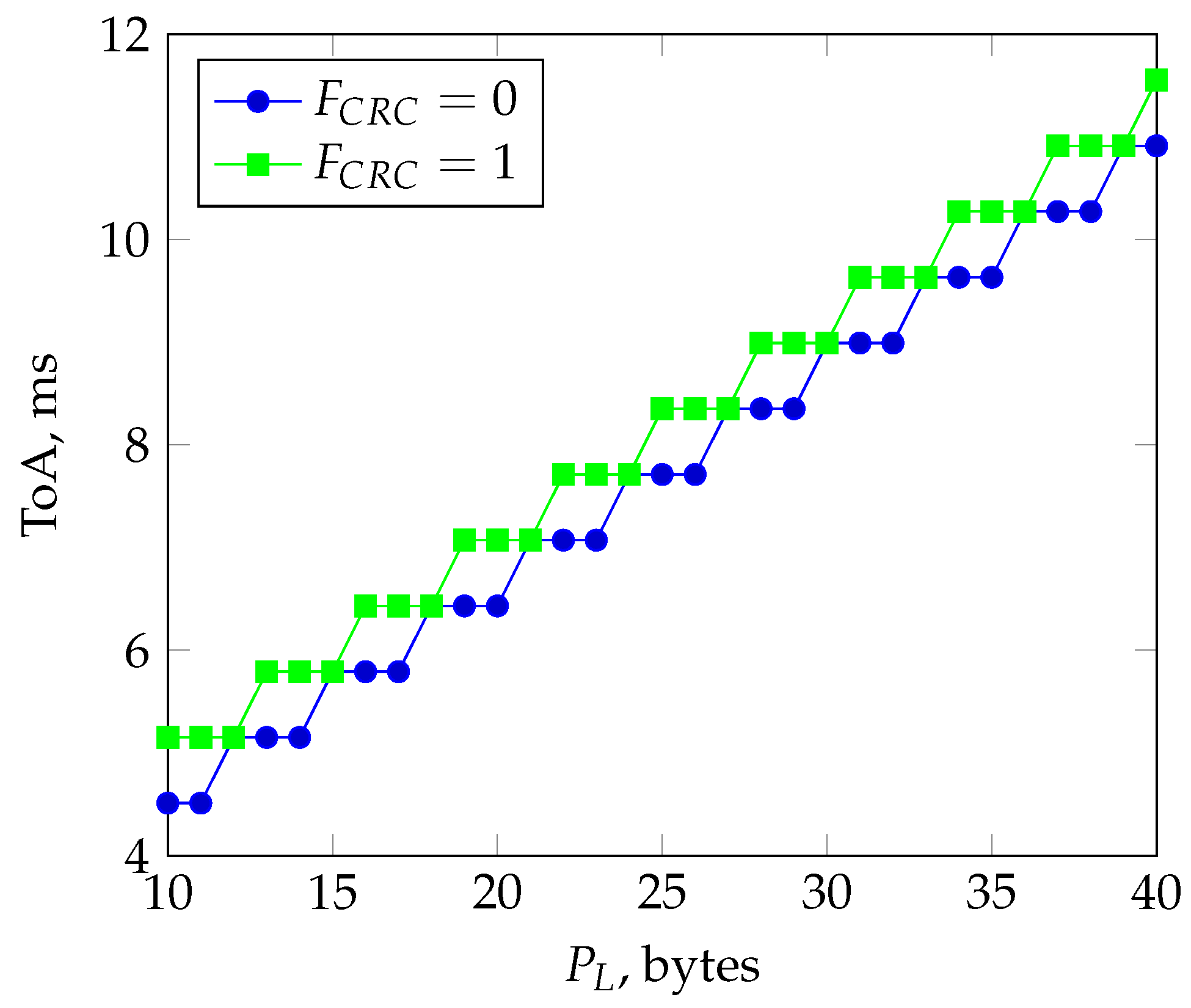
  • the number of LoRa packet payload bytes (1 to 255) P L ;
  • the Spreading Factor (6 to 12) S F ;
  • the Implicit Header flag F I H : F I H = 0 when the header is enabled, F I H = 1 when no header is present;
  • the Data-rate optimization Enabled flag D E : D E = 1 when so-called Low Data Rate Optimization is enabled, D E = 0 otherwise;
  • the Coding Rate C R : 1 corresponds to coding “4/5”, 4—to coding “4/8”;
  • the CRC flag F C R C : 1 corresponds to CRC enabled.
Most important result is that LoRa data transmission length does not depend linearly on the length of the data packet. So taking P L = 18 , S F = 6 , F I H = 1 , D E = 0 , C R = 1 , F C R C = 0 , B W = 500 kHz, n p r e a m b l e = 8 calculations give T o A equal to approximately 6.4 ms; dependence of ToA on P L = { 10 . . 40 } and F C R C = { 0 , 1 } in Figure 4 shows that T o A is constant for small variation of the P L . Use of P L = 18 bytes gives the same T o A = 6.4 ms for both F C R C = 0 and F C R C = 1 , allowing to experiment and determine the need to set the CRC flag.
Due to constant messaging during operation, such a cell broadcasting system brakes actual Industrial, Scientific, and Medical (ISM) band regulations [39,40], thereby a system should be used in a licensed band.

3. Pre-Implementation Performance Evaluation

3.1. Architectural Design Considerations

Any radio chip can be connected to an embedded system in two ways:
  • Directly to the host micro-controller unit (MCU) or processor system. In this case, if the host is busy processing real-time data of the vehicle, than there is a risk for implementation of the real-time radio chip management since radio chip demands real-time reaction from the host;
  • Via dedicated radio chip controller connected to the host system. In this case, the host can be busy and that does not degrade real-time radio chip operation since its primitive events (like setting the radio chip parameters, building packets for transmission, and parsing incoming ones) serves the dedicated radio-chip controller. As a result, the local (relatively to the RSU) dynamic network has better chances to stay organized and connected.
Since the latter variant reduces restrictions on to the vehicles host MCU real-time properties (usually reducing the implementation costs as well), it is preferable to implement a real-time radio network in the second way. But in this case, there are two variants of where to implement the network layer responsible for network cell management of the real-time TDMA cellular network:
  • On to the host MCU;
  • On to the dedicated radio chip controller.
The proper choice is very important since there are strict performance criteria that in the planned vehicular network have to be met [37], so an experiment was conducted in order to determine packet throughput in the case when the TDMA vehicular network is implemented on the host.

3.2. Setup and Methodology

One of the requirements of the solution being developed is to use off-the-shelf LoRa radio modules, leading to an empirical hardware-in-the-loop evaluation that integrates embedded systems testing, protocol benchmarking, and real-time communication testing.
The test stand was made by two systems, each containing the following:
The radio modules were programmed with a custom firmware called the LARio (LoRa Advanced Radio input/output) modem that, upon starting, ensures basic LoRa radio modem functionality. To facilitate application development with the LARio modem, a dedicated host-side API was developed. It runs in a separate thread and implements the Transport and Session layers of the OSI model [36]
During tests, each system was placed in a separate room imitating distant but not radio-shielded vehicle placement; radio communication parameters were as follows:
Output power:−3 dBm (ISM 868 MHz band in combination with low transmitted power was used for all indoor and outdoor tests);
Modulation:LoRa;
Spreading factor:SF6;
Header mode:implicit header;
Frequency:868.5 MHz;
Channel hoping:off;
Bandwidth:500 kHz;
Coding rate:4/5;
CRC:off;
IQ inversion:off;
Preamble length:12.25 (including 4.25 added by radio chip);
Payload:18 bytes;
Serial port baud rate:115,200 bps.
To determine the packet throughput of such a test stand, a program was written that made two host controllers send each other the MCBP messages as fast they can fixing communication results in log files on the computer connected to both controllers via Ethernet. Log files were reviewed and approximate time slot size was calculated.

3.3. Performance Analysis

During testing in stable communication conditions (no packet loss), 1691 incoming packets in a size of 18 bytes were received in 109678 ms, giving approximately 65 ms per one sent and one received packet or around 33 ms per a single packet. According to Semtech documentation, the LoRa chip is capable to transmit such a packet in approximately 6.4 ms. Such a bad host–radio–host performance during experiment for a described setup can be explained by the following:
  • Complex and slow data flow:
    • Packet is placed onto the host system;
    • Packet is transferred to the radio chip controller via not the fastest serial connection (transfer of 18 bytes takes near 1.6 ms!);
    • Radio chip is programmed according to the transmission’s settings, radio chip’s power amplifier is awakened;
    • Radio chip controller sends data to the radio chip via SPI (8 MHz clock);
    • Packet is transmitted;
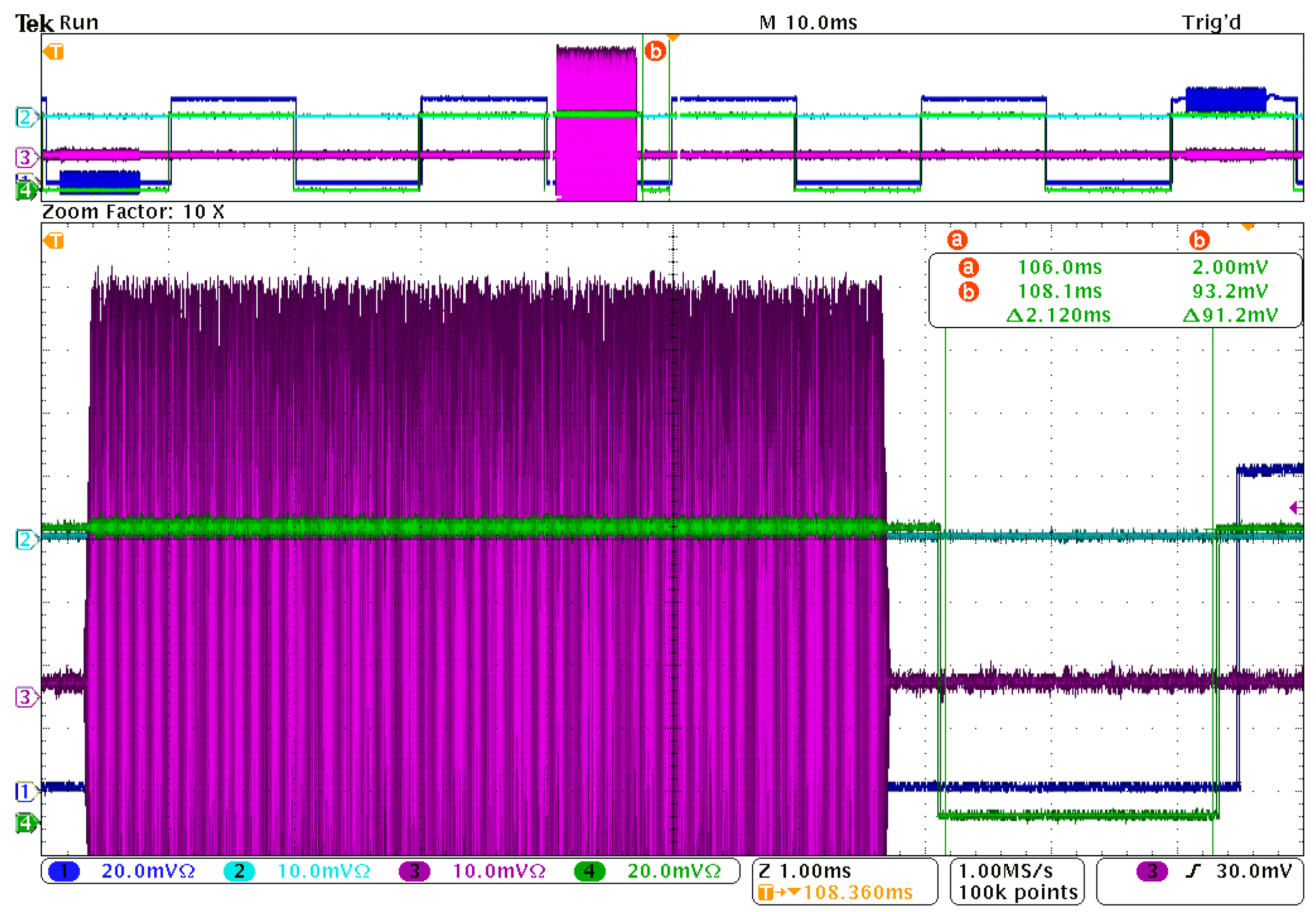
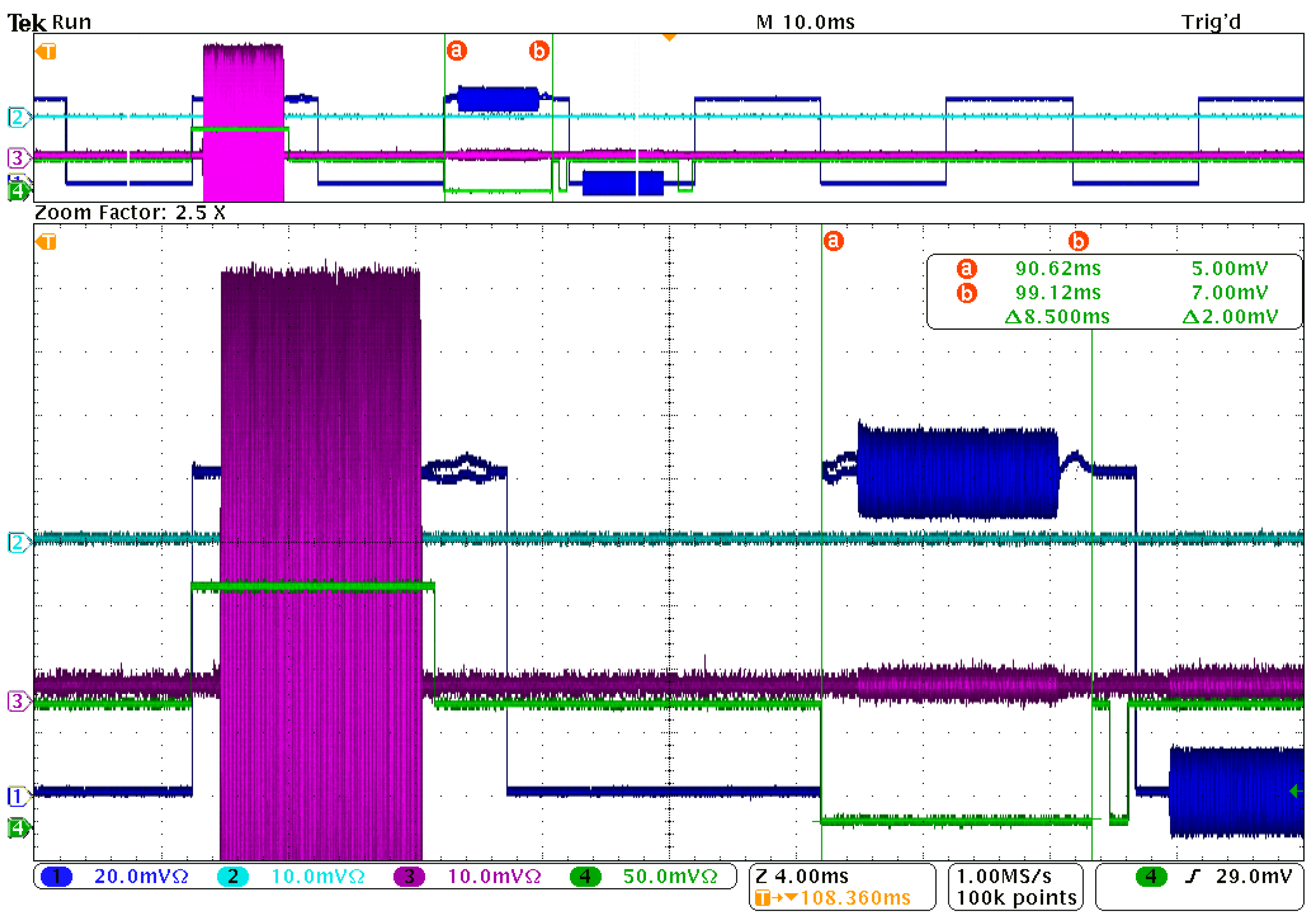
    • On the receiving side, the received packet is transferred from the radio chip to the radio chip controller via SPI; according to the measurements made with the help of an oscilloscope, this and three previous steps together take around 8.5 ms using the described radio settings);
    • Packet is transferred to the host (again 1.6 ms);
  • Non-real time behavior of the host system was observed during experiments when it was working with serial ports: incoming data became delayed for many ms that resulted in the most devastating impact on to the packet throughput. This behavior actually dictated the implementation of the mentioned LARio modem API service thread on the host that worked like proxy, masking delays in serial communication and simplifying the communication with the LARio modem from user application on the host providing ready-to-use functions for lightweight access to LARio modem functionality.
Measured performance resulted in the packet rate equal to 30 packets per second. TDMA, with a time-frame following frequency 3 Hz, can create 10 time slots in a time-frame. If one time slot is reserved for network management needs and the RSU occupies one time slot, then eight client CAR nodes can join such a network cell. Since cell client data refresh rate for practical vehicular network applications should be at least 10 Hz [9], the measured performance for the given time slot occupancy ensures connection only from a single car. Accordingly, this experiment demonstrates that the network cell integrity control cannot be delegated to the host system but must be carried out by the microcontroller of the radio module. This determines the following development path of MCBP.

4. Implementation and Results

4.1. Hardware

MCBP is implemented onto the off-the-shelf Microchip’s RN2483A module (http://ww1.microchip.com/downloads/en/devicedoc/50002346c.pdf (accessed on 23 March 2025). In order to be a part of the vehicular network and ensure the planned functionality, the module should be connected to the vehicular system’s host controller that should refresh vehicle data in module for network broadcast regularly via serial connection. Data to the module are sent via a serial connection in binary mode in order to minimize the impact of the limited serial port speed (115 kbps) on to the network broadcast performance.
To achieve stable communication, the RN2483A module-specific features were exploited: the built-in microcontroller was clocked at 64 MHz using clock frequency multiplication by means of its PLL, interrupts were rearranged, one of its counters was used as a software-independent time slot counter, and one counter was used for software independent time-frame restart.

4.2. LoRa Stack

LARio modem firmware was developed on top of the original Microchip’s RN2483A module sample code by elimination of the LoRaWAN functionality and building-up code for the LARio modem.
It has two main operation modes:
  • Fully functional binary data radio modem;
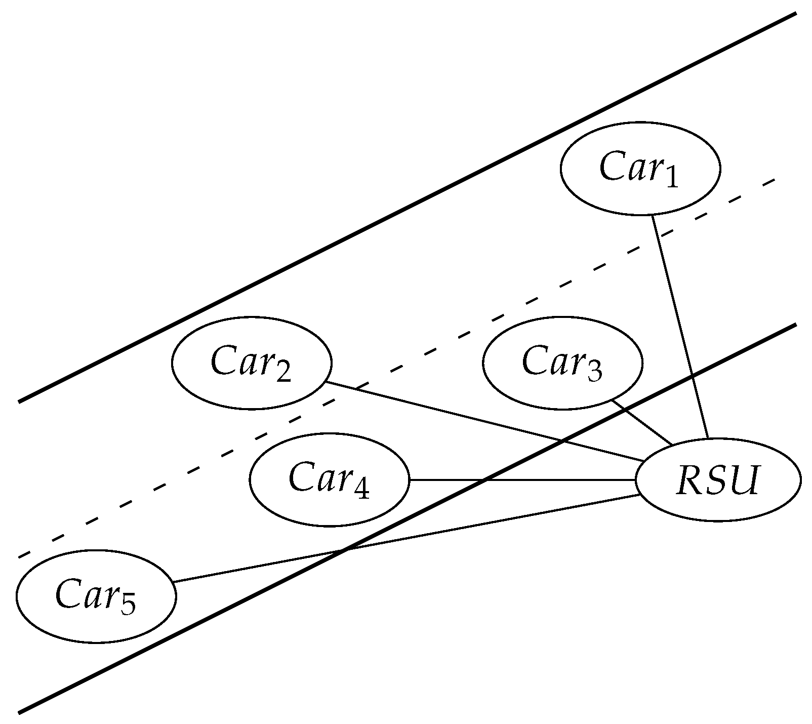
  • Organization of and participation in MCBP message broadcast cells (supported by RSU and CAR host computers) for up to seven network members: RSU and six CAR nodes (proven working in test, see below).
In the modem mode, it does not care about MCBP packets and does not try to interpret any incoming packets; it works as an usual radio modem that receives an transmits binary data packets according to the programmed radio settings that can be changed sending commands via a serial port. This mode allows implementation of any data transfer protocol from a host attached to the LARio modem using both LoRa and FSK modulation. However, a custom protocol developer has to configure the serial port data rate for non-standard speed large enough (up to 1 Mbps) in order to exploit the fastest FSK mode (up to 300 kbps).

4.3. MCBP Stack

MCBP stack has been developed for the application in ITS. The requirements to the vehicular network broadcasting and messaging capabilities are defined and described in Appendix C of [9]; it defines the following:
  • Resolution of car coordinates: accuracy of the car coordinates is defined as a number 1–5 in meters except cases C.1.4.1 “Overtaking vehicle warning” and C.1.5.4 “Intersection Collision Warning” when positioning accuracy is defined as “Accurate positioning of vehicles on digital map” and C.1.5.5 “Co-operative forward collision warning” when positioning accuracy must be less than 1 m;
  • Minimum period of messages: the most important message broadcast period is defined as 10 Hz;
  • Maximum latency of messages: for the most messages, it is defined as 100 ms except case C.1.4.3 “Pre-crash sensing warning” when latency is defined as 50 ms (for similar cases C.1.5.1 “Across traffic turn collision risk warning”, C.1.5.2 “Merging Traffic Turn Collision Risk Warning” etc. it is 100 ms);
  • Message content: each message application defines its content to fulfill the specific application case; in some cases, necessary information can be derived from car direction, speed, and current coordinates; in most cases, it is all the data needed;
  • Message usage cases and communication mode that both are related to the message class: for example, warning messages should be transmitted for only a limited time whilst informative messages should be transmitted permanently periodically or periodically triggered by an authoritative message from RSU.
For MCBP, a CAM message was radically shortened from 300 to 18 bytes accepting the fact that MCBP is taken into account only as an emergency connectivity service when base connectivity services are not available; the new message format includes all necessary data for safe critical vehicle operation: message type, unique car ID, vehicle type, received RSU signal level, heading, altitude, latitude, longitude, GPS Error, GPS timestamp, CRC.
MCBP can be described using specific terms to define different subjects of functioning specifics:
  • Hardware Zone Beacon Manager (HZBM) is usually on the RSU mounted embedded system with an attached LARio modem that, with the help of a specific command from the host, is configured to work as a network cell master. An according working mode of the LARio modem is called the “RSU mode”;
  • Software Zone Beacon Manager (SZBM) is usually a non-stationary dynamic self-organizing network master. An according working mode of the LARio modem has not been developed yet;
  • Car Traffic Data Manager (CTDM) is usually an on-vehicle mounted embedded system with an attached LARio modem that, with the help of a specific command, is configured to work as a network cell client. An according working mode of the LARio modem is called a “CAR mode”.
The chosen topology not only eases development but also ensures a higher level of security (https://resources.lora-alliance.org/security/lorawan-is-secure-but-implementation-matters (accessed on 2 May 2025). To ease protocol debugging, the current MCBP implementation does not use any packet encryption, so encryption key exchange or distribution is not handled yet. The frame starting time slot is sent by RSU and contains the cell organization data; the RSU broadcasts the second packet about itself in the next time slot.

4.3.1. MCBP Stack, RSU Mode

In RSU mode LARio modem acts as a MCBP stationary cell master that is supposed to reside on RSU. This mode sets up a timer that 10 times per second transmits MCBP synchronization packet containing MCBP cell organization data following with a packet containing data about RSU itself (information for CAR nodes). Each packet time slot is 12.5 ms long in the case of 8 time slots in time-frame (6 clients).
In this mode all incoming data packets are checked and parsed by LARio modem: if there is a valid MCBP client packet in expected time slot, modem updates internal tables of network consistency and refreshes data about connected clients. If a client does not report its presence via data packet, it is “forgotten” after 3 s to clear time slot for a new vehicle.

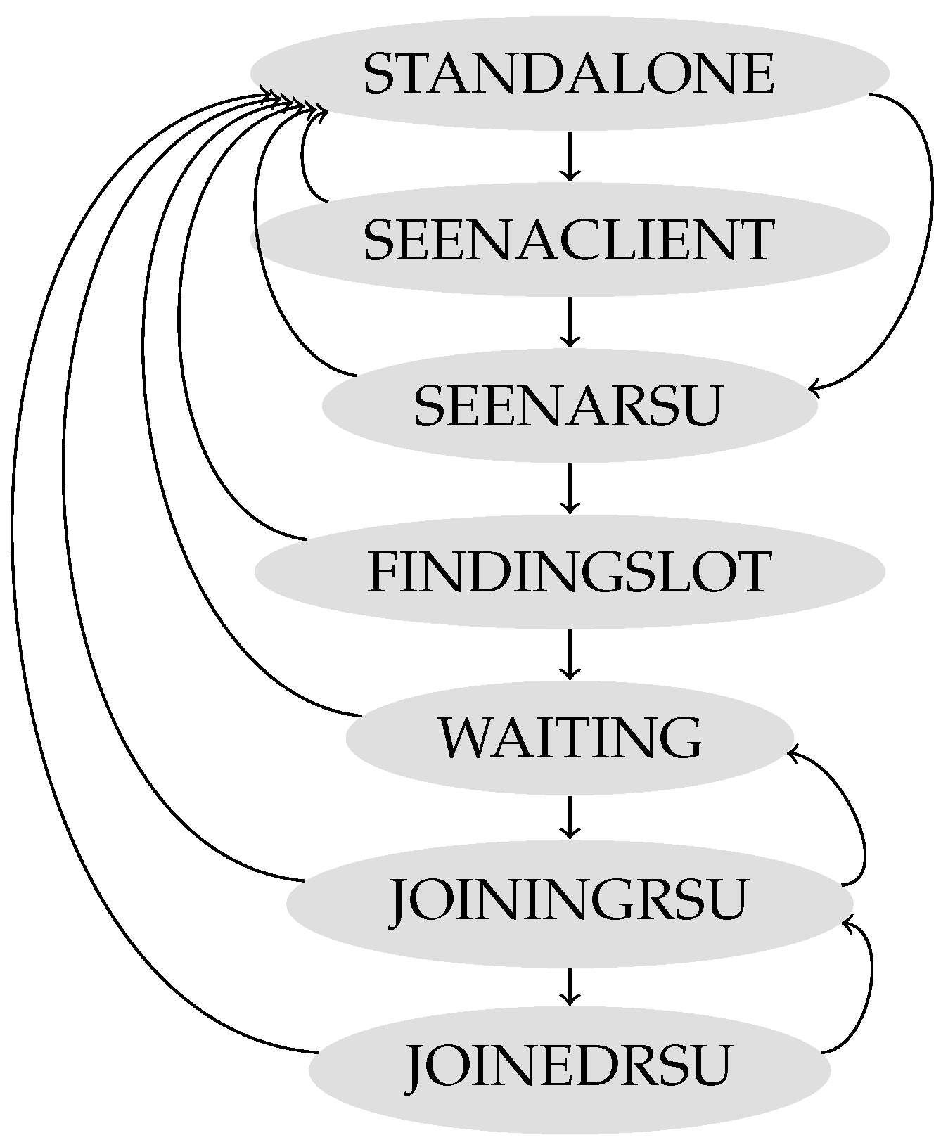
4.3.2. MCBP Stack, CAR Mode

In the CAR mode, the LARio modem acts as an MCBP cell client that is supposed to reside on the vehicle. This mode enables verification of compliance with the MCBP of all incoming packets, synchronizes internal timer and time slot counter to the start of the time-frame, updates internal data structures and state machine states according to the data in received MCBP packets, and enables a timer that transmits CAR data 10 times per second if the CAR node is accepted by the RSU node as a valid MCBP cell client. In this case, the second timer is set up to count the time slot in the hardware to avoid time slot jitter due to interrupted processing. Both timers are synchronized with the RSU timer by means of the network management packet from the RSU.
The state machine of the LARio modem working in the CAR mode is shown in Figure 5. At the start, the CAR node is in the STANDALONE state; then, the state linearly steps to JOINEDRSU if each state ends successfully; if not, the state in most cases jumps to STANDALONE. The short description of states and transitions is as follows:
  • STANDALONE: if a valid RSU packet is received, the state switches to the SEENARSU state; if a valid CAR packet is received, the state switches to the SEENACLIEN state. These states are utilized in later stages of MCBP development;
  • SEENACLIENT: this state in the CAR mode has the same meaning as the STANDALONE state; if a valid RSU packet is received, the state switches to the SEENARSU state. This state is used in the next development stages in a dynamic network cell of clients with equal rights to be elected as Software Zone Beacon Manager;
  • SEENARSU: this is an intermediate state used to minimize EMI noise impact on to the process of joining to the network cell. If a valid RSU packet is received again, the state switches to the FINDINGSLOT state to start joining the RSU managed cell;
  • FINDINGSLOT: in this and next states, if a valid HZBM packet is received, the node chooses or updates a random not taken network node identification number (NNID), a free time slot, and a random time-frame delay counter from one to three. In this state, the CAR node then enters the WAITING state if in cell at least one time slot is free.
    The random not taken NNID is used to allow the CAR node control the response from the RSU node and identify itself during the process of the CAR node joining to the RSU node-organized HZBM cell. Random time-frame delay counter is used to avoid collisions potentially made by multiple joining CAR nodes aiming to transmit in the same time slot.
    In this and next states, if other CAR node messages are received, the current CAR node updates internal data structures about their NNID and corresponding time slots;
  • WAITING: in this state, the CAR node after reception of the MCZB package re-plans the time slot number and compares it with the previously generated: if the time slots are the same, the random time-frame delay counter is decremented and the node enters the next state when this counter reaches zero. If the re-planned time slot is zero, the state is reset to STANDALONE since there are no free time slots anymore;
  • JOININGRSU: during this state, the CAR node is transmitting its data packet in a chosen time slot; if the CAR node can identify itself as a valid network node in the following MCBP network organization packet sent by the RSU node in time slot zero of the next time-frame, it changes the state to JOINEDRSU. Otherwise, it re-plans the time slot number again and compares the re-planned time slot number with the previous one: if teh time slot is the same and the random time-frame dalay counter is not zero, the state is changed back to WAITING; if the updated time slot is zero, the state is reset to STANDALONE; otherwise, the state is changed to WAITING;
  • JOINEDRSU: in this state, other CAR node data messages can be processed according to the meaning of data in the current MCBP cell. If the CAR node finds that in the HZBM network organizing the packet the actual time slot is assigned to the different CAR node, it concludes that the RSU node was not able to receive the current CAR node messages for more than Time To Live time (3 s) and gives an according time slot to the other CAR node. In this case, the current state is changed to JOININGRSU.
Figure 5. State machine of MCBP stack in the CAR mode.
Information 16 00447 g005

4.4. MCBP Stack: Test Setup

To test the developed protocol, a total of 10 LARio modems were connected to the PC using RS-232/USB converters in order to test different time-frames with time slot count varying from 8 to 10: one modem was always acting as a radio channel monitor working in a non-MCBP mode, one was acting as an RSU node, and other modems were used as CAR nodes. To ease debugging and tests, a special software was written using LabVIEW allowing to interpret, in real time, the real-time digital data from the monitor, RSU, and up to eight CAR nodes. To observe RF signals in real time and measure timing, all RF outputs of LoRa modules were connected to the 1 GHz Tektronix mixed-signal oscilloscope MSO 4104 by means of RF splitters and resistive power combiners. This setup was also used in order to observe different statuses of different nodes; statuses were linked to the output pins of the RN2483A module by output pin control commands of module MCU.

4.5. MCBP Stack: Test Results

The test showed that the developed protocol works properly, ensuring the following:
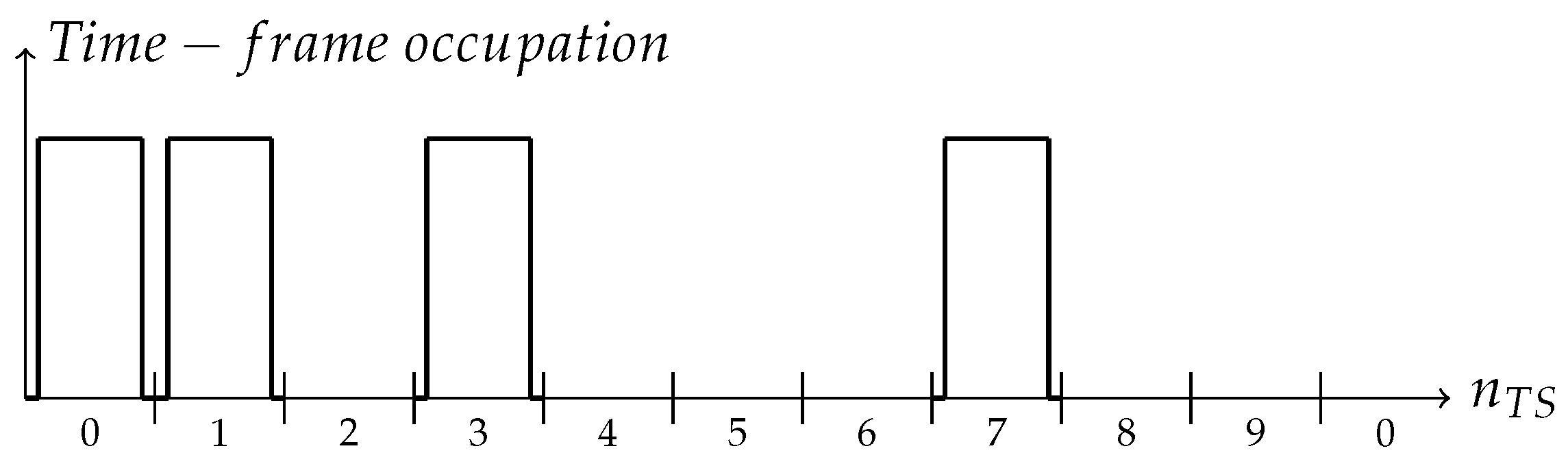
  • TDMA frame size 100 ms; accordingly, data latency can be no larger than 100 ms if the host connected to the node updates transmitted data with a frequency no lesser than 10 Hz;
  • Broadcast message size 18 bytes (14 bytes payload data);
  • Stable communication for time slot count equal to eight.
Figure 6 shows the oscilloscope snapshot for the fully allocated eigh-time-slot time-frame of the MCBP TDMA network cell: the first is an RSU cell organization packet, the second is an RSU data packet, the rest are packets from randomly allocated CAR nodes. The x-axis represents time (10 ms interval) while the y-axis shows the analog RF mixer signal. Variations in amplitude across LoRa modules are due to differences in placement. Signal overlap is visible, particularly from modules assigned to the fourth, fifth, and eighth time slots. The oscilloscope snapshot enables visual assessment of channel synchronization and helps identify whether any modules have dropped out.
The timing of different events in a time-frame was measured in order to determine the average value and variation of these events; most important measurements are illustrated in Figure 7 and Figure 8; most important measurement results are shown in Table 2. These measurements were made for time-frames with 10 time slots in order to determine the reason for communication instability working in such a TDMA mode. The oscilloscope screenshot in Figure 7 displays all time slots (top of the image) along with precise timing measurements using the built-in tool. The bottom section shows a 10× zoom of a selected area to highlight critical timing details. In the upper part, Time Slot 0 (the RSU’s frame-start packet) appears at the far right, while Time Slot 1 (another RSU packet) is on the left; both analog RF signals are represented in blue. The zoomed-in lower image focuses on Time Slot 5, where a module is active, to analyze timing accuracy and assess whether the PIC24 microcontroller meets the required phase jitter and timing precision for frame stability. The reason of cell instability in this case can be seen in Figure 8: the time gap between the moment when a CAR finishes the parsing of incoming HZBM packet and the start of the next time slot (RSU informative slot) is too narrow so the jitter of time slots in clients leads to the desynchronization of the channel access and disintegration of the cell.
Testing shows that future work can be focused on fine-tuning of the different delays introduced by the software in different operating modes of the node and reduction in the received information processing time in order to make stable communication time slot equal to 10 ms, thus increasing the network cell member count from seven to nine, while the code can be upgraded in order to support larger networks.

4.6. Applications

MCBP can be used for most of the application cases in [9]; all necessary information should be derived from message data by the host computer. Message usage cases and the communication mode should also be controlled by the host computer since the LARio modem that expects information for MCBP broadcasts to be regularly updated by the host.
The proposed solution has broad applications, beyond serving as a fallback emergency layer in ITS solutions. It can be used to organize and coordinate the control of autonomous agents (e.g., autonomous vehicles, mobile robots, drones) within a certain area, including search and rescue operations, warehouse logistics, construction sites, field deployment, field mapping, and platoons. The proposed system can operate independently of mobile networks and is applicable in environments with unreliable Internet connectivity. A fixed or mobile master node coordinates data exchange in real time, assigning time slots and maintaining synchronization, allowing autonomous agents to share information (e.g., location, sensor data, task status) using standard, inexpensive LoRa modules. The developed local radio cell can also be expanded into larger systems using inter-cell coordination or handover, paving the way for expanded coverage in future deployments.

5. Discussion

MCBP is planned to help improve the traffic of cars locally. At the current stage of development, the MCBP has single-hop star topology and organises in the cell to the RSU closest client nodes. MCBP currently does not support message routing between nodes or cells.
The current implementation of MCBP is planned to connect up to eight clients (ten time slots in a 100 ms time-frame) per network cell (not counting the cell master). It is tested in a configuration with eight time slots per a 100 ms time-frame ensuring stable connection for six clients. Fine tuning of the delays in code has to be perfomed in order to ensure stable working in a configuration with ten time slots per time-frame or more. A powerful computing module has to be used in order to reduce T I G G .
The real-time part of the vehicular network should be implemented using dedicated MCU for control of the LoRa radio chip; if node host MCU is capable to update information in the LARio modem not less frequently than 10 times per second, then MCBP ensures maximal latency of the node equal to 100 ms. This is 20 times less than estimated in [29] for LoRa technology, up to 62 times less than in [31], and 120 times less than in [25].
The use of smaller spreading factors for LoRa modulation allows the increase in cells node count and/or reduction in information latency in a cell.
MCBP uses a non-ISM compatible data exchange scheme in order to fulfil the requirement to exchange data between vehicular network cell nodes at least 10 times per second. Accordingly, the working frequencies should be shifted to a band that demands licensing. Nevertheless, the implementation allows to change the broadcast timing and limit the T o A of any node in order to satisfy ISM band limitations of the particular MCBP implementation that does not demand the full-time data streaming nature like CAM messaging.
At the current stage of development, it is already clear that LoRa module configuration with an output power of −3 dBm and modulation steepness SF6 and SF7 ensures mobile cell size that is too large (SF7 ensures cell radius up to 200 m [23,33,38]) for real car density since such a cell can fit a lot more cars than MCBP implementation-supported TDMA slots: many communicating cars make a strong interference (too strong even for LoRa) to each other and effectively disable MCBP functioning. The radius of the mobile cell can be reduced: (a) reducing the output power of the transmitter; (b) using faster LoRa modulation than SF6 or using FSK modulation with additional error correction overlay (e.g., with packet re-transmission like in [23]) to ensure that finally formed signal transmission channel has channel stability similar to that of the channel made using LoRa modulation but for shorter distances (up to 50 m).
Large cell size can be exploited in a different way. Smaller-sized cells in the message path effectively speed up message transfer from the message source to the message recipient for the limited amount of special cars (e.g., emergency services) after upgrading the existing implementation by adding message routing functionality.
For some really small vehicular systems it could be possible to implement vehicle data refresh and network data processing procedures in the RN2483A module itself. It has some General Purpose Input/Output pins available that can be connected to vehicle sensors and a 64 kB ROM that is allocated by around 50% implementing the LARio modem and thus making implementation of joint MCBP and the vehicular system not only cost- but also power-effective [23,41].

6. Conclusions

MCBP advances the state of the art not by inventing entirely new concepts from scratch, but by combining existing technologies (LoRa, TDMA), and through engineering (firmware development, on-module network control) creates a practically implemented, tested, stable, and high-performing protocol for a crucial niche in vehicular communications, i.e., reliable and affordable emergency broadcast layer. The detailed results on latency, jitter, and dynamic stability provide tangible evidence of its benefit.
Although MCBP is developed for the application in intelligent transportation systems, it can be easily adapted for swarm organization needs or stationary embedded system cell network broadcast messaging.
Future tests will be performed in order to determine reliability of the current CAM messaging implementation versus implementations using Wi-Fi and GPRS.
Future work can also include implementation of dynamic node clustering ensuring dynamic cell master (SZBM) election, improved security ensured by packet encryption, compliance with the ISM frequency regulations, dynamic node management, network cell clustering, and message routing.

Author Contributions

Conceptualization, M.G. and A.L.; Data curation, G.G.; Formal analysis, M.G., G.G. and A.L.; Funding acquisition, M.G.; Investigation, G.G. and A.L.; Methodology, M.G., G.G. and A.L.; Project administration, M.G.; Resources, M.G., G.G. and A.L.; Software, G.G.; Supervision, M.G.; Validation, G.G.; Visualization, G.G.; Writing—original draft, M.G. and G.G. All authors have read and agreed to the published version of the manuscript.

Funding

This research was partialy funded by Horizon2020 project “AutoDrive” grant number 737469.

Institutional Review Board Statement

Not applicable.

Informed Consent Statement

Not applicable.

Data Availability Statement

Data are contained within the article.

Conflicts of Interest

The authors declare no conflicts of interest.

Abbreviations

The following abbreviations are used in this manuscript:
CAMCooperative Awareness Message
CTDMCar Traffic Data Manager
GPRSGeneral Packet Radio Service
HZBMHardware Zone Beacon Manager
ISMIndustrial, Scientific, and Medical
ITSIntelligent Traffic System
LARioLoRa Advanced Radio Input/Output
LTELong-Term Evolution [standard]
LoRaLong Range [radio, modulation scheme]
LoRaWANLoRa-Based Low-Power Wide-Area Networking Protocol
MCBPMobile Cell Broadcast Protocol
MCUMicro-Controller Unit
NNIDNetwork Node Identification Number
OSIOpen Systems Interconnection
P2PPeer-to-Peer
RSURoad Side Units
SFSpreading Factor (in form SF6: Spreading Factor 6)
SPISerial Peripheral Interface
SZBMSoftware Zone Beacon Manager
TDMATime Division Multiple Access
TMSTraffic Management System
ToATime on Air
V2IVehicle to Infrastructure
V2VVehicle to Vehicle
V2XVehicle to Everything
WiFiWireless Network Protocol

References

  1. Zhang, S.; Chen, J.; Lyu, F.; Cheng, N.; Shi, W.; Shen, X. Vehicular Communication Networks in the Automated Driving Era. IEEE Commun. Mag. 2018, 56, 26–32. [Google Scholar] [CrossRef]
  2. Guanetti, J.; Kim, Y.; Borrelli, F. Control of connected and automated vehicles: State of the art and future challenges. Annu. Rev. Control 2018, 45, 18–40. [Google Scholar] [CrossRef]
  3. Liu, W.; Hua, M.; Deng, Z.; Meng, Z.; Huang, Y.; Hu, C.; Song, S.; Gao, L.; Liu, C.; Shuai, B.; et al. A Systematic Survey of Control Techniques and Applications in Connected and Automated Vehicles. IEEE Internet Things J. 2023, 10, 21892–21916. [Google Scholar] [CrossRef]
  4. Adnan Yusuf, S.; Khan, A.; Souissi, R. Vehicle-to-everything (V2X) in the autonomous vehicles domain—A technical review of communication, sensor, and AI technologies for road user safety. Transp. Res. Interdiscip. Perspect. 2024, 23, 100980. [Google Scholar] [CrossRef]
  5. Wang, Y.; Szeto, W.; Han, K.; Friesz, T.L. Dynamic traffic assignment: A review of the methodological advances for environmentally sustainable road transportation applications. Transp. Res. Part B: Methodol. 2018, 111, 370–394. [Google Scholar] [CrossRef]
  6. Bharadwaj, R.; Deepak, J.; Baranitharan, M.; Vaidehi, V. Efficient dynamic traffic control system using wireless sensor networks. In Proceedings of the 2013 International Conference on Recent Trends in Information Technology (ICRTIT), Chennai, India, 25–27 July 2013; IEEE: Piscataway, NJ, USA, 2013; pp. 668–673. [Google Scholar]
  7. Zhou, Y.; Wang, J.; Yang, H. Resilience of Transportation Systems: Concepts and Comprehensive Review. IEEE Trans. Intell. Transp. Syst. 2019, 20, 4262–4276. [Google Scholar] [CrossRef]
  8. Alonso Raposo, M.; Grosso, M.; Després, J.; Fernández Macías, E.; Galassi, C.; Krasenbrink, A.; Krause, J.; Levati, L.; Mourtzouchou, A.; Saveyn, B.; et al. An Analysis of Possible Socio-Economic Effects of a Cooperative, Connected and Automated Mobility (CCAM) in Europe; European Union: Brussels, Belgium, 2018. [Google Scholar]
  9. ETSI. ETSI TR 102 638. Technical Report, v1.1.1, Intelligent Transport Systems (ITS); Vehicular Communications; Basic Set of Applications; Definitions; ETSI: Sophia Antipolis, France, 2009. [Google Scholar]
  10. Barrachina, J.; Garrido, P.; Fogue, M.; Martinez, F.J.; Cano, J.C.; Calafate, C.T.; Manzoni, P. Road side unit deployment: A density-based approach. IEEE Intell. Transp. Syst. Mag. 2013, 5, 30–39. [Google Scholar] [CrossRef]
  11. Lochert, C.; Scheuermann, B.; Wewetzer, C.; Luebke, A.; Mauve, M. Data aggregation and roadside unit placement for a VANET Traffic Information System. In Proceedings of the fifth ACM International Workshop on VehiculAr Inter-NETworking, San Francisco, CA, USA, 15 September 2008; pp. 58–65. [Google Scholar]
  12. Abdrabou, A.; Zhuang, W. Probabilistic delay control and road side unit placement for vehicular ad hoc networks with disrupted connectivity. IEEE J. Sel. Areas Commun. 2010, 29, 129–139. [Google Scholar] [CrossRef]
  13. Agafonovs, N.; Strazdins, G.; Greitans, M. Accessible, customizable, high-performance ieee 802.11 p vehicular communication solution. In Proceedings of the 2012 the 11th Annual Mediterranean Ad Hoc Networking Workshop (Med-Hoc-Net), Ayia Napa, Cyprus, 19–22 June 2012; IEEE: Piscataway, NJ, USA, 2012; pp. 127–132. [Google Scholar]
  14. Desai, M.; Manjunath, D. On the connectivity in finite ad hoc networks. IEEE Commun. Lett. 2002, 6, 437–439. [Google Scholar] [CrossRef]
  15. Foh, C.H.; Liu, G.; Lee, B.S.; Seet, B.C.; Wong, K.J.; Fu, C.P. Network connectivity of one-dimensional MANETs with random waypoint movement. IEEE Commun. Lett. 2005, 9, 31–33. [Google Scholar]
  16. Gore, A.D. Comments on “On the connectivity in finite ad hoc networks”. IEEE Commun. Lett. 2006, 10, 88–90, Erratum in IEEE Commun. Lett. 2006, 10, 359. [Google Scholar] [CrossRef]
  17. Ghasemi, A.; Nader-Esfahani, S. Exact probability of connectivity one-dimensional ad hoc wireless networks. IEEE Commun. Lett. 2006, 10, 251–253. [Google Scholar] [CrossRef]
  18. Li, Y.; Liao, J.; Li, T.; Zhu, X.; Zhang, L.; Xie, S. Several statistical parameters for one-dimensional Vehicular Ad Hoc Networks. In Proceedings of the 2010 2nd IEEE International Conference on Network Infrastructure and Digital Content, Beijing, China, 24–26 September 2010; IEEE: Piscataway, NJ, USA, 2010; pp. 709–712. [Google Scholar]
  19. Deshpande, P.; Hou, X.; Das, S.R. Performance comparison of 3G and metro-scale WiFi for vehicular network access. In Proceedings of the 10th ACM SIGCOMM Conference on Internet Measurement, Melbourne, Australia, 1–30 November 2010; pp. 301–307. [Google Scholar]
  20. Balasubramanian, A.; Mahajan, R.; Venkataramani, A. Augmenting mobile 3G using WiFi. In Proceedings of the 8th International Conference on Mobile Systems, Applications, and Services, San Francisco, CA, USA, 15–18 June 2010; pp. 209–222. [Google Scholar]
  21. Lehr, W.; McKnight, L.W. Wireless internet access: 3G vs. WiFi? Telecommun. Policy 2003, 27, 351–370. [Google Scholar] [CrossRef]
  22. Mikhaylov, K.; Petäjäjärvi, J.; Janhunen, J. On LoRaWAN scalability: Empirical evaluation of susceptibility to inter-network interference. In Proceedings of the 2017 European Conference on Networks and Communications (EuCNC), Oulu, Finland, 12–15 June 2017; IEEE: Piscataway, NJ, USA, 2017; pp. 1–6. [Google Scholar]
  23. Cattani, M.; Boano, C.A.; Römer, K. An experimental evaluation of the reliability of lora long-range low-power wireless communication. J. Sens. Actuator Netw. 2017, 6, 7. [Google Scholar] [CrossRef]
  24. Reynders, B.; Wang, Q.; Tuset-Peiro, P.; Vilajosana, X.; Pollin, S. Improving reliability and scalability of lorawans through lightweight scheduling. IEEE Internet Things J. 2018, 5, 1830–1842. [Google Scholar] [CrossRef]
  25. Cheung, Y.; Qiu, M.; Liu, M. Autonomous vehicle communication in v2x network with lora protocol. In Smart Computing and Communication, Proceedings of the 4th International Conference, SmartCom 2019, Birmingham, UK, 11–13 October 2019; Proceedings 4; Springer: Berlin/Heidelberg, Germany, 2019; pp. 398–410. [Google Scholar]
  26. Sanchez-Iborra, R.; Gómez, J.S.; Santa, J.; Fernández, P.J.; Skarmeta, A.F. Integrating LP-WAN communications within the vehicular ecosystem. J. Internet Serv. Inf. Secur. 2017, 7, 45–56. [Google Scholar]
  27. Salazar-Cabrera, R.; De La Cruz, Á.P.; Molina, J.M.M. Fleet management and control system from intelligent transportation systems perspective. In Proceedings of the 2019 2nd Latin American Conference on Intelligent Transportation Systems (ITS LATAM), Bogota, Colombia, 19–20 March 2019; IEEE: Piscataway, NJ, USA, 2019; pp. 1–7. [Google Scholar]
  28. Salazar-Cabrera, R.; Pachón de la Cruz, Á.; Madrid Molina, J.M. Proof of concept of an iot-based public vehicle tracking system, using lora (long range) and intelligent transportation system (its) services. J. Comput. Netw. Commun. 2019, 2019, 1–10. [Google Scholar] [CrossRef]
  29. Li, Y.; Yang, L.; Han, S.; Wang, X.; Wang, F.Y. When LPWAN meets ITS: Evaluation of low power wide area networks for V2X communications. In Proceedings of the 2018 21st International Conference on Intelligent Transportation Systems (ITSC), Maui, HI, USA, 4–7 November 2018; IEEE: Piscataway, NJ, USA, 2018; pp. 473–478. [Google Scholar]
  30. Li, Y.; Han, S.; Yang, L.; Wang, F.Y.; Zhang, H. LoRa on the move: Performance evaluation of LoRa in V2X communications. In Proceedings of the 2018 IEEE Intelligent Vehicles Symposium (IV), Changshu, China, 26–30 June 2018; IEEE: Piscataway, NJ, USA, 2018; pp. 1107–1111. [Google Scholar]
  31. Haque, K.F.; Abdelgawad, A.; Yanambaka, V.P.; Yelamarthi, K. Lora architecture for v2x communication: An experimental evaluation with vehicles on the move. Sensors 2020, 20, 6876. [Google Scholar] [CrossRef]
  32. CAMP Vehicle Safety Communications Consortium. Vehicle Safety Communications Project: Task 3 Final Report: Identify Intelligent Vehicle Safety Applications Enabled by DSRC; National Highway Traffic Safety Administration, US Department of Transportation: Washington, DC, USA, 2005. [Google Scholar]
  33. Adelantado, F.; Vilajosana, X.; Tuset-Peiro, P.; Martinez, B.; Melia-Segui, J.; Watteyne, T. Understanding the limits of LoRaWAN. IEEE Commun. Mag. 2017, 55, 34–40. [Google Scholar] [CrossRef]
  34. Piyare, R.; Murphy, A.L.; Magno, M.; Benini, L. On-demand TDMA for energy efficient data collection with LoRa and wake-up receiver. In Proceedings of the 2018 14th International Conference on Wireless and Mobile Computing, Networking and Communications (WiMob), Limassol, Cyprus, 15–17 October 2018; IEEE: Piscataway, NJ, USA, 2018; pp. 1–4. [Google Scholar]
  35. Samaras, K.; O’Brien, D.; Edwards, D. Analytical calculation of throughput of ALOHA based protocols in optical wireless data networks. IEE Proc.-Optoelectron. 2000, 147, 322–328. [Google Scholar] [CrossRef]
  36. Zimmermann, H. OSI reference model-the ISO model of architecture for open systems interconnection. IEEE Trans. Commun. 1980, 28, 425–432. [Google Scholar] [CrossRef]
  37. 5GAA. C-V2X Use Cases: Methodology, Examples and Service Level Requirements; GA Association: Sheffield, UK, 2019. [Google Scholar]
  38. Qin, Z.; Liu, Y.; Li, G.Y.; McCann, J.A. Performance Analysis of Clustered LoRa Networks. arXiv 2019, arXiv:1905.13510. [Google Scholar] [CrossRef]
  39. Electronic Communications Committee. ERC Recommendation 70-03; Electronic Communications Committee: Copenhagen, Denmark, 2018. [Google Scholar]
  40. Federal Communications Commission. FCC Part 15–Radio Frequency Devices, Code of Federal Regulation 47 CFR Ch. 1; 10-1-15 Edition; Federal Communications Commission: Washington, DC, USA, 2015. [Google Scholar]
  41. Khutsoane, O.; Isong, B.; Abu-Mahfouz, A.M. IoT devices and applications based on LoRa/LoRaWAN. In Proceedings of the IECON 2017-43rd Annual Conference of the IEEE Industrial Electronics Society, Beijing, China, 29 October–1 November 2017; IEEE: Piscataway, NJ, USA, 2017; pp. 6107–6112. [Google Scholar]
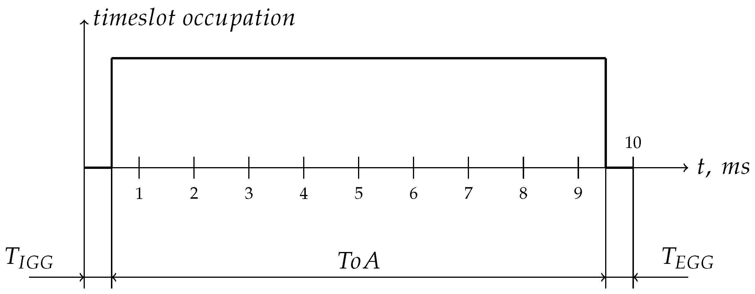
Figure 1. Organization of vehicles by RSU in a mobile broadcast cell: R S U —Road Side Unit, C a r X —vehicles. Natural radio propagation between cars is not shown.
Information 16 00447 g001
Figure 2. Transmission positioning in time slot: T I G G —transmission’s initial guarding gap, T o A —Time on Air, T E G G —transmission’s ending guarding gap.
Information 16 00447 g002
Figure 3. Time-frame occupation by active clients: n T S —time slot number in time-frame; occupied slots: 0, 1, 3, 7; the number of time slots in the time-frame N T S = 10 .
Information 16 00447 g003
Figure 4. ToA in dependency of P L and F C R C for S F = 6 , F I H = 1 , D E = 0 , C R = 1 , B W = 500 kHz, n p r e a m b l e = 8 (additional 4.25 added by radio chip).
Information 16 00447 g004
Figure 6. Fully allocated MCBP network eight time slot cell: dark blue—RSU sent network and RSU informative packets, azure—informative packets from first 4 cars, green—informative packet from 5th car, violet—informative packet from 6th car; green channel is catching leakage signals from nearby nodes.
Information 16 00447 g006
Figure 7. TDMA 10-time-slot time-frame event measurements: the minimum time of the RSU node from the reception of the packet sent at the 4th CAR node to the beginning of the next time slot: dark blue—inverted least significant bit of RSU time slot counter added with RSU radio, green—status of RSU incoming packet parser (high—inactive, low—processing incoming packet, valid for 4th CAR time slot), violet—informative packet from 4th car; azure—not used.
Information 16 00447 g007
Figure 8. TDMA 10-time-slot time-frame event measurements: the maximum time from the beginning of the time slot zero on RSU until the CAR node receives and starts processing the HZBM packet data. Graphs: dark blue—inverted least significant bit of RSU time slot counter added with RSU radio, green—statuses of 7th car at time slot eight (informative packet transmission: high—the packet preparation and transmission, 0—inactive, valid for 7th CAR time slot) and zero (receiving the HZBM packet: low—waiting for HZBM packet, 0—processing HZBM packet, low—inactive), violet—informative packet from 7th car, azure—not used.
Information 16 00447 g008
Table 1. Allowed ToA (plus transmission’s guarding gaps) for different numbers of cars N in a network cell.
N78910100
ToA, ms14.312.511.1101
Table 2. Measured MCBP time-frame timing.
N#EventAverage, msVariation, ms
1Time-frame size1000.05
2Time slot size12.50.05
3Time slot count8-
4RSU nodes time slot zero data packet delay after the time slot start1.380.05
5CAR node time slot zero jitter+0.1–−0.25-
6Minimal time after the RSU packet reception by CAR node till start of the next time slot1.90.05
7Minimal time after the packet transmission by CAR node till start of the next time slot20.05
8Delay after packet transmission till confirmation from RF chip0.40.05
9Time between time slot zero start and reception of the RSUs time slot zero packet by CAR node8.50.05
10Time between time slot zero start and moment when CAR node finishes processing of the RSUs time slot zero packet8.90.05
Disclaimer/Publisher’s Note: The statements, opinions and data contained in all publications are solely those of the individual author(s) and contributor(s) and not of MDPI and/or the editor(s). MDPI and/or the editor(s) disclaim responsibility for any injury to people or property resulting from any ideas, methods, instructions or products referred to in the content.

