Article

A Modified Selected Mapping Scheme for Peak-to-Average Power Ratio Reduction in Polar-Coded Orthogonal Frequency-Division Multiplexing Systems

by
Chao Xing
1,*,
Nixi Chen Hu
2 and
Ana García Armada
2
1
College of Information Science and Technology, Henan University of Technology, Zhengzhou 450000, China
2
Department of Signal Theory and Communications, University Carlos III de Madrid, E-28911 Leganes, Spain
*
Author to whom correspondence should be addressed.
Information 2025, 16(5), 384; https://doi.org/10.3390/info16050384
Submission received: 4 February 2025 / Revised: 27 March 2025 / Accepted: 31 March 2025 / Published: 6 May 2025
(This article belongs to the Section Information and Communications Technology)

Abstract

:
This paper proposes a modified polar coding-based selected mapping (PC-SLM) scheme to reduce the peak-to-average power ratio (PAPR) in orthogonal frequency-division multiplexing (OFDM) systems. In the proposed transmitter, modulated signal vector for a subset of frozen bits, termed PAPR bits, are precomputed, enabling a single polar encoder and modulator to generate multiple modulation symbols, thereby significantly reducing the hardware complexity compared to existing PC-SLM schemes. To achieve side information (SI)-free transmission, a novel belief propagation (BP)-based receiver is introduced, incorporating a G-matrix-based early termination criterion and a frozen bit check (BP-GF) for joint detection and decoding. Simulation results show that the proposed scheme significantly reduces PAPR across various code lengths, with greater gains as the number of PAPR bits increases. Furthermore, for PC-SLM schemes employing the partially frozen bit method, the BP-GF-based receiver achieves a PAPR reduction and error correction performance comparable to that of the successive cancellation (SC)-based receiver. Additionally, the BP-GF-based receiver exhibits lower decoding latency than the successive cancellation list (SCL)-based receiver.

1. Introduction

Orthogonal frequency division multiplexing (OFDM) is a multicarrier modulation scheme that is adopted in 5G. Because of its high peak-to-average power ratio (PAPR), it causes nonlinear distortion when it passes through power amplifiers. The selected mapping (SLM) scheme can effectively reduce PAPR by generating multiple OFDM signals and selecting the one with the minimum PAPR to transmit.
Arikan in 2009 [1] proposed polar codes that are proven to achieve channel capacity for any discrete memoryless symmetric binary input channels (B-DMCs) with low encoding and decoding complexity. Further, they have been selected as the standard coding scheme in the 5G enhanced mobile broadband (eMBB) control channel. The works [2,3,4,5] use polar codes to provide both error correction and PAPR reduction in the SLM scheme. In detail, ref. [2] uses a small number of frozen bits, so the extended information set will be sorted according to the PAPR metric. Then, the indices corresponding to the higher metric are selected to reduce the PAPR. Compared to [2], which employs the partially frozen bit method, refs. [3,4] utilize all frozen bits to reduce PAPR. Ref. [5] addresses the high PAPR issue in OFDM with index modulation systems by using multiple sets of frozen bits along with spatial modulation.
Some kind of side information (SI) is needed for the traditional SLM receiver, as it does not know which OFDM signal was transmitted. However, the receiver in [2,3,4] can work without SI using the structure of polar codes and polar decoding. In [2], all bits of the extended information set needs to be decoded, including the frozen indices that are used for the SLM method. In [3,4], the characteristics of the polar codes are used to detect which candidate signal was transmitted based on computing the path metrics of the successive cancellation list (SCL) decoding. However, due to the serial decoding nature of SCL, this approach suffers from high complexity and high latency.
To reduce the high latency caused by the SCL algorithm and consider the need for soft output, it is essential to explore the application of the belief propagation (BP) iterative algorithm in the SLM scheme. In this paper, we propose a modified SLM scheme for PAPR reduction based on polar coding without SI transmission. Q = 2 l OFDM signal candidates are produced by using a limited number l of frozen bits, called PAPR bits.
By offline calculating the modulation symbols (phase sequences) corresponding to PAPR bits, multiple phase-rotated modulation symbols can be obtained using only one polar encoder and one modulator. This approach eliminates the need for Q 1 polar encoders and Q 1 binary phase shift keying (BPSK) modulators. As a result, the proposed transmitter achieves a lower complexity compared to existing transmitters used in polar coding-based SLM (PC-SLM) schemes. To avoid SI transmission, we propose a modified BP algorithm with G-matrix-based early termination criteria and a frozen bit check (BP-GF) at the receiver. The main contribution of this work is as follows.
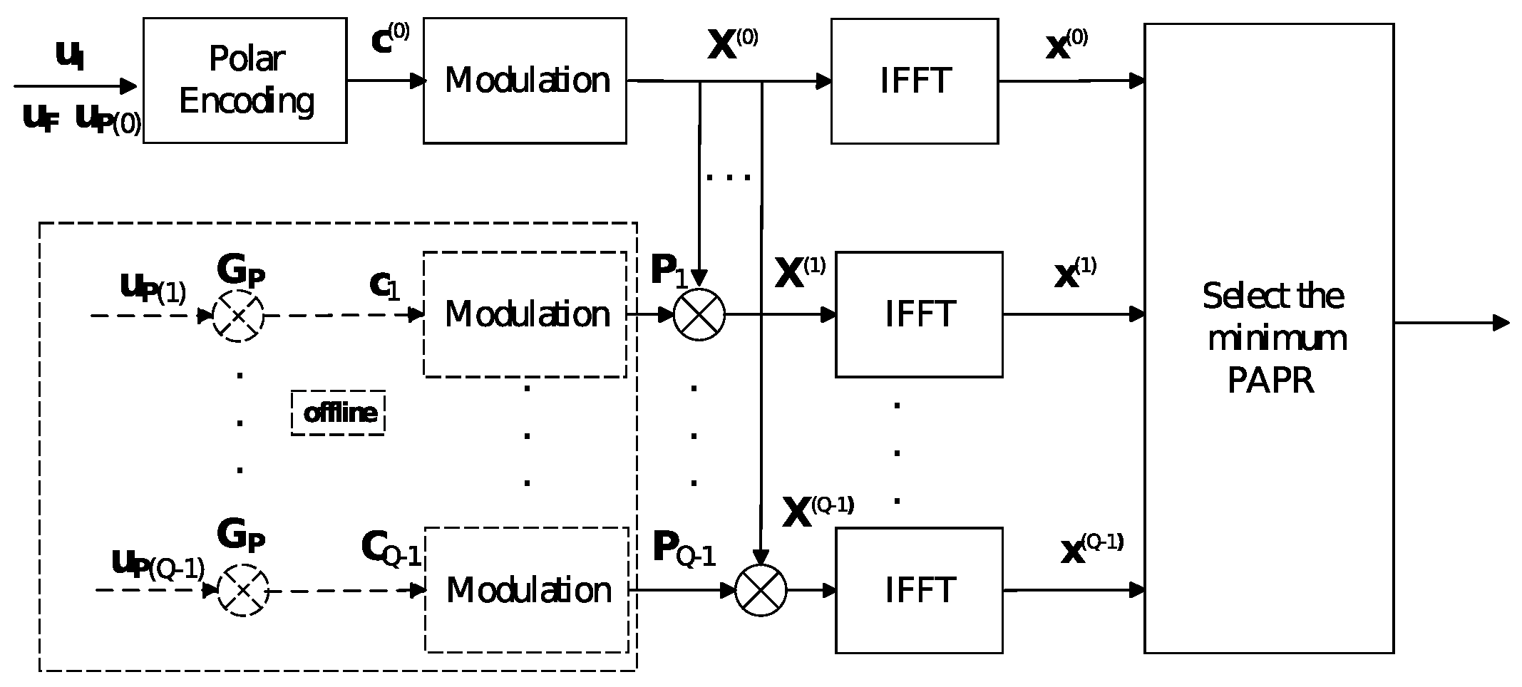
  • Since the PAPR bits are a small subset of the frozen bits and the modulated signal vector corresponding to the PAPR bits can be precomputed offline, Q 1 polar encoders and Q 1 BPSK modulators are eliminated at the transmitter. We achieve a lower-complexity SLM transmitter compared to existing PC-SLM schemes without any code rate loss.
  • At the receiver, the BP algorithm is applied to the SLM scheme, for the first time according to the authors’ knowledge. Our proposed SLM receiver utilizes a modified BP algorithm enhanced with detection capabilities to adapt to the SLM transmitter, eliminating the need for SI transmission.
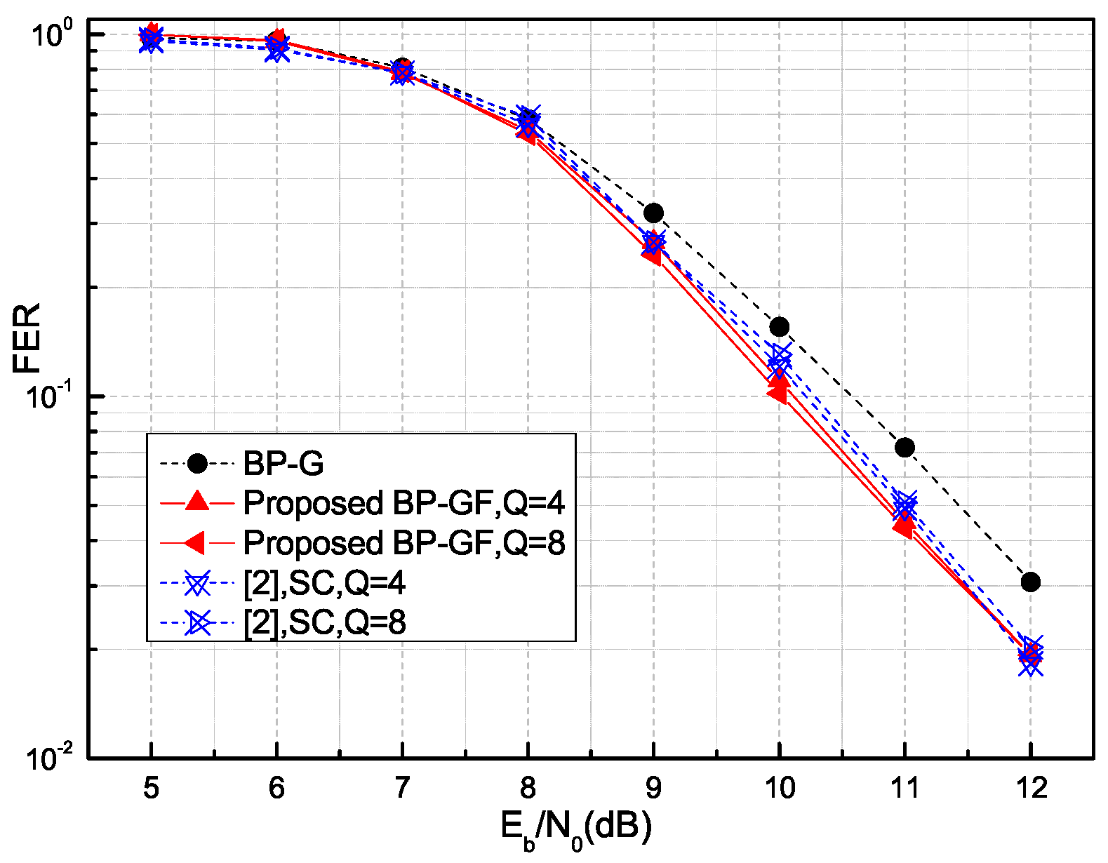
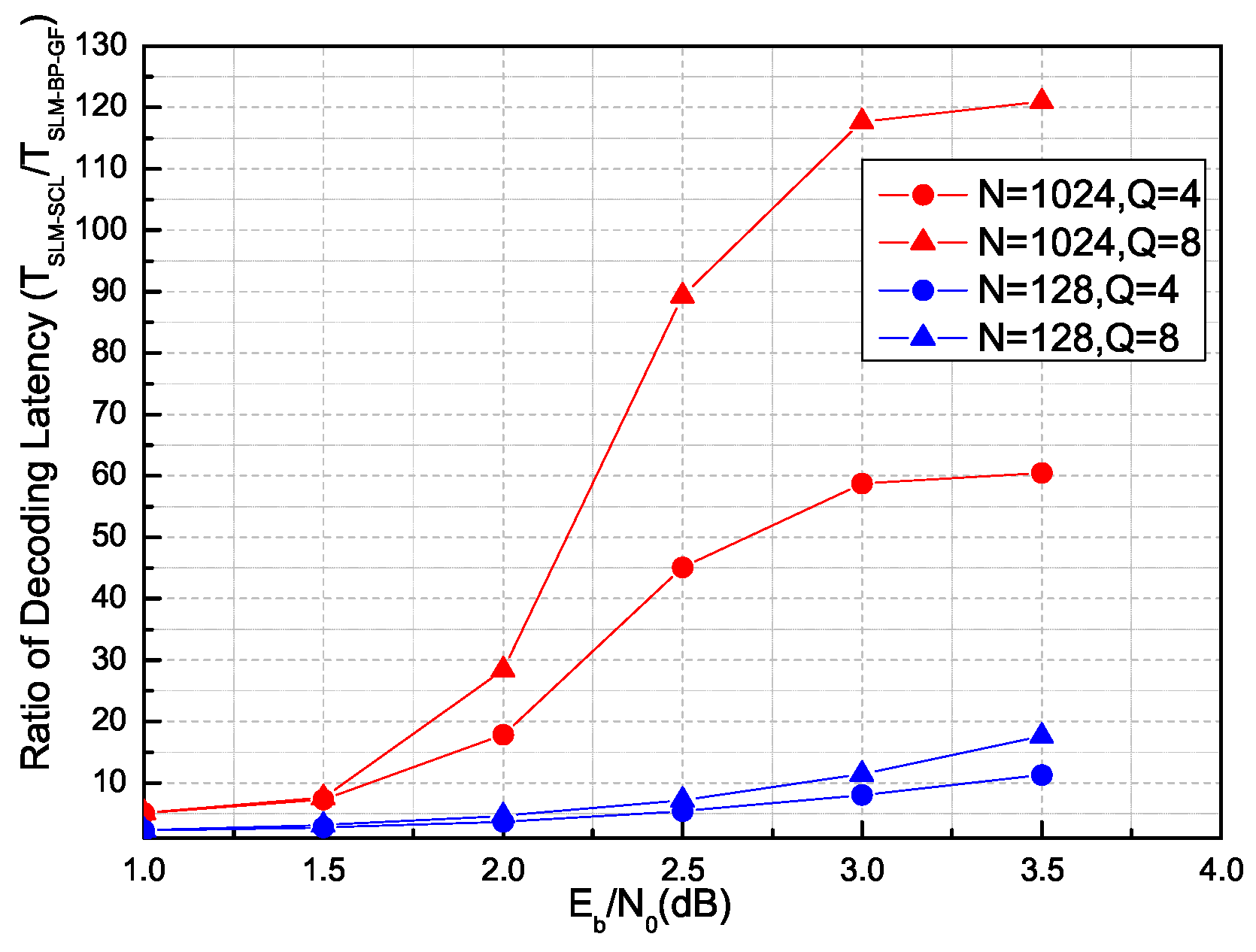
  • For the PC-SLM approach based on the partially frozen bit method, the proposed BP-GF-based receiver achieves a PAPR reduction and error correction performance consistent with that of the successive cancellation (SC)-based receiver. Furthermore, its decoding latency is significantly lower than that of the SCL-based receiver.
We begin this paper by reviewing the polar codes and BP algorithms in Section 2. We then present our SLM scheme for PAPR reduction in Section 3. In Section 4, we present simulation results to analyze the performance of the proposed method. Finally, conclusions are presented in Section 5.

2. Preliminaries

A polar code is defined by three parameters, ( N , R , I ) , where the code length is N = 2 n . According to the selected design criteria and the code rate, the N synthetic channels are divided into information bit channels and frozen bit channels. The cardinality of the information set is I = K, and the code rate is R = K / N . The frozen bit set is denoted by F , and all frozen bits u F are set to zero. This design method is called set construction. Currently, there are many construction methods, such as Bhattacharyya parameters [1], quantized density evolution [6], etc. The input u of the polar encoder includes two parts: the information bits and the frozen bits, which are placed at the indices corresponding to the information set I and the frozen set F , respectively. This implies that I F = N and I F = . The polar codeword c is generated using the N N generator matrix G N
c = uG N = u I G I u F G F
where G N is the n-th Kronecker power of the kernel matrix 1 0 1 1 . G I or G F denotes the submatrix of G formed by the rows with the indices in set I or F , respectively. The addition and multiplication are performed in the modulo 2 domain. This matrix multiplication can be avoided by polar encoding, which has a complexity of O N log N . Basic polar decoding includes the SC and BP algorithms. Although SCL decoding improves the decoding performance, its basic structure is based on the SC serial schedule, resulting in a high decoding latency. In contrast to the SC algorithm, the BP algorithm can be easily parallelized and inherently enables soft-in/soft-out capabilities [7].
Flood BP iterative decoding is a message-passing algorithm performed on the factor graph corresponding to the generator matrix of the polar code [7]. As shown in Figure 1, the factor graph consists of n = log 2 N stages. The nodes of the factor graph are labeled with pairs of integers i , j , where 1 i n + 1 and 1 j N . The BP decoder performs update iterations where messages are propagated through each node i , j : R i , j t message updates from left to right and L i , j t message updates from right to left in each iteration, where t = 0 , 1 , is a time index. In the following, all messages are assumed to be in the form of a log-likelihood ratio (LLR).
The basic computational element of BP decoding is a four-terminal processing element (PE); the L - and R -messages are updated in each PE as follows:
L i , j t + 1 = f L i + 1 , j t , L i + 1 , j + N i t + R i , j + N i t L i , j + N i t + 1 = f L i + 1 , j t , R i , j t + L i + 1 , j + N i t R i + 1 , j t + 1 = f R i , j t , L i + 1 , j + N i t + R i + 1 , j + N i t R i + 1 , j + N i t + 1 = f R i , j t , L i + 1 , j t + R i , j + N i t
where f x , y = ln 1 + e x + y e x + e y is referred to as boxplus operator.
When the iteration process reaches a preset number I t e r m a x , the estimated source data u ^ at the leftmost nodes and the estimated codeword x ^ at the rightmost nodes are computed based on their respective LLRs L u ^ i and L x ^ i as
L u ^ i = L 1 , i + R 1 , i L x ^ i = L n + 1 , i + R n + 1 , i
The hard decision rule is
u ^ i = 0 , if L u ^ i > 0 1 , otherwise
A G-matrix-based early termination criterion (ETC) introduced in [8] is used to decrease the decoding latency. This criterion stops the decoding process if the condition x ^ = u ^ G is fulfilled.

3. The Modified SLM Scheme for PAPR Reduction Based on Polar Coding

For the coded-OFDM system, the traditional SLM scheme uses a set of independent phase sequences to generate multiple signals that carry the same information, and the OFDM signal with the lowest PAPR is transmitted. The disadvantage is that SI must be transmitted, causing a code rate loss.
Using the characteristics of polar codes as a type of coset code, the proposed SLM scheme based on polar coding selects a small portion of frozen bits (PAPR bits) for PAPR reduction. Multiple modulated signal vectors corresponding to different PAPR bits can be obtained offline. By multiplying these modulated signal vectors with the initial polar codeword, multiple modulation symbols are obtained, which are used to generate multiple OFDM symbols. To avoid the need for SI, our proposed SLM receiver employs a modified BP algorithm, incorporating detection and decoding, to align with the operation of the SLM transmitter and identify the transmitted OFDM sequence.

3.1. The Low-Complexity Transmitter

The proposed SLM scheme utilizes a few PAPR bits to generate multiple OFDM signal candidates, the steps to determine PAPR bits are as follows:
1.
We construct the extended information set with cardinality K + l using methods such as Bhattacharyya parameters [1], the generator matrix named G I .
2.
Given the importance of PAPR bits, we select rows from G I with a Hamming weight in the range of 2 N 3 to 2 N 1 , which corresponds to higher reliability. The resulting matrix is denoted as G I .
3.
To perform a Monte Carlo simulation on the polar-coded OFDM system, we calculate the original PAPR ( PAPR 0 ) and the new PAPR( PAPR 1 ) after flipping each bit in G I sequentially. We employ the metric log ( PAPR 1 ) log ( PAPR 0 ) presented in [2] to assess the PAPR impact of each bit in G I .
4.
The PAPR metric is sorted in descending order, and the first l indices of G I are selected as PAPR set P , while the remaining indices are used for information bit transmission.
The difference in selecting PAPR indices between the proposed SLM scheme and [2] is that only rows with larger Hamming weights from the generating matrix G I are used to evaluate the PAPR, thereby reducing the computational complexity in the PAPR design while ensuring PAPR reduction performance (as can be seen from the simulations).
Given a data block u of length N, the input u of the polar encoder is divided into three parts— u I , u F and u P —as information bits, frozen bits and PAPR bits, respectively. Multiple OFDM signal candidates carrying the same information u I are generated based on Q = 2 l different PAPR bits u P , where l is the number of PAPR bits, and u F are set to all zeros. All possible l-bit vectors u P are organized into a matrix named PAPRbits, where each row corresponds to an l-bit binary number ranging from 0 to Q 1 .
Since polar codes are a type of coset code, for each candidate q (where q = 0 , 1 , , Q 1 ) in the PC-SLM scheme, a different u P is used to generate a coset codeword. The q-th codeword c ( q ) is constructed as
c ( q ) = c ( 0 ) c q
where c ( 0 ) = u I G I u F G F u P ( 0 ) G P is the initial polar codeword, c q = u P ( q ) G P is the coset and G P denotes the submatrix of G formed by the rows with the indices in PAPR set P . Then, a codeword c q is modulated into BPSK signal X ( q )
X ( q ) = BPSK ( c ( q ) ) = BPSK ( c ( 0 ) c q )
where the BPSK modulation is defined as BPSK ( a ) = 1 2 a . For two vectors a and b that operate in modulo 2 domain, BPSK( a b ) = BPSK( a ) BPSK( b ) , where “⊙” is element-wise multiplication. This means that the operation of first adding the vectors and then passing them through BPSK modulation is equivalent to passing each vector through BPSK modulation separately and then performing multiplication.
After determining the information set I , the frozen set F and the PAPR set P , the process of the proposed PC-SLM transmitter is illustrated in Figure 2, based on the above analysis:
1. Precompute the multiple modulated signals P q of the coset c q corresponding to the PAPR bit u P ( q ) offline.
By precomputing the BPSK values P q for all possible coset c q and storing them in a table, the transmitter can quickly retrieve P q from the table and significantly simplify real-time operations.
2. Instead of applying Q BPSK modulations for Q candidates in a traditional SLM transmitter, we can generate the multiple modulated signals X ( q ) by multiplying one modulated signal X ( 0 ) corresponding to an initial polar codeword c ( 0 ) with multiple modulated signals P q as
X ( q ) = BPSK ( c ( 0 ) ) BPSK ( c q ) = X ( 0 ) P q
The dotted box in Figure 2 indicates that, after steps (1) and (2), Q 1 polar encoders and Q 1 BPSK modulators will no longer be necessary.
3. Generate the OFDM signal x ( q ) by applying inverse fast Fourier transform (IFFT) to the corresponding modulated sequence X ( q ) as
x n ( q ) = 1 N k = 0 N 1 X k ( q ) e j 2 π k n N ,   0 n < N
where X k { 1 , + 1 } are BPSK symbols, and N is the number of subcarriers.
4. Calculate the PAPR for each candidate and select the one with the lowest PAPR as the OFDM signal x ( q ) * to transmit:
PAPR ( q ) = max 1 i N | x i ( q ) | 2 1 N i = 1 N | x i ( q ) | 2 .
q * = arg min q PAPR ( x ( q ) ) .
Hardware complexity analysis: we can see from Table 1 that, for the polar encoder and modulator, [2] uses Q for each, resulting in higher complexity. Ref. [3] uses one polar encoder and Q modulators, while [4] replaces polar encoding with Q matrix multiplications, and loses the low complexity of the original polar encoding due to the use of a recursive algorithm. In both [3,4], all frozen bits become random data for PAPR control, making them unsuitable for offline precomputation. In contrast, the proposed SLM transmitter can utilize precomputation offline and uses only one polar encoder and one modulator, generating multiple modulated signals through modulo 2 multiplication. This can be implemented using simple bitwise AND operations, resulting in negligible circuit complexity. Consequently, the proposed transmitter offers lower complexity compared to the existing PC-SLM transmitters.

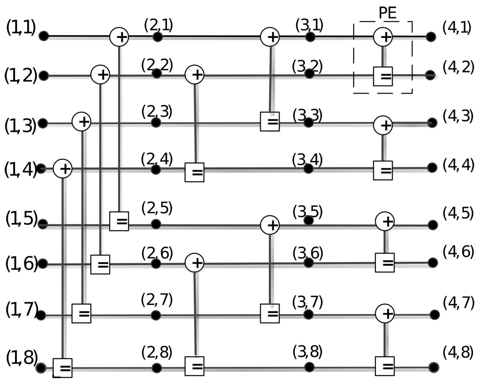
3.2. The Receiver Based on Modified BP Algorithm

For the proposed SLM receiver, some modifications are required to identify the transmitted sequences without the need for SI. The proposed SLM receiver uses a BP-GF algorithm to perform the detection and decoding. The differences between the proposed BP-GF algorithm and the original BP algorithm are shown in the three functions of Algorithm 1.
Firstly, Initialization() performs the initialization of the BP-GF algorithm. The leftmost R -messages contain the information bits, the frozen bits and the PAPR bits. The rightmost L -messages represent the channel LLR L ch . These messages are initialized as
L n + 1 , j 0 = ln P x j = 0 | y j P x j = 1 | y j R 1 , j 0 = 0 , j I K , j F K j P and u p j = 0 K j P and u p j = 1
R 1 , j 0 = 0 is set for information indices j, indicating that the a priori probabilities for 0 and 1 are equal. R 1 , j 0 = K is set for the frozen indices j as the decoder knows that these indices are set to 0, where K is a large number (we set K = 100 in our simulation). The R -message corresponding to the PAPR set is initialized as K or −K, depending on the PAPR preset bit. All other R i , j 0 and L i , j 0 are set to 0. The Initialization() procedure will clear all stage messages and use new PAPR bits for the input of R -message in the next round of BP iterations. Note that the number 100 indicates a very high reliability in the LLR domain.
Algorithm 1 BP-GF
Input: LLR channel output L ch and I , F , P , PAPRbits
Output: estimated information bits u ^ ( q )
1:
for  q = 1 : Q   do
2:
    L , R ← Initialization L ch , I , F , P , PAPRbits ( q )
3:
   Set i I = 1 and F l a g = 1
4:
   while  i I I t e r m a x and F l a g = 1 do
5:
      L , R are updated as Equations (2)
6:
     if  i I 2 n  then
7:
         u ^ and x ^ are assigned by Equations (3)
8:
        if GFcheck L , R  then
9:
           F l a g = 0
10:
        end if
11:
     end if
12:
   end while
13:
   if  F l a g = 0  then
14:
     return u ^ ( q )
15:
     break
16:
   end if
17:
end for
18:
if  F l a g = 1  then
19:
    u ^ ( q ) MinEuclideanDistance y , x ^
20:
end if
21:
return u ^ ( q )
Secondly, the proposed BP-GF algorithm adopts a detection method that includes the G-matrix-based ETC and verification of the sum of estimated frozen bits u ^ F . The former reduces the decoding latency, while the latter maintains the error-correction performance. This detection procedure is called GFcheck() and is shown in Algorithm 2. When GFcheck() is successively met, the decoding process stops, and the receiver outputs the q ^ -th decoded result. If GFcheck() does not succeed within one round of iterations, the next round of iterations is started.
Algorithm 2 GFcheck
Input: L , L-matrix of BP factor graph
             R , R-matrix of BP factor graph
Output: isSatisfied
1:
u ^ LLR 2 bit L 1 , : + R 1 , :
2:
x ^ LLR 2 bit L n + 1 , : + R n + 1 , :
3:
if  x ^ = encode u ^ , G & & sum ( u ^ F ) = 0  then
4:
   return true
5:
end if
6:
return false
Finally, if there is no valid check after Q rounds of BP iteration, MinEuclideanDistance() is calculated between all estimated codewords x ^ and the received signal y as follows:
u ^ ( q ) = arg min q | | y x ^ | | .
As a result, the q ^ -th path with the minimum Euclidean distance is selected as the decoded result.

4. Simulation Results

In this section, we evaluate the performance of the proposed PC-SLM scheme with BPSK modulation over the additive white Gaussian noise (AWGN) channel and the International Telecommunication Union (ITU) Pedestrian B fading channel using MATLAB R2020a. We set the code length to 1024 and the code rate to 0.5. The Bhattacharyya bound [1] is used to determine the information set I . The PAPR set P and P q are obtained offline.

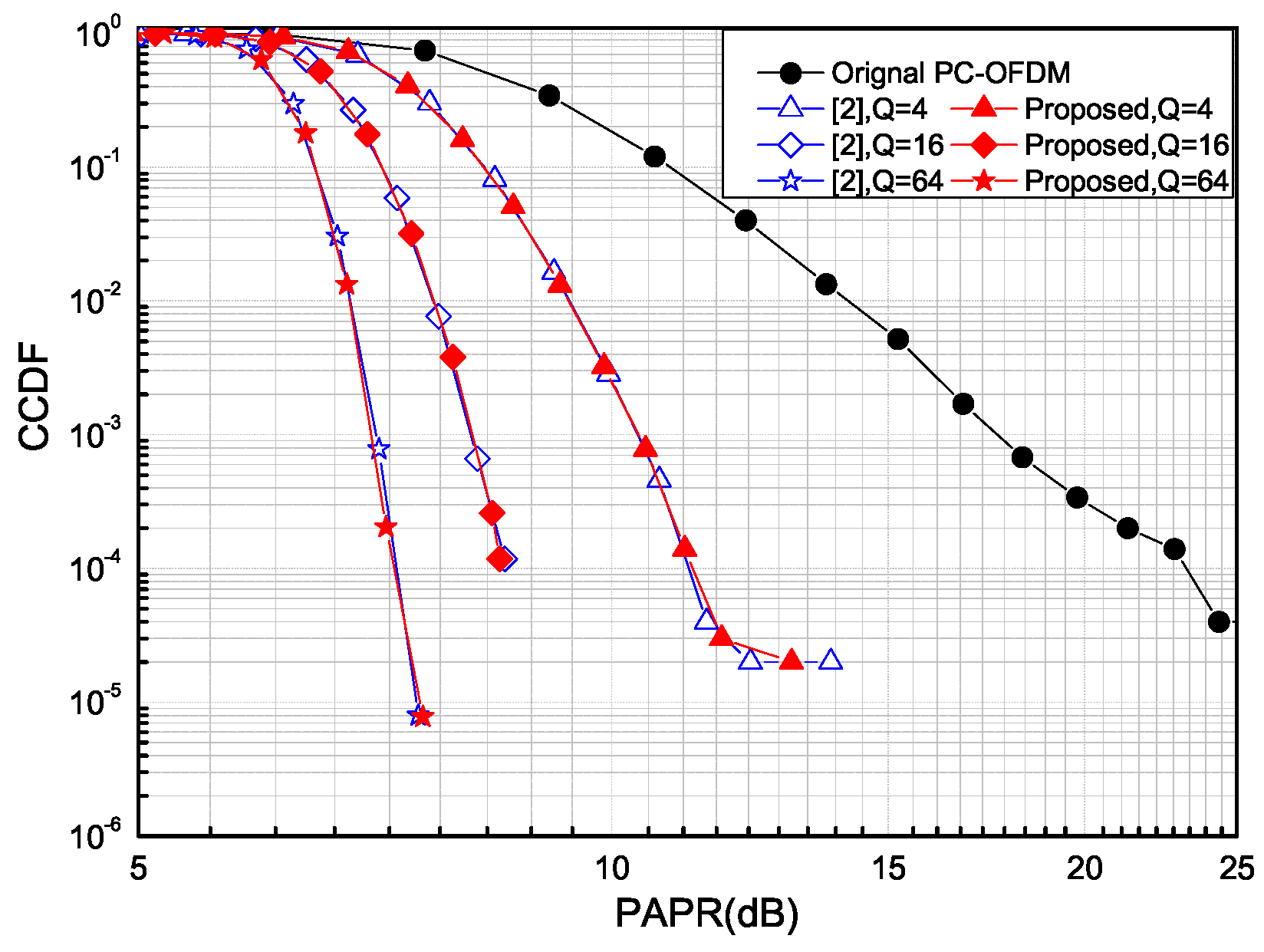
4.1. PAPR Performance

We use the complementary cumulative distribution function (CCDF) to measure the performance of PAPR reduction. The PAPR reduction performance of the proposed scheme is presented in Figure 3 and Figure 4, using the number of candidates Q { 4 , 16 , 64 } for N = 1024 and N = 128, respectively. The proposed scheme achieves significant PAPR reduction compared to the non-SLM scheme for different code lengths N, with the gain increasing as the number Q of PAPR bits increases. Specifically, for N = 1024, the proposed PAPR reduction method with Q { 4 , 16 , 64 } offers significant gains of approximately 9.2, 14.3 and 15.2 dB, respectively, over the original polar-coded–OFDM (PC-OFDM) without PAPR reduction at the CCDF of 10 4 . Compared with the PAPR reduction performance in [2], our proposed scheme demonstrates an equivalent PAPR performance.

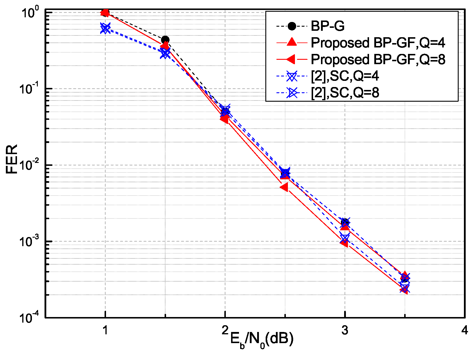
4.2. Frame Error Rate (FER) Performance

In Figure 5, we evaluate the FERs of the proposed BP-GF-based receiver over the AWGN channel, where the maximum number of iterations is set to 60. As a benchmark for comparison, we evaluate the performance of the original BP algorithm with G-matrix-based ETC (BP-G) in the PC-OFDM system, and SC-based receiver of [2]. In the simulation, the number of candidates is set to Q { 4 , 8 } for the SLM schemes. Compared to the BP-G algorithm over AWGN channels, the BP-GF-based receiver achieves a consistent FER performance for Q = 4 and, for Q = 8, it provides a 0.3 dB signal-to-noise ratio (SNR) gain at FER = 10 3 .
Figure 6 illustrates the FER performance of the proposed BP-GF-based receiver compared with the BP-G algorithm and SC-based receiver of [2] over the Pedestrian B fading channel. A cyclic prefix (CP) of length 16 is applied to each transmission block, and the channel impulse response (CIR) of the ITU Pedestrian B model is shown in Table 2. The results obtained show that the performance of the proposed BP-GF algorithm is better than that of BP-G for Q = 4 or 8. The proposed method provides 0.5 dB SNR gain at FER = 8 · 10 2 .
In the PC-SLM scheme, the error correction performance depends on both the SLM design and polar coding. Since the SC and BP algorithms exhibit a comparable decoding performance in the same channel, their error performance remains consistent under SLM schemes with similar PAPR reduction capabilities. The proposed BP-GF-based receiver achieves an error correction performance comparable to the SC-based receiver in [2], as both SLM transmitters employ the partially frozen bit method. The use of PAPR bits in the BP-GF algorithm is analogous to adding a small amount of noise, allowing the decoder to handle errors due to the lack of convergence in the noise-aided BP list decoder [9].

4.3. Latency Analysis

A PE is used to update the LLR message at each clock cycle. In this subsection, for simplicity, we focus on the implementation of the LLR update function (boxplus operator), the most time consumption, and the number of clock cycles needed is referred to as the decoding latency.
For a fair comparison, the implementation of the BP and SC decoder is based on pipelining [10,11]. In general, for an ( N , K ) BP decoder with n stages of PEs, each stage contains N / 2 PEs to update the LLR messages. PEs are activated stage by stage from left to right in each iteration, and the decoding latency is n · I t e r m a x cycles [12]. Considering that the G-matrix ETC leads to an additional latency of two clock cycles [12], the decoding latency for the BP decoder with G-matrix ETC is n · I t e r a v e r + 2 cycles.
Table 3 shows the average iteration number with Q ( I t e r Q a v e r ) of the proposed BP-GF algorithm in the SLM scheme on the AWGN channel. Regardless of the code length (128 or 1024), the I t e r Q a v e r decreases rapidly as the SNR increases, with a more significant reduction observed for N = 1024. For N = 1024, starting from an SNR of 2.5 dB, I t e r Q a v e r for Q = 8 becomes similar to that for Q = 4. In the high SNR region, the benefit of reducing I t e r Q a v e r is particularly significant. When SNR is 3.5 dB, I t e r Q a v e r can be reduced by 96% for Q = 8.
For the SC decoder, the pipelined tree architecture with a reduced number of PEs and registers requires 2 N 2 cycles [13]. Since an ( N , K ) SCL decoder can be viewed as the combination of L copies of ( N , K ) SC decoders, an ( N , K ) SCL decoder also requires ( 2 N 2 ) cycles to process its LLR update function. Additionally, an extra N cycles are required to sort 2 L path metrics and select the L largest metrics for each decoded bit in the SCL decoders. Therefore, the decoding latency of an ( N , K ) SCL decoder is 3 N 2 cycles [14].
To compare the decoding latency between the proposed BP-GF-based SLM scheme and the SCL-based SLM scheme with Q candidates, we define the ratio as
T S L M S C L T S L M B P G F = Q · ( 3 N 2 ) n · I t e r Q a v e r + 2
In the SLM-SCL scheme, the total processing time is Q times that of a single SCL algorithm run. However, in the proposed SLM-BP-GF scheme, it depends on I t e r Q a v e r , as shown in Table 3, which is determined by simulation.
Figure 7 illustrates the decoding latency ratio of the SCL-based receiver [3,4] relative to the BP-GF-based receiver. The simulation results show that this ratio increases with code length (from N = 128 to N = 1024) and grows rapidly with SNR. Specifically, for N = 1024, Q = 8 and SNR = 3.5 dB, the SCL-based receiver suffers from significantly higher decoding latency, with its latency 120 times higher than that of the BP-GF-based receiver, making it inefficient for practical applications.

5. Conclusions

This paper presents a modified PC-SLM scheme for PAPR reduction. By exploiting the coset code property, a single polar encoder and modulator generate multiple modulation symbols, significantly reducing the hardware complexity compared to existing PC-SLM schemes. For the PC-SLM scheme employing the partially frozen bit method, the proposed BP-GF-based receiver achieves a significant PAPR reduction and error correction performance, comparable to that of the SC-based receiver. Furthermore, the BP-GF-based receiver exhibits a lower decoding latency than the SCL-based receiver, with latency reduction becoming more pronounced as the code length increases. Future work will focus on optimizing the selection of PAPR bits and extending the proposed approach to various channel conditions to enhance its applicability in next-generation wireless communication systems.

Author Contributions

Writing—original draft preparation, C.X.; writing—review and editing, N.C.H.; supervision, A.G.A. All authors have read and agreed to the published version of the manuscript.

Funding

This research was funded by Research Foundation for Advanced Talents of Henan University of Technology (Grant No. 2021BS005).

Institutional Review Board Statement

Not applicable.

Informed Consent Statement

Not applicable.

Data Availability Statement

Data are contained within the article.

Conflicts of Interest

The authors declare no conflicts of interest.

References

  1. Arikan, E. Channel Polarization: A Method for Constructing Capacity-Achieving Codes for Symmetric Binary-Input Memoryless Channels. IEEE Trans. Inf. Theory 2009, 55, 3051–3073. [Google Scholar] [CrossRef]
  2. Matsumine, T.; Ochiai, H. A Novel PAPR Reduction Scheme for Polar-Coded OFDM Systems. IEEE Commun. Lett. 2019, 23, 2372–2375. [Google Scholar] [CrossRef]
  3. Zhang, S.-Y.; Shahrrava, B. A SLM Scheme for PAPR Reduction in Polar Coded OFDM-IM Systems Without Using Side Information. IEEE Trans. Broadcast. 2021, 67, 463–472. [Google Scholar] [CrossRef]
  4. Lim, S.-C.; Kim, N.; Park, H. Polar Coding-Based Selective Mapping for PAPR Reduction Without Redundant Information Transmission. IEEE Trans. Broadcast. 2020, 24, 1621–1625. [Google Scholar] [CrossRef]
  5. Zhang, S.-Y.; Yue, X.; Shahrrava, B.; Zhang, Y.; Wang, G. A Polar-Coded PAPR Reduction Scheme Based On Hybrid Index Modulation. IEEE Open J. Commun. Soc. 2024; early access. [Google Scholar] [CrossRef]
  6. Tal, I.; Vardy, A. How to construct polar codes. IEEE Trans. Inf. Theory. 2013, 59, 6562–6582. [Google Scholar] [CrossRef]
  7. Arikan, E. Polar codes: A pipelined implementation. In Proceedings of the 2010 IEEE International Symposium on Broadband Communication, Melaka, Malaysia, 11–14 July 2010. [Google Scholar]
  8. Yuan, B.; Parhi, K.K. Early Stopping Criteria for Energy-Efficient Low-Latency Belief-Propagation Polar Code Decoders. IEEE Trans. Signal Process. 2014, 62, 1285–1288. [Google Scholar] [CrossRef]
  9. Çağrı Arlı, A.; Gazi, O. Noise-Aided Belief Propagation List Decoding of Polar Codes. IEEE Commun. Lett. 2019, 23, 1285–1288. [Google Scholar] [CrossRef]
  10. Zhang, C.; Yang, J.; You, X.; Xu, S. Pipelined implementations of polar encoder and feed-back part for SC polar decoder. In Proceedings of the 2015 IEEE International Symposium on Circuits and Systems, Lisbon, Portugal, 24–27 May 2015; pp. 3032–3035. [Google Scholar]
  11. Yang, J.; Zhang, C.; Zhou, H.; You, X. Pipelined belief propagation polar decoders. In Proceedings of the 2016 IEEE International Symposium on Circuits and Systems, Montreal, QC, Canada, 22–25 May 2016; pp. 413–416. [Google Scholar]
  12. Yuan, B.; Parhi, K.K. Architecture optimizations for BP polar decoders. In Proceedings of the 2013 IEEE International Conference on Acoustics, Speech and Signal Processing, Vancouver, BC, Canada, 26–31 May 2013; pp. 2654–2658. [Google Scholar]
  13. Leroux, C.; Tal, I.; Vardy, A.; Gross, W.J. Hardware architectures for successive cancellation decoding of polar codes. In Proceedings of the 2011 IEEE International Conference on Acoustics, Speech and Signal Processing, Prague, Czech Republic, 22–27 May 2011; pp. 1665–1668. [Google Scholar]
  14. Balatsoukas-Stimming, A.; Raymond, A.J.; Gross, W.J.; Burg, A. Hardware Architecture for List Successive Cancellation Decoding of Polar Codes. IEEE Trans. Circuits Syst. II Exp. Briefs. 2014, 61, 609–613. [Google Scholar] [CrossRef]
Figure 1. Factor graph corresponding to the generator matrix (N = 8).
Information 16 00384 g001
Figure 2. The proposed PC-SLM transmitter.
Information 16 00384 g002
Figure 3. The CCDFs of PAPR with N = 1024.
Information 16 00384 g003
Figure 4. The CCDFs of PAPR with N = 128.
Information 16 00384 g004
Figure 5. The FER performances with N = 1024 over AWGN channel.
Information 16 00384 g005
Figure 6. The FER performances with N = 1024 over ITU Pedestrian B fading channel.
Information 16 00384 g006
Figure 7. Ratio of decoding latency between the SLM-BP-GF scheme and the SLM-SCL scheme over AWGN channel.
Information 16 00384 g007
Table 1. Comparison of the proposed PC-SLM scheme with existing PC-SLM scheme.
SchemeConstruction (Offline)Frozen Bits UsedTransmitterReceiverSI Free
PC-SLM [2]1. set construction ( K + l )
2. PAPR sort ( K + l )
lQ encodersQ modulationQ IFFTSC
PC-SLM [3]set construction (K) N K one encoder
Q − 1 Scramble
Q modulationQ IFFTCA-SCL
PC-SLM [4]set construction (K) N K Q matrix productQ modulationQ IFFTSCL
Proposed PC-SLM1. set construction ( K + l )
2. Hamming weight of G I
3. PAPR sort ( < ( K + l ) )
lone encoder
Q − 1 AND operator
one modulationQ IFFTBP-GF
Table 2. CIR for the ITU Pedestrian B channel model.
Tap (samples)1310152743
Power level (dB)−3.92−4.82−8.82−11.92−11.72−27.82
Table 3. Average iteration number of the proposed BP-GF algorithm over AWGN channel.
SNR (dB)11.522.533.5
N = 128Q = 4100.1478.9759.4840.5426.8819.05
Q = 8189.98139.9294.5360.3438.0524.51
N = 1024Q = 4240168.6268.7227.0320.720.1
Q = 8480323.3286.327.320.6720.11
Disclaimer/Publisher’s Note: The statements, opinions and data contained in all publications are solely those of the individual author(s) and contributor(s) and not of MDPI and/or the editor(s). MDPI and/or the editor(s) disclaim responsibility for any injury to people or property resulting from any ideas, methods, instructions or products referred to in the content.

