Abstract
With the advancement of IT technology, intelligent devices such as autonomous vehicles, unmanned equipment, and drones are rapidly evolving. Consequently, the proliferation of defense systems based on these technologies is increasing worldwide. In response, the U.S. Department of Defense is implementing the RMF (Risk Management Framework) to ensure the cybersecurity of defense systems and conducting cybersecurity T&E (test and evaluation) concurrently. However, RMF and cybersecurity T&E conducted during the acquisition phase of defense systems often result in fragmented cybersecurity assessments, excluding the operational environment of the defense systems. This omission fails to account for the complex network integration, data exchange functionalities, and mission-specific requirements in actual cyber attack scenarios. For these reasons, vulnerabilities in defense systems that remain unidentified during the acquisition phase can potentially pose significant cybersecurity threats during operational phases, necessitating substantial costs and efforts for remediation. Therefore, this paper proposes a mission-based cybersecurity T&E model using a Multi-Cyber Range to effectively apply these two systems in a practical manner. The Multi-Cyber Range integrates independently operated cyber ranges into a network to expand the evaluation environment, which better reflects the mission environment of defense systems. The proposed model’s effectiveness is validated using a cyber attack simulation system targeting a virtualized arbitrary defense system. This paper not only presents an enhanced model for mission-based cybersecurity T&E, but also contributes to the advancement of cybersecurity T&E methodologies by providing a concrete application process.
1. Introduction
In recent times, there has been a steady increase in the emphasis on cybersecurity across various sectors, including private, public, and defense domains internationally. The U.S. Department of Defense is strengthening cybersecurity by developing the RMF (Risk Management Framework) as a next-generation cybersecurity framework and applying it to the entire life cycle of defense systems along with cybersecurity T&E (Test and Evaluation). Similarly, in South Korea, various security measures are being implemented at different stages of the defense system’s acquisition and operation. These measures include “reliability testing”, “interoperability assessment”, “security strategy review”, “security measurement”, “vulnerability analysis and evaluation”, and more. Different institutions are applying diverse security protocols to address potential cyber threats effectively.
In recent times, notable cybersecurity frameworks applied to defense systems within the international community include the United States’ RMF and cybersecurity T&E methodologies. These global trends are actively underway to enhance the cybersecurity of defense systems. As an illustrative example, ref. [1] proposed a mission-based cybersecurity T&E model integrated with the RMF for domestic application. Furthermore, ref. [2] introduced the concept of the Multi-Cyber Range, which amalgamates cyber ranges operated by each branch of the military to establish a comprehensive and immersive cyber training facility. This model aims to heighten fidelity and realism, facilitating three-dimensional joint training and interoperability assessments.
In addition, ref. [3] developed cybersecurity in the IoT environment, which is widely used in vehicles, industrial control, medical care, and national defense. For this, active research is in progress, such as proposing and simulating ransomware detection techniques.
Research on the application of mission-based cybersecurity T&E, in association with RMF and utilizing the Multi-Cyber Range, suggests a model that can be implemented by countries adhering to the RMF on an international scale. This model facilitates the execution of cybersecurity T&E procedures for defense system acquisition, enabling a more comprehensive assessment process within the Multi-Cyber Range environment.
The proposed model in this paper consists of four sequential stages, with each stage leveraging the utilization of the Multi-Cyber Range. In this paper, we define the proposed four-step process of the mission support system, focusing on a virtual defense system. During this process, we perform simulated experiments utilizing a cyber attack simulation system, specifically focused on the operational framework of the Multi-Cyber Range. These experiments are conducted based on a resource-depletion type of malicious code attack scenario. The role of the Multi-Cyber Range in this paper is to conduct simulated experiments using the same cyber attack simulation system utilized in [2].
The simulated experiments using the cyber attack simulation system are conducted throughout the proposed model’s stages, specifically from the third to the fourth stage, totaling four iterations. During the four iterations of simulated experiments, the evaluation assesses the severity of identified vulnerabilities, derives optimal protective measures, and verifies the effectiveness of the applied security measures. With confidence, we believe that these simulated experiments will demonstrate the same level of effectiveness when the proposed model is applied within the Multi-Cyber Range environment.
Following the introduction in Section 1, Section 2 discusses relevant studies, while Section 3 proposes the Multi-Cyber Range application model for cybersecurity T&E in association with the RMF. Subsequently, Section 4 describes the simulated experiments on a virtual mission support system, a representative defense system, to validate its effectiveness.
In Section 5, this paper presents its contributions, limitations, and future research directions.
2. Related Works
The related works within this study delve into the fundamental concepts and processes of the United States’ cybersecurity framework, known as the RMF, as well as the domain of cybersecurity T&E. These form the foundational backdrop against which the model proposed in this paper is situated. Furthermore, this section explores the pivotal concept of the Multi-Cyber Range, which serves as a central theme in our research. In addition to these discussions, we delve into the domain of MBCRA (Mission-based Cyber Risk Assessment). Here, we bring to light a significant issue: the existing guidelines in this area often lack specific execution methodologies. This underscores the paramount importance of the evaluation model and methodology that we concretize in this paper. They provide a solid foundation for deeper research in this field, emphasizing the need for a more comprehensive and practical approach.
2.1. RMF (Risk Management Framework)
In 2007, the U.S. DoD (Department of Defense) developed the RMF as an enhancement to the DIACAP (Department of Defense Information Assurance Certification and Accreditation Process). This development was undertaken to meet the requirements of the FISMA (Federal Information Security Management Act) effectively. The RMF is designed to perform cybersecurity risk management for all types of information systems in a technology-neutral manner. One advantage is that it does not require specific modifications for particular technologies. The RMF strengthens information security and enhances the risk management process.
It manages cybersecurity risks through a series of stages, including system categorization, security control selection, security control implementation, security control assessment, authorization, and monitoring [4].
In recent times, there has been a rapid and significant advancement in AI (artificial intelligence) technologies, leading to continuous progress in research related to ensuring cybersecurity reliability in AI-integrated systems. As a testament to this ongoing development, AI RMF 1.0 has been published, showcasing the dedication to enhancing cybersecurity measures in systems incorporating AI [5].
In particular, the U.S. Navy is actively conducting research on how to concretely implement cybersecurity and risk management for AI and machine learning applications during the process of acquiring naval defense systems [6]. Furthermore, research is underway on context-based adaptive RMF, which offers a more flexible, simpler, and easily implementable alternative to complex frameworks [7]. In the field of the IoT, [8] studied the IoT cyber risk management framework for human-centered vulnerabilities.
Consequently, in the future, there will be a growing demand for various model studies that provide specific and practical approaches to cybersecurity implementation. These studies will play a crucial role in offering concrete solutions for enhancing cybersecurity measures effectively.
2.2. Cybersecurity T&E (Test and Evaluation)
The United States applies cybersecurity T&E to various systems and domains, including defense business systems, national security systems, defense systems, and industrial control systems acquired by the U.S. DoD. This process commences before system deployment and continues throughout the entire lifecycle, with the objective of identifying and mitigating cybersecurity vulnerabilities that could potentially impact military capabilities.
Safety, survivability, and security are all encompassed within this goal. The early detection of system vulnerabilities enhances military resilience while aiding in cost, schedule, and performance optimization.
The cybersecurity T&E process consists of six phases, as follows [9]:
Phase 1. Understand Cybersecurity Requirements: Understand the cybersecurity, cyber survivability, and operational resilience requirements of a system.
Phase 2. Characterize the Cyber Attack Surface: Identify vulnerabilities and attack vectors that adversaries can use in cyber attacks to develop an assessment plan.
Phase 3. Cooperative Vulnerability Identification: Implement an assessment plan in a collaborative environment to identify vulnerabilities and determine necessary mitigation actions.
Phase 4. Adversarial Cybersecurity DT&E: Assess the cyber viability and operational resilience of systems in hostile environments.
Phase 5. Cooperative Vulnerability and Penetration Assessment: Use data during operational testing and evaluation to evaluate cybersecurity and system resilience from an operational perspective.
Phase 6. Adversarial Assessment: A certified red team evaluates the protection systems, layered defenses, and defense capabilities for critical missions.
The United States seamlessly integrates the RMF and cybersecurity T&E throughout the entire process of defense system acquisition. Figure 1 illustrates the step-by-step progression of the RMF and cybersecurity T&E in various phases of the U.S. military’s defense system acquisition process [10,11].
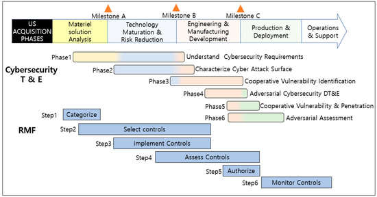
Figure 1.
U.S. military’s cybersecurity activities by phase of defense system development.
2.3. The Multi-Cyber Range
According to the NIST (National Institute of Standards and Technology) in the United States, a cyber range is defined as an interactive simulation of an organization’s local network, systems, tools, and applications. It provides a secure and lawful environment for acquiring real-world cybersecurity skills and conducting safe environments for development and security testing [12].
DARPA in the United States has been operating a cyber training range since 2009 and has further developed to facilitate its use in actual training and test evaluation, and the test space in the security area is connected to the cyber range to provide training and test evaluation in a multi-level security environment [13].
The cyber range was built to train procedures for analyzing threats in real-world environments based on cyber threat scenarios in a more real-world cyber–physical environment rather than a theoretical approach to cybersecurity education [14]. In addition to this, the cyber range was built with a mixture of physical equipment, simulation models, and emulation models to develop a distributed intrusion detection system applied to the industrial control system environment [15].
This Multi-Cyber Range comprehensively simulates the Joint Chiefs of Staff’s battlefield environment and each military branch’s tactical environment, enabling realistic and comprehensive assessments.
The Multi-Cyber Range is designed with a focus on the Joint Chiefs of Staff’s battlefield environment, where various sub-systems are interconnected using the LVC (Live Virtual Constructive) concept. This design facilitates mission-based cybersecurity training and defense system testing and evaluation, providing the capability to conduct comprehensive assessments. The Multi-Cyber Range concept involves the interconnection and information exchange among sub-ranges in a manner that closely resembles real-world environments.
The Multi-Cyber Range is composed of a main range and several sub-ranges. The main range facilitates training and evaluation activities, interconnecting with multiple sub-ranges while sharing resource states. Additionally, the sub-ranges are designed to operate independently, providing flexibility in their operations. The main range utilizes the Range Management Channel to oversee the management of sub-ranges, while the CDS (Cross-Domain Solution) securely controls the exchange of information through the Packet Flow Channel to accurately reflect the operational environment. Figure 2 illustrates the concept of interconnection and network within the Multi-Cyber Range in this paper.
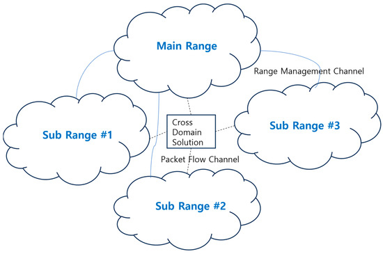
Figure 2.
Networking architecture for connecting ranges.
It is proposed that by constructing the Multi-Cyber Range to closely resemble real-world training environments, it enables practical training effectiveness and facilitates the evaluation of defense system acquisition’s interoperability during real-world scenarios. This paper suggests a hybrid approach that enhances efficiency by collecting actual operational traffic for training and interoperability evaluation. This approach involves the integration of a red team’s attack activities to create a realistic operational environment. Based on the consideration that interoperability evaluation is feasible, it is deemed possible to extend this capability for RMF assessment. Therefore, in this study, a model is proposed for conducting mission-based cybersecurity T&E within the Multi-Cyber Range.
In recent similar research cases, for IoT devices, due to the diversity of vendors, architectures, firmware, and other hardware, it has been proposed to construct a hybrid cyber range for IoT security. This hybrid approach combines digital emulators and actual hardware to enhance the effectiveness of IoT security testing and evaluation [16].
This form will serve as a valuable reference model for the Multi-Cyber Range in various defense systems composed of diverse embedded devices.
In addition, active research is being conducted on creating simulation environments for secure cybersecurity testing and evaluation in advanced connected cars, using virtual machines to assess security measures in a real-life environment. This demonstrates the ongoing efforts to establish realistic cybersecurity T&E environments [17].
2.4. MBCRAs (Mission-Based Cyber Risk Assessments)
MBCRAs (Mission-based cyber risk assessments) are a pivotal methodology for assessing and prioritizing cybersecurity risks in currently operational defense systems. The Department of Defense’s “DoDI 5000.89” directive mandates the utilization of this methodology throughout the developmental lifecycle of systems under development, emphasizing the importance of planning and testing within real-world contexts and mission impacts. However, these guidelines do not provide detailed instructions on how to evaluate the methodology [18].
As part of ongoing efforts to establish evaluation criteria for the MBCRA methodology, the IDA (Institute for Defense Analyses) has conducted recent research into MBCRA methodologies. Furthermore, there is an active investigation into which MBCRA methodologies are widely employed in the field of cybersecurity T&E.
In this paper, we present a concrete approach to mission-based cybersecurity T&E for defense systems, allowing for the consideration of real-world environments and mission impacts. This represents a significant advancement in addressing the limitations of previous guidelines, which have not provided specific evaluation methodologies.
We introduce a specific methodology that utilizes the Multi-Cyber Range as a means to achieve this.
Table 1 shows a comparison of the characteristics of defense system cybersecurity systems.

Table 1.
Comparison of characteristics of defense system cybersecurity systems.
In this paper, we model and introduce previously unaddressed collaboration and specific execution methodologies in defense system cybersecurity frameworks. We validate their effectiveness through limited simulations.
3. The Multi-Cyber Range Application of Cybersecurity T&E in Association with RMF
This paper proposes a model for conducting cybersecurity T&E, in association with the RMF, during the defense system acquisition process, utilizing the Multi-Cyber Range. The Multi-Cyber Range integrates independently operated cyber ranges from the Joint Chiefs of Staff and each military branch into a network, facilitating data exchange among interconnected segments, emulating the operational environment of actual defense systems. This approach provides a safe yet practical support for cybersecurity T&E. The proposed model is performed through the procedures of Step 1 (threat modeling), Step 2 (attack surface listing), Step 3 (attack surface-oriented vulnerability analysis and evaluation in the Multi-Cyber Range), and Step 4 (simulated penetration based on ROE in the Multi-Cyber Range). Figure 3 illustrates the four-stage procedure of the proposed model.
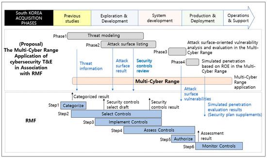
Figure 3.
Conceptual diagram of the Multi-Cyber Range application of cybersecurity T&E in association with RMF.
The details of each stage of the proposed model are as follows.
3.1. Threat Modeling
In the first phase, threat modeling, the defense system is divided into layers based on assets, functions, operational tasks, and missions. For each layer, potential threats from an attacker’s perspective are identified, and expected threat scenarios are derived. This process aims to enhance the understanding of potential risks and vulnerabilities throughout the defense system’s structure. During this phase, the proposed model receives security classification results for the defense system from the RMF and utilizes the Multi-Cyber Range to support the identification of potential threat scenarios’ components. By leveraging the capabilities of the Multi-Cyber Range, various elements within the threat scenarios are identified, enabling a comprehensive understanding of the system’s security vulnerabilities. This integration of the RMF and the Multi-Cyber Range enhances the accuracy and effectiveness of the threat-modeling process, contributing to a more robust cybersecurity evaluation for the defense system.
3.2. Attack Surface Listing
In the second phase, the model focuses on listing and specifying the attack surfaces of the defense system. These attack surfaces represent the entry points through which external attackers can access the cyber domain of the defense system. By thoroughly identifying and detailing these attack surfaces, the model gains a comprehensive understanding of the system’s potential vulnerabilities, which is crucial for conducting effective cybersecurity evaluations. The Multi-Cyber Range plays a pivotal role in facilitating this process, as it enables a realistic and secure environment for assessing the identified attack surfaces and their potential impact on the system’s security. The compiled list of attack surfaces is provided to the RMF for consideration during the selection of security control items. By doing so, the model ensures that the identified attack surfaces and potential threats are appropriately accounted for when determining the security control measures. Through a thorough review and evaluation of the initial selection of security control items, additional enhancements and measures to bolster the system’s security are identified. The collaboration between the proposed model and the RMF helps to ensure a comprehensive and robust cybersecurity evaluation, ultimately strengthening the overall security posture of the defense system. In the Multi-Cyber Range, threat scenarios are developed by simulating the attack surface and specifying the process of inflow and propagation of cyber threats, and the developed threat scenarios can be supplemented by feedback to the selection of security control items.
3.3. Attack Surface-Oriented Vulnerability Analysis and Evaluation in the Multi-Cyber Range
In the third phase, attack surface vulnerability analysis and evaluation, is to identify vulnerabilities on the attack surface in connection with the RMF’s third step, security control item evaluation. Attack surface vulnerability information is provided in the RMF step 3 and used for security control item evaluation to analyze mission impacts by drawing vulnerable assets, functions, operational tasks, and missions based on identified vulnerabilities using the Multi-Cyber Range, and conducting simulations based on threat scenarios. It derives protection measures to mitigate the mission impact on cyber threats, and selects the most effective protection measures by repeating simulations for each possible protection measure.
3.4. Simulated Penetration Based on ROE in the Multi-Cyber Range
In the fourth phase, rule-of-engagement-based simulated penetration using the Multi-Cyber Range is performed in conjunction with the RMF step 4, security control item evaluation, and simulated penetration is conducted in the Multi-Cyber Range by setting threat scenarios for each attack surface as rules of engagement. In order to verify the effectiveness of the protection measures by using the Multi-Cyber Range, the effectiveness of the protection measures is verified by conducting the simulation again using the threat scenario as a rule of engagement while the protection measures are supplemented. Verification results are used for the adjustment of RMF security control items, defense system approval, and future supplementary plan establishment. At this time, when weaknesses are continuously identified or the effectiveness of protective measures is evaluated to be insufficient, the safe state of the defense system can be guaranteed by performing re-verification through retesting to ensure the defense system’s safety before deployment. In addition, by setting the threat scenario that can occur in the defense system as a rule of engagement, rather than a random simulated infiltration, it becomes a standard for effective cybersecurity T&E to ensure the cyber safety of the defense system.
4. The Multi-Cyber Range Simulation for Virtual “Mission Support System”
In this chapter, a virtual defense system, “Mission Support System” is defined, and a simulation experiment is conducted to apply cybersecurity T&E associated with the RMF to the Multi-Cyber Range. The simulation in this paper replaces the Multi-Cyber Range and uses the same cyber attack simulation system as the simulation method conducted in [2]. The mission support system, a virtual defense system, is defined to be “a system that requests operational support effectively from lower echelons to upper echelons using enemy information and target information” to identify missions, operational tasks, functions, and assets. Based on this, the procedure of the proposed model is performed step by step.
Phase 1, threat modeling, performs RMF security classification, identifies threats by layer of the mission support system, and identifies expected threat scenarios. Phase 2, attack surface cataloging, specifies the RMF security control items and attack surface. Phase 3, attack surface-based vulnerability testing and evaluation in the Multi-Cyber Range, identifies vulnerabilities on the attack surface and conducts first and second simulations of resource depletion-type malicious code attack scenarios using a simulation system. Through this, the mission impact is derived by identifying vulnerable assets, functions, operational tasks, and missions. Through the third simulation, possible protection measures against cyber threats are reviewed to derive the optimal protection measures. In phase 4, simulated penetration based on ROE in the Multi-Cyber Range, the effectiveness of the protection measures is verified by conducting the fourth simulation experiment with the previously identified threat scenarios as the rules of engagement and with the protection measures in place.
The specific details of each step are as follows.
4.1. Threat Modeling of “Mission Support System”
In the first phase, threat modeling for the mission support system defines the defense system by dividing it into layers of assets, functions, operational tasks, and missions, and identifies threats. The results of threat modeling are shown in Table 2.

Table 2.
Classification of “Mission support system” by hierarchy.
In step 1 of the RMF, the mission support system is defined as a system that conducts operations based on enemy and target information. Therefore, the security classification of the mission support system is classified as “high” for confidentiality, “high” for integrity, and “medium” for availability, considering the information [19]. A total of 169 security control items were selected based on this in the second stage of the RMF, as shown in Table 3 [20].

Table 3.
Selected security control items.
If each layer of the virtual mission support system is divided into the mission range of the Multi-Cyber Range, it is shown in Figure 4.
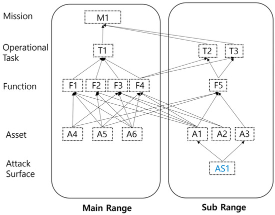
Figure 4.
Classification of mission support system layer into the Multi-Cyber Range.
4.2. Attack Surface Listing of “Mission Support System”
In the second phase, the mission support system layer is divided into mission, operation task, function, and asset to identify resource depletion-type malware attack threats using the attack surface. A cyberthreat enters through the attack surface, and a threat scenario is specified by identifying an asset and a possible propagation path. Figure 5 shows the attack surface, inflow path, and possible propagation path in the Multi-Cyber Range.
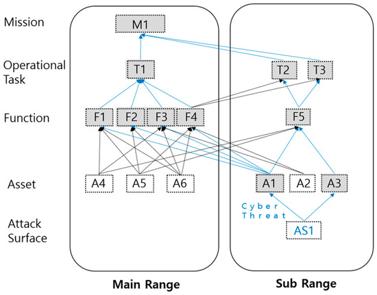
Figure 5.
Attack surface shown in the Multi-Cyber Range, inflow path, and path through which cyber threats can propagate.
4.3. Attack Surface-Oriented Vulnerability Analysis and Evaluation
In the third phase, vulnerability analysis and evaluation on the attack surface of the mission support system identifies vulnerabilities, and simulates a threat scenario in which a resource depletion-type malware attack occurs, targeting the attack surface in the cyber attack simulation system.
Connectable paths are identified for each hierarchical node of the mission support system, and random weights are assigned to each path as shown in Table 4, considering the characteristics of the mission.

Table 4.
Weight by node path.
In order to evaluate the impact on the mission of each asset node, a correlation matrix, such as Equations (1)–(3), is defined.
In this case, means the degree of influence of elements of set X on elements of set Y. In order to determine the influence of the lower node from the viewpoint of the upper node, the normalization process as shown in Equation (4) is performed.
Equations (5)–(7) show the effect of operational tasks on missions, functions on operational tasks, and assets on functions, respectively.
The impact of the asset on the mission can be calculated as in Equation (8), and the result is as in Equation (9).
From this, it can be seen that the asset that has the most impact on the mission is A3, and the asset that has the least impact is A4. In this paper, the impact on the mission is quantified by generating an IER (information exchange requirement) according to the degree of influence from the lower node to the upper node. Figure 6 shows the amount of IER received from the asset node to the functional node. The asset node generates an IER equal to the weight of each function X 10 Kbps (exponential distribution), and it is the result of measuring the average IER received per function.
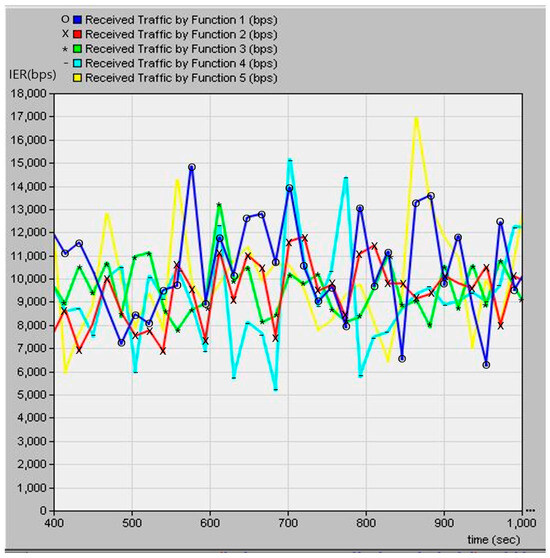
Figure 6.
Received IER volume per function sent by assets.
Table 5 shows the statistical values of IERs received by functional nodes from asset nodes. As a result of the simulation, it can be confirmed that all functional nodes receive IERs of about 10 kbps.

Table 5.
Statistics of received IERs per function sent by assets.
Figure 7 shows the IER received by the task nodes from the function nodes.
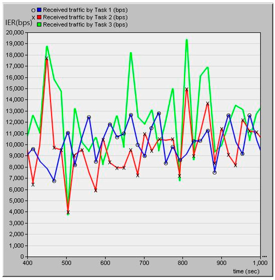
Figure 7.
IER volume received to task nodes sent by function nodes.
The function node forwards IER X weight X 10 kbps received from the asset node to the task node. Therefore, the task node must receive an IER of about 10 kbps in the normal state. As a result of the simulation, it can be confirmed that all operational task nodes receive an IER of 10 kbps on average.
Figure 8 is the result of measuring the IER received by the task node for each task node.
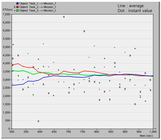
Figure 8.
IER volume received by mission node at normal state. (Line means average value and dot means instant value.).
The line is the average IER received by the task node for each operational task node, and the point is the instantaneous IER value. As a result of the measurement, it can be confirmed that the task node normally receives an IER of about 3.3 kbps for each operation task node. The second simulation test uses the identified attack surface to perform a resource depletion-type malware attack; measures the IER of each node; identifies vulnerable assets, functions, operational tasks, and missions; and derives the impact on the mission. Figure 9 is the IER of a mission node under malware attack.
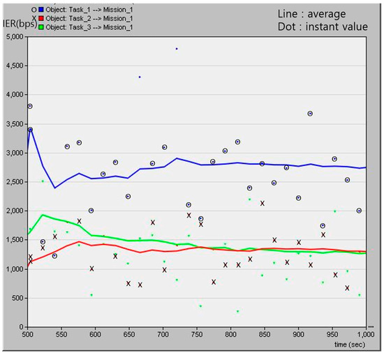
Figure 9.
IER volume received by mission node when asset 1 and 3 are compromised by malware attack. (Line means average value and dot means instant value.).
Through Equation (9), a resource depletion-type malware attack is performed on A1 and A3, which are the assets that have the highest impact on the mission, and the IER reception amount of the mission node is shown in Figure 9.
Comparing Figure 8 and Figure 9, it can be seen that when asset 1 and asset 3 are attacked, operational tasks T2 and T3 are most affected. Figure 10 shows the amount of IERs received by mission nodes and operational task nodes with and without cyber attacks.
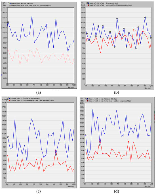
Figure 10.
(a) Received IER at mission node. (b) Received IER at Task1 node. (c) Received IER at Task2 node. (d) Received IER at Task3 node. (Blue line is normal situation and red line is cyber attack situation).
As a result of the simulation, when A1 and A3 were attacked, it was confirmed that the IER reception decreased by about 44.61% compared to the normal state (average IER reception in the steady state: 9655 bps, attack state: 5348 bps), and through this, the performance of the mission support system decreased to 56% compared to the normal state. In addition, it can be seen that T2 and T3 are most affected when subjected to a cyber attack.
Table 6 statistically shows the operation task and the IER reception of the mission node in the normal state without a cyber attack and the state in which a cyber attack occurred.

Table 6.
Statistics of received IER with and without cyber attack.
The third simulation experiment is conducted by supplementing the protection measures that can mitigate the impact of missions on resource depletion-type malicious code attacks, and through this, the optimal protection measures are derived. As protection measures to respond to resource depletion-type malicious codes, protection systems such as interlocking sections (e.g., firewall) and terminal protection systems such as anti-virus systems are classified and proposed as protection measures. Figure 11 is a configuration diagram supplemented with protective measures.
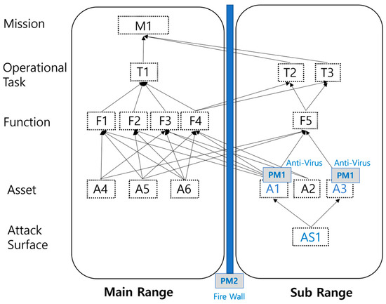
Figure 11.
Configuration diagram supplemented with protective measures.
Figure 12 is the result of measuring the IER received by the mission node from the operational task node when the derived protection measures are applied.
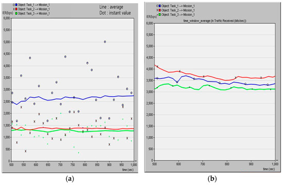
Figure 12.
(a) Interlocking section protection measures such as firewall. (b) Protection measures for terminals such as anti-virus.
As a result of the simulation, it can be confirmed that it is difficult to defend against attacks from resource depletion-type malicious codes with only the protection system of the interlocking section. It can be seen that the method of reinforcing the countermeasure against resource depletion-type malicious code is the method of detecting and blocking abnormal behavior at the terminal node where the attack surface exists. Based on these results, the optimal protection measures are selected and the RMF security control items are supplemented.
4.4. Simulated Penetration Based on ROE in the Multi-Cyber Range
In the fourth phase, simulated penetration based on ROE in the Multi-Cyber Range, the effectiveness of the protection measures is verified by conducting the fourth simulation experiment with the protection measures derived in the third step, complemented by taking the resource depletion-type malicious code attack on the previously identified attack surface as a rule of engagement.
Figure 13 is the result of measuring the IER reception of the mission node when a cyber attack is introduced with protection measures applied.
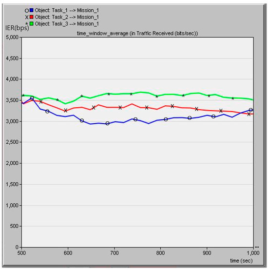
Figure 13.
IER volume received by mission node after applying protection measures.
4.5. Summary of Simulation Results
In Chapter 4, a virtual defense system, “Mission Support System” was defined, and the proposed Multi-Cyber Range application model of cybersecurity T&E while carrying out the RMF procedure was simulated using a cyber attack simulation system. A total of four simulations were conducted over the third and fourth stages of the cybersecurity T&E proposed in this paper. Through the first and second simulation experiments, it was possible to judge the operational impact on cyber threats by performing a resource depletion-type malware attack on the attack surface. Optimal protection measures could be selected through the third simulation experiment, and the fourth simulation experiment confirmed the effectiveness of the protection measures derived by taking the resource depletion-type malware attack scenario as a rule of engagement according to the fourth stage, simulated penetration based on ROE in the Multi-Cyber Range. Table 7 shows the comparative evaluation of the strengths of the model proposed in this paper and similar studies conducted in the past.

Table 7.
Comparison of strengths of previous studies and the proposed model.
Table 8 shows the comparative evaluation of previous studies and the proposed model in terms of performance.

Table 8.
Comparison of strengths of previous studies and the proposed model.
5. Conclusions
In this paper, we propose a model that applies mission-based cybersecurity T&E, in association with the RMF, to the Multi-Cyber Range. This model can be applied by all countries implementing the RMF during the defense system acquisition phase and supports practical cybersecurity testing and evaluation by integrating and enhancing the currently operational cyber ranges.
In particular, this study was able to propose a specific application model for the Multi-Cyber Range by conducting simulations using a cyber attack simulation system. This serves as a practical approach to applying cybersecurity to emerging defense systems.
The proposed model measured the impact of cyber attacks on the attack surface through simulations of resource-depleted malware. Based on this, optimal protective measures were derived through comparative evaluations of possible protection measures. The effectiveness of the derived protection measures was verified through a simulation experiment, establishing them as standards for cybersecurity T&E during defense system acquisition and improving the cybersecurity of the defense system.
The vulnerabilities and protective measures identified through the simulation experiment will be integrated into the security control items of the RMF. This integration ensures that cybersecurity T&E and the RMF can complement each other organically, further enhancing the cybersecurity of the defense system.
This paper has contributed to the development of research in the field of researching or operating cybersecurity systems by conducting simulations that apply core cybersecurity activities performed in the defense system acquisition stage to virtual defense systems. The method proposed in this paper can be used dually in the civil and defense sectors and will not cause any harm.
In future research, we will study a hybrid cybersecurity T&E model that links the Multi-Cyber Range with various modeling and simulation (M&S) systems operated by the military. This approach will enable more practical and secure cybersecurity T&E, conducted separately from actual defense systems, and strive to materialize plans to actively respond to cyberthreats. As predicted in [21], these efforts are expected to apply even digital twin technology to cyber range construction technology in the near future.
We explain the potential dual uses of this technology and that it is harmless.
Author Contributions
Conceptualization, I.K., M.P. and D.S.; Methodology, I.K., M.P., J.J. and D.S.; Software, I.K., M.P. and H.-J.L.; Validation, I.K., M.P., H.-J.L., J.J., S.L. and D.S.; Formal analysis, I.K., M.P., H.-J.L., J.J. and S.L.; Investigation, I.K., H.-J.L., J.J. and S.L.; Writing—original draft, I.K.; Writing—review & editing, D.S.; Supervision, D.S.; Project administration, D.S.; Funding acquisition, D.S. All authors have read and agreed to the published version of the manuscript.
Funding
This work was supported by the National Research Foundation of Korea (NRF) grant funded by the Korea government (MSIT) (No. 2022R1F1A1074773).
Data Availability Statement
The data presented in this study are available in article.
Conflicts of Interest
The authors declare no conflict of interest.
Dual-use Research Statement
This paper investigates Multi-Cyber Range and cybersecurity test and evaluation methodologies. This study is limited to providing some theoretical and experimental support for the development of cybersecurity test and evaluation models and does not pose any threat to cybersecurity or national security. This research is limited to academic areas that are beneficial for cybersecurity advancement. There is no risk to the general public. As an ethical responsibility, we strictly adhere to relevant national and international laws about dual-use research and we have considered and adhered to these regulations in our paper.
References
- Kim, I.; Kim, S.; Kim, H.; Shin, D. Mission-Based Cybersecurity Test and Evaluation of Weapon Systems in Association with Risk Management Framework. Symmetry 2022, 14, 2361. [Google Scholar] [CrossRef]
- Park, M.; Lee, H.; Kim, Y.; Kim, K.; Shin, D. Design and Implementation of Multi-Cyber Range for Cyber Training and Testing. Appl. Sci. 2022, 12, 12546. [Google Scholar] [CrossRef]
- Khalid Alkahtani, H.; Mahmood, K.; Khalid, M.; Othman, M.; Al Duhayyim, M.; Osman, A.E.; Alneil, A.A.; Zamani, A.S. Optimal Graph Convolutional Neural Network-Based Ransomware Detection for Cybersecurity in IoT Environment. Appl. Sci. 2023, 13, 5167. [Google Scholar] [CrossRef]
- NIST. Risk Management Framework for Information Systems and Organizations; NIST SP 800-37 Rev.2; NIST: Gaithersburg, MD, USA, 2018.
- NIST. Artificial Intelligence Risk Management Framework (AI RMF 1.0); NIST: Gaithersburg, MD, USA, 2023.
- Mun, J.; Housel, T. Artificial Intelligence and Machine Learning Applications to Navy Ships: Cybersecurity and Risk Management. Nav. Eng. J. 2023, 135, 1. [Google Scholar]
- Melaku, H.M. Context-Based and Adaptive Cybersecurity Risk Management Framework. Risks 2023, 11, 101. [Google Scholar] [CrossRef]
- Parsons, E.K.; Panaousis, E.; Loukas, G.; Sakellari, G. A Survey on Cyber Risk Management for the Internet of Things. Appl. Sci. 2023, 13, 9032. [Google Scholar] [CrossRef]
- Department of Defense. Cybersecurity Test and Evaluation Guidebook, Version 2.0 Change 1; U.S. Department of Defense: Arlington, VA, USA, 2020. Available online: https://daytonaero.com/wp-content/uploads/DOD_Cybersecurity-Test-and-Evaluation-Guidebook-Version2-C1_10-Feb-2020.pdf (accessed on 17 August 2023).
- Cybersecurity and Acquisition Lifecycle Integration Tool (CALIT). Available online: https://media.dau.edu/media/Cybersecurity+and+Acquisition+Lifecycle+Integration+Tool+%28CALIT%29/0_f8rabm9y (accessed on 18 August 2023).
- Whatmore, K. Cyber Resiliency Office for Weapon Systems: Systems Security Engineering Cyber Guidebook Version 4.0; Defense Technical Information Center: Fort Belvoir, VA, USA, 2021. [Google Scholar]
- NIST. National Initiative for Cybersecurity Education (NICE); NICE One Pager for Cyber Ranges; NIST: Gaithersburg, MD, USA, 2017.
- Oikonomou, N.; Mengidis, N.; Spanopoulos-Karalexidis, M.; Voulgaridis, A.; Merialdo, M.; Raisr, L.; Hanson, K.; Vallee, P.L.; Tsikrika, T.; Vrochidis, S.; et al. ECHO Federated Cyber Range: Towards Next-Generation Scalable Cyber Ranges. In Proceedings of the 2021 IEEE International Conference on Cyber Security and Resilience (CSR), Rhodes, Greece, 26–28 July 2021. [Google Scholar]
- Cruz, T.; Simões, P. Down the Rabbit Hole: Fostering Active Learning through Guided Exploration of a SCADA Cyber Range. Appl. Sci. 2021, 11, 9509. [Google Scholar] [CrossRef]
- Cruz, T.; Rosa, L.; Proença, J.; Maglaras, L.; Aubigny, M.; Lev, L.; Jiang, J.; Simoes, P. A cybersecurity detection framework for supervisory control and data acquisition systems. IEEE Trans. Ind. Inform. 2016, 12, 2236–2246. [Google Scholar] [CrossRef]
- Balto, K.E.; Yamin, M.M.; Shalaginov, A.; Katt, B. Hybrid IoT Cyber Range. Sensors 2023, 23, 3071. [Google Scholar] [CrossRef] [PubMed]
- Lee, D.-H.; Kim, C.-M.; Song, H.-S.; Lee, Y.-H.; Chung, W.-S. Simulation-Based Cybersecurity Testing and Evaluation Method for Connected Car V2X Application Using Virtual Machine. Sensors 2023, 23, 1421. [Google Scholar] [CrossRef] [PubMed]
- de Naray, R.K.; Buytendyk, A.M. Analysis of Mission Based Cyber Risk Assessments (MBCRAs) Usage in DoDs Cyber Test and Evaluation; Institute for Defense Analyses: Alexandria, VA, USA, 2022. [Google Scholar]
- NIST. Guide for Mapping Types of Information and Information Systems to Security Categories; NIST SP 800-60 Rev.1; NIST: Gaithersburg, MD, USA, 2008.
- NIST. Security & Privacy Controls for Federal Information Systems and Organizations; NIST SP 800-53 Rev.4; NIST: Gaithersburg, MD, USA, 2013.
- Chouliaras, N.; Kittes, G.; Kantzavelou, I.; Maglaras, L.; Pantziou, G.; Ferrag, M.A. Cyber Ranges and TestBeds for Education, Training, and Research. Appl. Sci. 2021, 11, 1809. [Google Scholar] [CrossRef]
Disclaimer/Publisher’s Note: The statements, opinions and data contained in all publications are solely those of the individual author(s) and contributor(s) and not of MDPI and/or the editor(s). MDPI and/or the editor(s) disclaim responsibility for any injury to people or property resulting from any ideas, methods, instructions or products referred to in the content. |
© 2023 by the authors. Licensee MDPI, Basel, Switzerland. This article is an open access article distributed under the terms and conditions of the Creative Commons Attribution (CC BY) license (https://creativecommons.org/licenses/by/4.0/).