
Power Control of Reed–Solomon-Coded OFDM Systems in Rayleigh Fading Channels


Abstract
1. Introduction
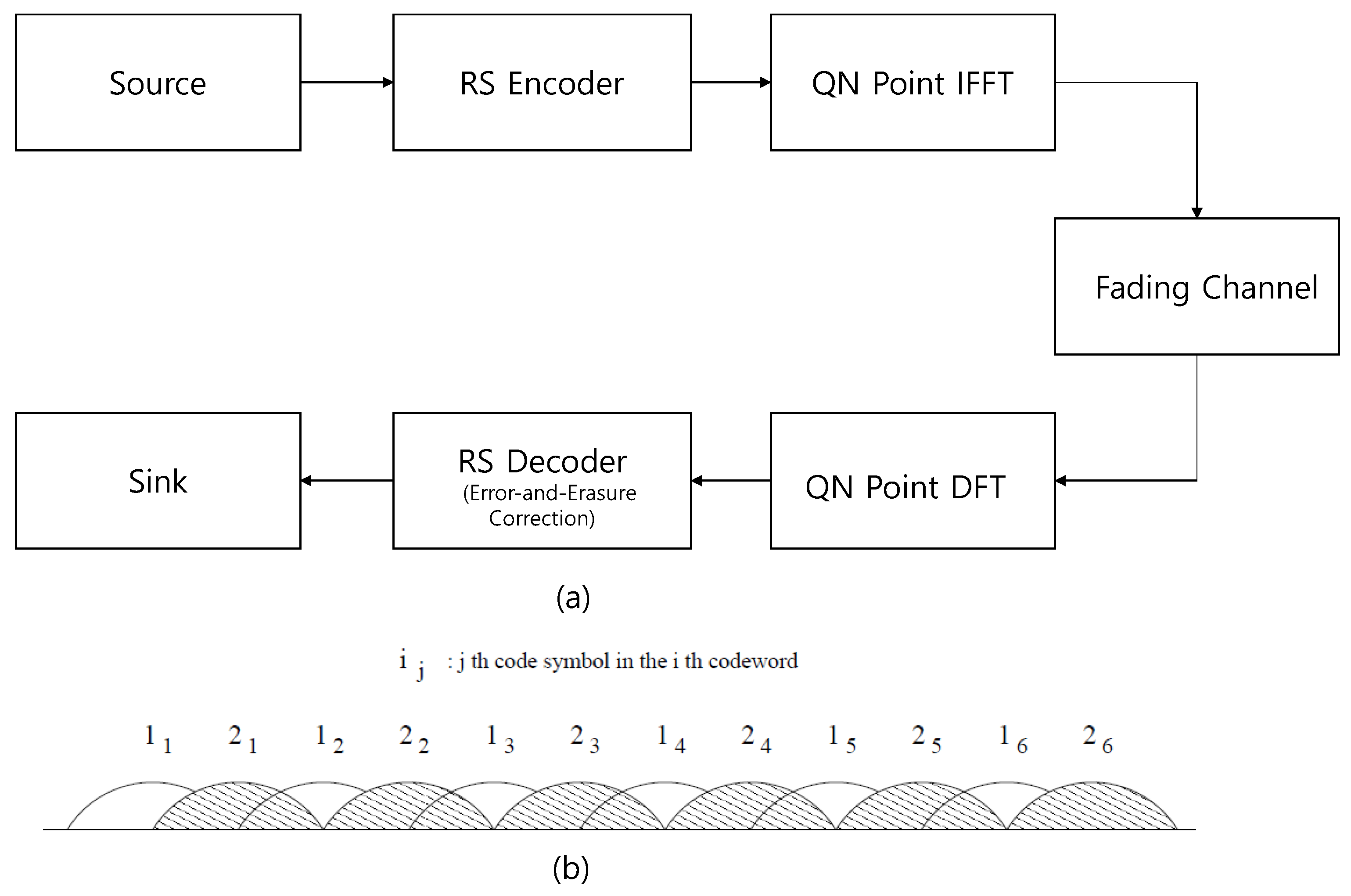
2. System Model
3. Truncated Channel Inversion
3.1. Erasure Generation by Ordering Fading Amplitudes
3.2. Erasure Generation by Comparing Fading Amplitudes with a Threshold
3.3. Erasure Generation by Ordering and Comparing Fading Amplitudes with a Threshold
4. Truncation Only
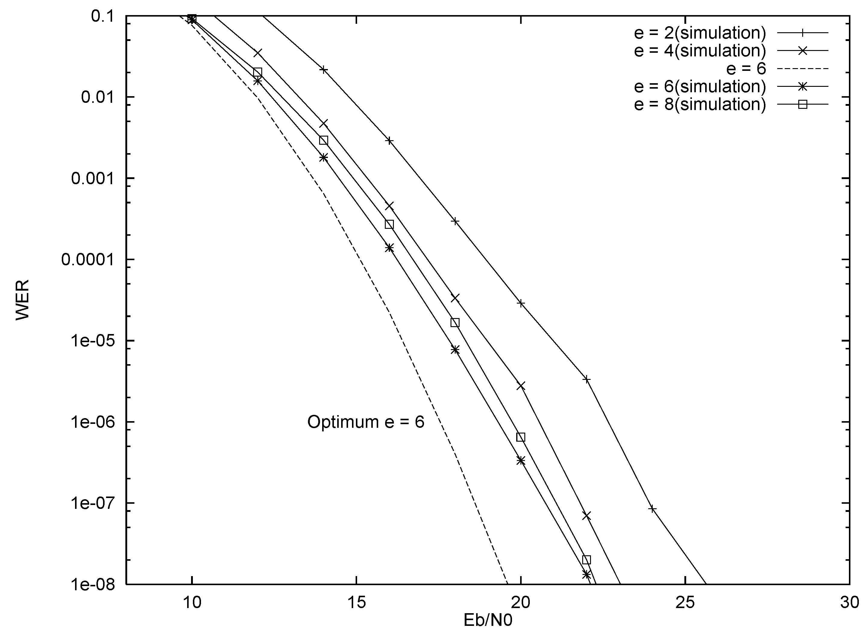
4.1. Erasure Generation by Ordering Fading Amplitudes
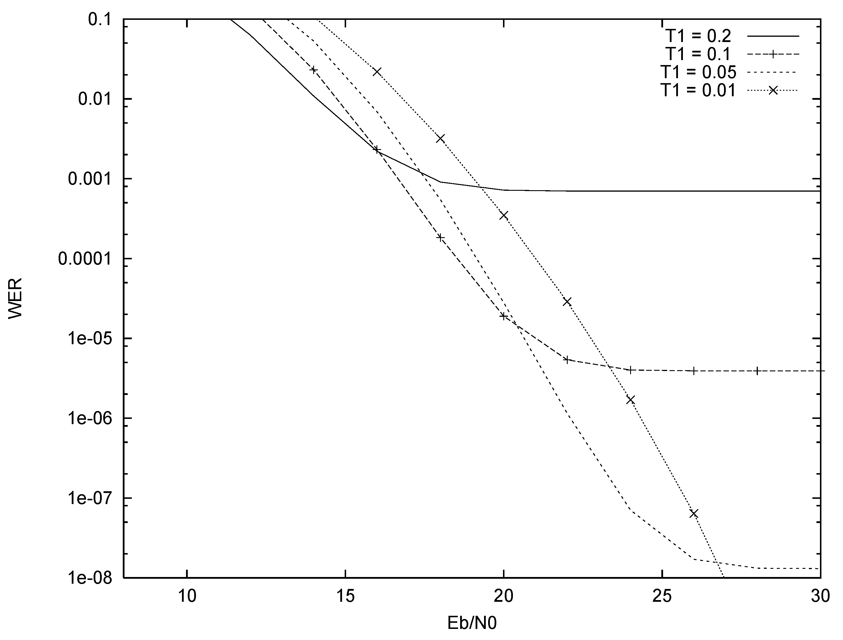
4.2. Erasure Generation by Comparing Fading Amplitudes with a Threshold
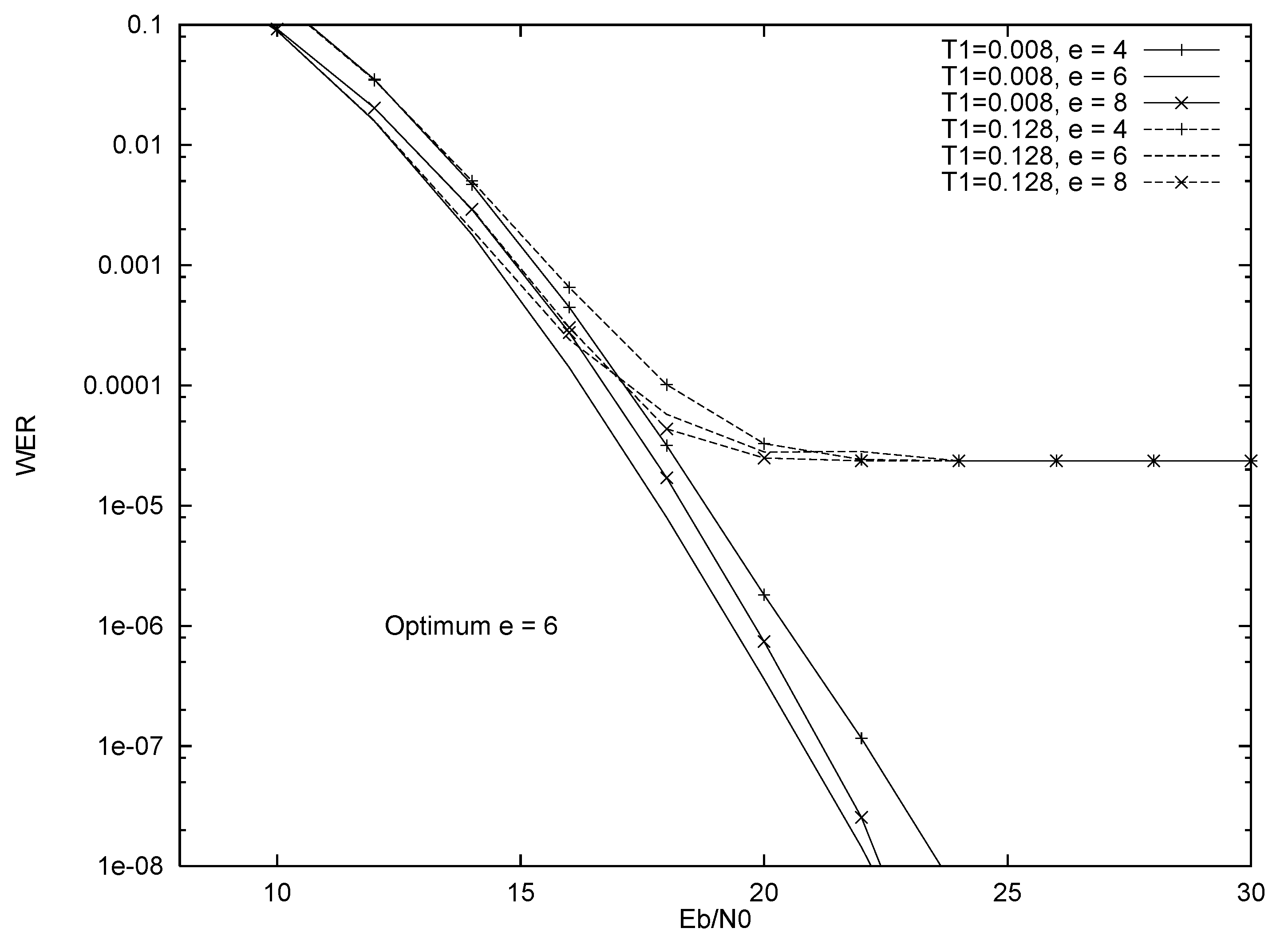
4.3. Erasure Generation by Ordering and Comparing Fading Amplitudes with a Threshold
5. Results
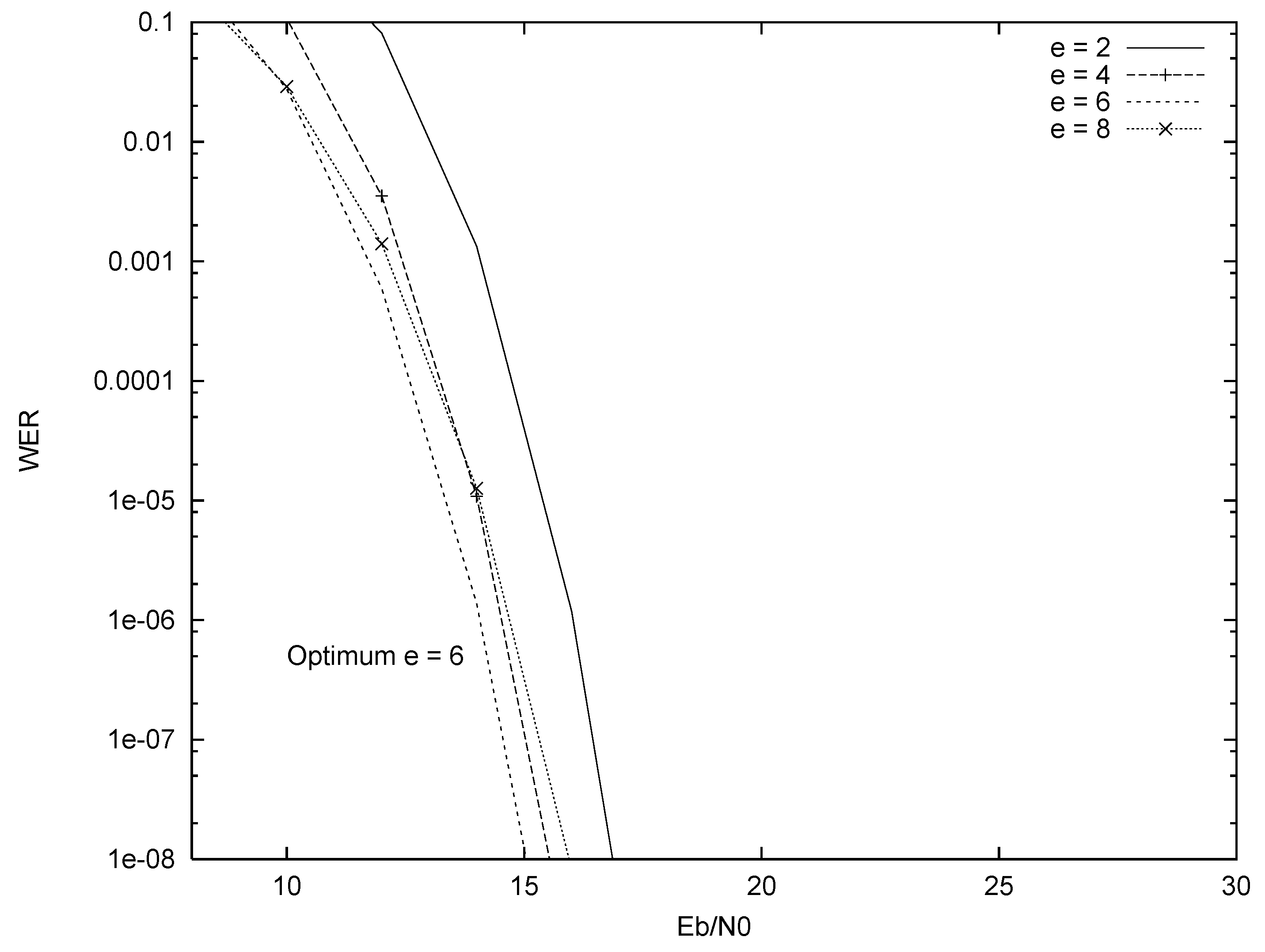
5.1. Truncated Channel Inversion
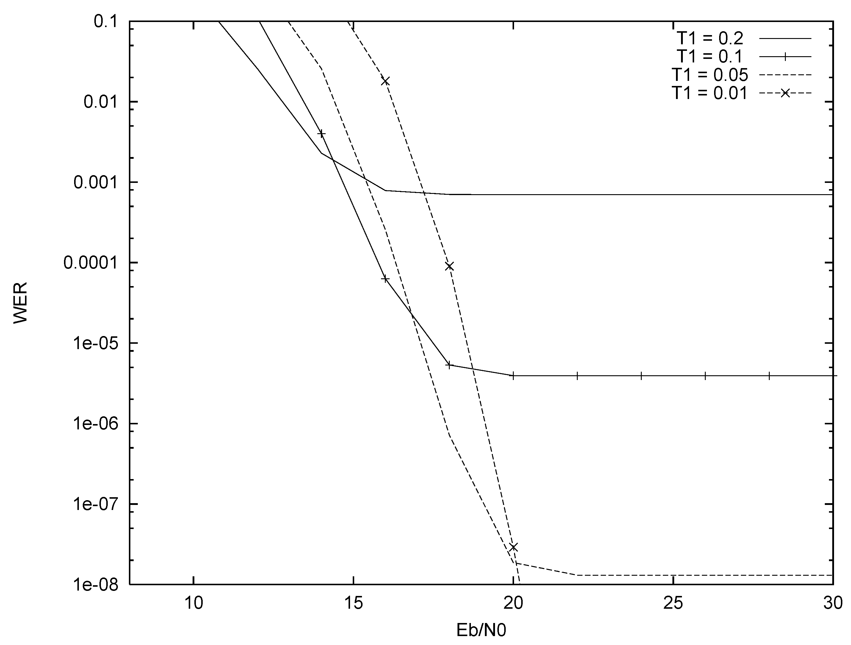
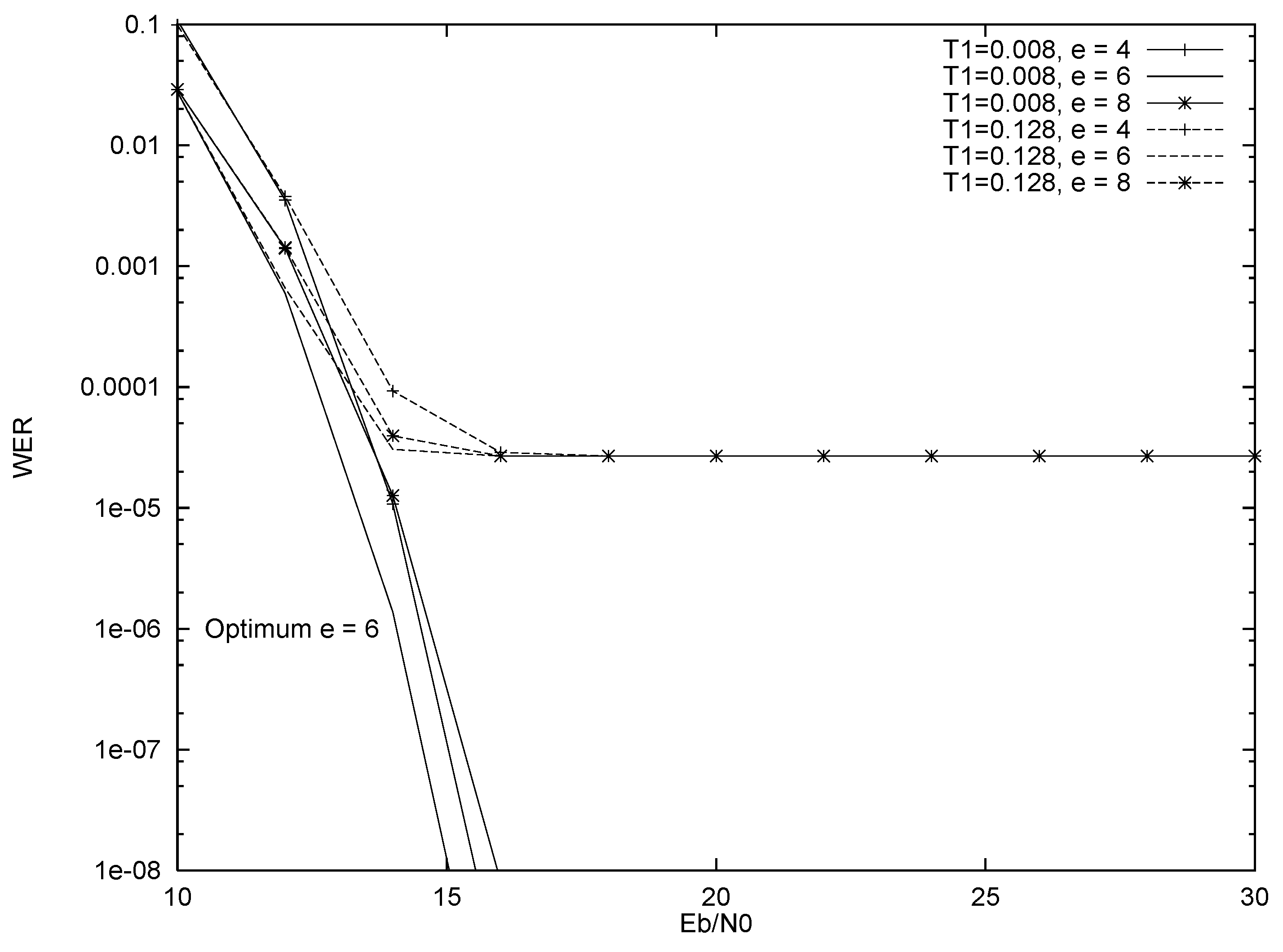
5.2. Truncation Only
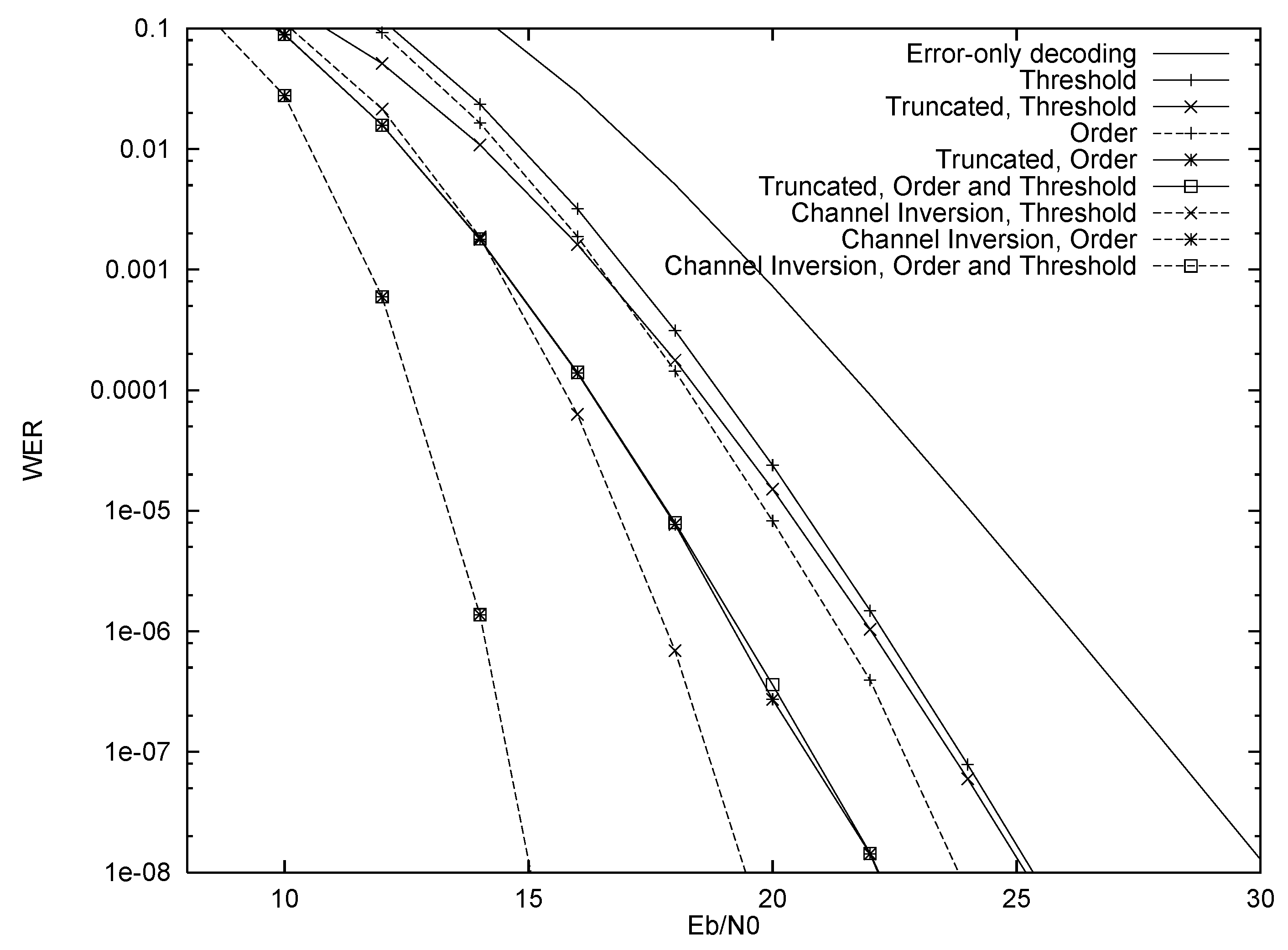
5.3. Performance Comparison of Systems
6. Conclusions
Funding
Institutional Review Board Statement
Informed Consent Statement
Data Availability Statement
Conflicts of Interest
Appendix A. Proof of the Fact that Ordering Does Not Preserve Independence
Appendix B. Derivation of (5) and (19)
Appendix B.1. Derivation of (5)
Appendix B.2. Derivation of (19)
Appendix C. Verification of (19) and (20)
Appendix C.1. Verification of (19)
Appendix C.2. Verification of (20)
References
- Fossorier, M.P.C.; Lin, S. Soft decision decoding of linear block codes based on ordered statistics for the Rayleigh fading channel with coherent detection. IEEE Trans. Commun. 1997, 45, 12–14. [Google Scholar] [CrossRef]
- Hayes, J.F. Adaptive feedback communications. IEEE Trans. Commun. 1968, 16, 29–34. [Google Scholar] [CrossRef]
- Goldsmith, A.J.; Chua, S.G. Variable-rate variable-power MQAM for fading channels. IEEE Trans. Commun. 1997, 45, 1218–1230. [Google Scholar] [CrossRef]
- Simpson, F.; Holzman, J.M. Direct sequence CDMA power control, interleaving, and coding. IEEE J. Select. Areas Commun. 1993, 11, 1085–1095. [Google Scholar] [CrossRef]
- Matsumoto, T.; Higashi, A. Performance analysis of RS-coded M-ary FSK for frequency-hopping spread spectrum mobile radios. IEEE Trans. Veh. Technol. 1992, 41, 266–270. [Google Scholar] [CrossRef]
- Hagenauer, J.; Lutz, E. Forward error correction coding for fading compensation in mobile satelite channels. IEEE J. Select. Areas Commun. 1987, 5, 215–225. [Google Scholar] [CrossRef]
- Hara, S.; Prasad, R. Overview of multicarrier CDMA. IEEE Commun. Mag. 1997, 35, 126–133. [Google Scholar] [CrossRef]
- Lin, S.; Costello, D.J., Jr. Error Control Coding: Fundamentals and Applications; Prentice-Hall: Hoboken, NJ, USA, 1983. [Google Scholar]
- Kim, S.W.; Goldsmith, A. Truncated power control in code division multiple access communications. IEEE Trans. Veh. Technol. 2000, 49, 965–972. [Google Scholar] [CrossRef]
- Proakis, J.G. Digital Communications; McGraw-Hill: New York, NY, USA, 1995; p. 280. [Google Scholar]
- Lakshmi, M.V.; Reddy G., G.; Sucharitha, A.; Akshara, N.; Vaishnavi, N. Performance comparison of channel coding techniques for OFDM system. IOP Conf. Ser. Mater. Sci. Eng. 2022, 1272, 012012. [Google Scholar] [CrossRef]
- Gradshteyn, I.S.; Ryzhik, I.M. Table of Integrals, Series and Products; Academic Press: Oxford, UK, 1980; p. 326. [Google Scholar]


| WER = | WER = | |
|---|---|---|
| Error-only decoding [1] | 20 | 26 |
| Threshold [6] | 17 | 22 |
| Truncated, Threshold [9] | 15.8 | 21.8 |
| Order [5] | 16 | 21 |
| Truncated, Order | 14.5 | 19.5 |
| Truncated, Order, and Threshold | 14.5 | 19.5 |
| Channel inversion, Threshold | 14.3 | 17.5 |
| Channel inversion, Order | 12 | 14 |
| Channel inversion, Order, and Threshold | 12 | 14 |
| Coded OFDM Scheme | Gain over Uncoded OFDM Scheme |
|---|---|
| Convolutional-coded OFDM | 2 dB |
| RS-coded OFDM | 3.5 dB |
| RS-coded OFDM with truncated channel inversion | 7 dB |
Disclaimer/Publisher’s Note: The statements, opinions and data contained in all publications are solely those of the individual author(s) and contributor(s) and not of MDPI and/or the editor(s). MDPI and/or the editor(s) disclaim responsibility for any injury to people or property resulting from any ideas, methods, instructions or products referred to in the content. |
© 2023 by the author. Licensee MDPI, Basel, Switzerland. This article is an open access article distributed under the terms and conditions of the Creative Commons Attribution (CC BY) license (https://creativecommons.org/licenses/by/4.0/).
Share and Cite
Kim, Y. Power Control of Reed–Solomon-Coded OFDM Systems in Rayleigh Fading Channels. Information 2023, 14, 247. https://doi.org/10.3390/info14040247
Kim Y. Power Control of Reed–Solomon-Coded OFDM Systems in Rayleigh Fading Channels. Information. 2023; 14(4):247. https://doi.org/10.3390/info14040247
Chicago/Turabian StyleKim, Younggil. 2023. "Power Control of Reed–Solomon-Coded OFDM Systems in Rayleigh Fading Channels" Information 14, no. 4: 247. https://doi.org/10.3390/info14040247
APA StyleKim, Y. (2023). Power Control of Reed–Solomon-Coded OFDM Systems in Rayleigh Fading Channels. Information, 14(4), 247. https://doi.org/10.3390/info14040247