Abstract
In embedded electronic system applications being developed today, complex datasets are required to be obtained, processed, and communicated. These can be from various sources such as environmental sensors, still image cameras, and video cameras. Once obtained and stored in electronic memory, the data is accessed and processed using suitable mathematical algorithms. How the data are stored, accessed, processed, and communicated will impact on the cost to process the data. Such algorithms are traditionally implemented in software programs that run on a suitable processor. However, different approaches can be considered to create the digital system architecture that would consist of the memory, processing, and communications operations. When considering the mathematics at the centre of the design making processes, this leads to system architectures that can be optimized for the required algorithm or algorithms to realize. Mathematics of Arrays (MoA) is a class of operations that supports n-dimensional array computations using array shapes and indexing of values held within the array. In this article, the concept of MoA is considered for realization in software and hardware using Field Programmable Gate Array (FPGA) and Application Specific Integrated Circuit (ASIC) technologies. The realization of MoA algorithms will be developed along with the design choices that would be required to map a MoA algorithm to hardware, software or hardware-software co-designs.
1. Introduction
Embedded electronic system applications commonly realized today are required to process large amounts of data in order to undertake value-added operations such as embedded Machine Learning (ML) [1] and Deep Learning (DL) [2] that allow the system and hence the user to make sense of the available provided data. Complex datasets are required to be obtained, processed, and communicated. These can be from various sources such as environmental sensors, still image cameras, and video cameras. The suitably formatted data are available in memory and conceptually arranged into multi-dimensional arrays. Once obtained and stored in electronic memory, the data are accessed and processed using suitable mathematical algorithms. How the data are stored, accessed, processed, and communicated will impact on the cost to process the data. Such algorithms are traditionally implemented in software programs that run on a suitable processor. Standard electronic system architectures utilize off-the-shelf processors such as the Central Processing Unit (CPU) [3] and Graphics Processing Unit (GPU) [4]. Recently, the processor selection option has been augmented by the Tensor Processing Unit (TPU) [5]. The processor architecture, access to suitable memory, and the available communications will impact the design efficiency. This design efficiency will lead to a cost associated with the different parts of the software and hardware such as required processing time and the electronic system power consumption, considering both static and dynamic power.
Extending the standard architecture approaches where off-the-shelf devices are obtained and the different Integrated Circuits (ICs) that will be connected together to implement specific system requirements leads to custom designs utilizing the Field Programmable Gate Array (FPGA) [6] and the Application Specific Integrated Circuit (ASIC) [7]. Such approaches allow for custom digital system architectures to be designed, developed, and deployed to best suit the requirements of a particular application. This allows for the algorithms to be implemented in software, hardware, or as hardware-software co-designs where the implementation approach would be selected for the application or range of applications.
Different approaches can be considered to create the digital system architecture that would consist of the memory, processing, and communications operations. Considering the mathematics at the centre of the design making processes leads to system architectures that can be optimized for the required algorithm or algorithms to realize. Mathematics of Arrays (MoA) [8] is a class of operations that supports n-dimensional array computations using array shapes and indexing of values held within the array. This, for example, includes the ability to support tensor inner and outer products. With this, a tensor is considered an n-dimensional array that can be processed using summation/subtraction and multiplication/division operations. When considering multiplication of arrays, different products such as the tensor inner and outer products as well as vector and matrix multiplications are possible, and a combination of these, and other, operations would be required.
In this article, the concept of MoA is considered for realization in software and hardware using FPGA and ASIC technologies. The realization of MoA algorithms will be presented along with design choices that would be required to map a MoA algorithm to hardware, software or hardware-software co-designs. With reference to a developed algorithm before and after MoA optimization, the implementation of the algorithm in software (using Python [9] and C [10]) and hardware (using the Verilog Hardware Description Language (HDL) [11]) will be presented. The hardware and C-language software versions of the algorithm will then be presented for an implementation within a Xilinx Artix-7 FPGA [12]. The overall concept to develop is shown in Figure 1. This concept will be elaborated in the article and is used for development and evaluation purposes.
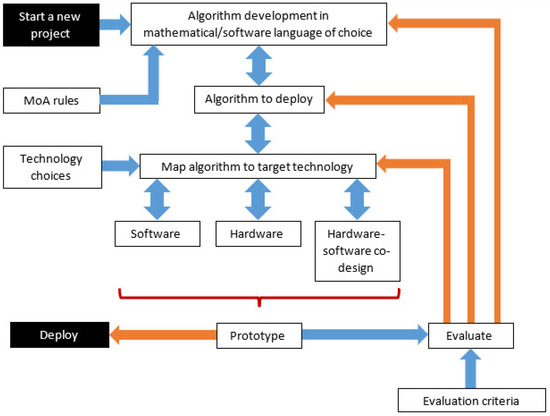
Figure 1.
Concept to develop.
MoA is used for a number of very important theoretical and practical reasons relevant to Portable, Performant, and Productive Parallel Programming, often referred to as the P3 problem, formulated by M. Wolfe [13]. MoA is proposed as a solution. First, all of Tensor Algebra in libraries such as NumPy and Linpack can be formulated in MoA, and thus can be reduced through Psi Reduction (composition of indexing operations based on MoA’s Psi indexing function and shapes), to a semantic (Denotational), Normal Form (DNF) that reveals the minimum amount of computation to be performed where all parallelism is revealed. Thus, all AI applications utilizing languages and libraries, such as NumPy, Julia, and MATLAB, can be further optimized, noting that MoA’s matrix multiplication outperforms standard DGEMM libraries [14,15]. Next, as MoA views the data, and all machine components as arrays with shapes, indexing of data can easily be mapped to indices of architectural components: processors, memories, interconnects, where cost functions can be calculated deterministically. Finally, the potential exists to remove all decisions from the user, thus guaranteeing Productivity while insuring high Performance and Portability.
The article is structured as follows. Section 2 will provide an overview of MoA, its principles, and application in the context of the work presented. How an algorithm consisting of array products can be optimized with a mapping to contiguous memory will be presented. Section 3 will discuss the design of digital systems using FPGA and ASIC technologies. This will identify the different approaches that can be taken to take a concept through to physical realization with reference to MoA requirements. In this article, the FPGA will be utilized as this type of electronic device that supports rapid prototyping and cost-effective design modification. Section 4 will present the mapping of MoA algorithms to both software and hardware realizations, as personal computer (PC) based software programs/scripts and as both hardware and software realizations within the FPGA. Design choices and implications of such choices will be considered. Section 5 will present a case study algorithm development and deployment within a Xilinx Artix-7 FPGA. The initial algorithm consisting of array product and accumulation operations will be developed in Python and NumPy [16]. MoA optimization of this algorithm will be undertaken, breaking down the products into nested for loops, and the optimized algorithm will be verified in both Python/NumPy script and C program implementations. To demonstrate the principles, a small dataset modelled as two 2 × 2. matrices will be considered. In general, the datasets would be larger, however for demonstrating the principles then the size of the dataset was deliberately limited. With larger datasets, the algorithm would not change but the processing time and data storage memory requirements would increase. The optimized algorithm will then be mapped to a software implementation based on an embedded Xilinx MicroBlase Reduced Instruction Set (RISC) microprocessor [17] and a hardware implementation based on a synthesized Verilog HDL design description. The design process and implementation results will be presented. Finally, Section 6 will conclude the article.
2. Mathematics of Arrays Principles and Application
A goal of MoA research is to algebraically specify a problem, in whatever semantically equivalent syntax, and mechanically transform that specification to optimal computational platforms by mapping indices of data to indices of architectural components, e.g., registers, processors, and memory [18,19]. MoA is a mathematical theory, not a programming language. It is like Calculus where formulations are made and derived by hand with automation learning from such designs. Numerous formulations of important algorithms have been mechanically transformed by hand, for example QR, LU, FFT, KP, and KR, through compositions of indexing operations, referred to as Psi Reduction. Automated platforms are currently under development [20] to map indices of data to indices of architectural components while incorporating cost functions [21,22,23,24].
2.1. Why a New Theory of Arrays?
Any reader preferring an overview of this subject is encouraged to just read the italicized sentences at the end of this sub-section. Linear, and Multilinear Algebra, Matrix Operations, Decompositions, and Transforms dominate the IoT (Internet of Things), AI (Artificial Intelligence), ML (Machine Learning), and Signal Processing applications. In particular, General Matrix Matrix Multiplication (GEMM) [14,15] and the Kronecker Product (KP) are the most common [25] products. The Khatri-Rao (KR), i.e., parallel KPs, was reported to subsume 90% of all IoT computation at Siemens in Munich [26]. In AI, Recurrent Neural Networks (RNNs) can be difficult to deploy on resource constrained devices. KPs can compress layers by 16 - 38 times with minimal accuracy loss [27]. Both, MM and KP occur often and in multiples [28] within today’s software AI tools, e.g., Tensorflow and Pytorch, written in Python and NumPy. Due to the use of interpretive languages that are utilized to formulate these tools, even with NumPy, and other software accelerators to speed up interpretation, special purpose hardware is being explored, e.g., GPUs and TPUs, as an assist (co-processing). Even with all this, the necessary speeds and sizes of matrix operations needed are not being realized.
In MoA, the theoretical foundations start with shapes and the Psi indexing function. Together they can define arbitrary array operations that, when composed, yield a semantic/Denotational Normal Form (DNF), or least amount of computation, and memory access, needed for the algorithm while revealing all parallelism. From the DNF, loops bounds are partitioned, "dimension-lifted", to map to the hardware. MoA views the hardware as arrays: indices of data to indices of machine attributes (registers, memories, processors), combined with costs [8,29,30,31]. MoA is Turing Complete, and has the Church-Rosser (CR) property [32], and when combined with the Lambda Calculus [33], two array programs can be proven equivalent.
Existing array theories and compiler optimizations on array loops, are proper subsets of MoA. All of NumPy’s array and tensor operations can be formulated in MoA. In MoA one algorithm, thus, one circuit, describes the Hadamard Product, Matrix Product, Kronecker Product, and Reductions(Contractions) versus four. Consequently less circuitry, power, and energy.
2.2. The Simplicity of MoA: Shapes and the Psi Function
Although MoA’s algebra was influenced by Iverson’s APL [34] and Abram’s shapes and indexing tables [35], it is MoA’s Psi Function, , with shapes that defines everything. Any mathematical quality: group, ring, field,..., could be added to MoA’s indexing calculus. The idea of MoA and Psi Calculus, starts with a scalar, , and it’s shape , an empty vector, denoted by or . Since a vector is an array, it has a shape, , the one element vector containing the integer 0, denoting a scalar is a 0-dimensional array. Thus, from the shape, we can determine dimensionality, and the total number of components, , in the array. Algorithms on shapes describe how to index arrays with Psi and are defined, such that, Psi takes a valid index vector, or an array of valid index vectors, and an array as arguments. For example, in the scalar, , case, . Next, 2 scalars(0-d) and operations between them can be considered, with an extension to operations with n-dimensional (n-d) arguments.
Scalar operations are at the heart of computation, , and in general for n-d arrays, , where f is an arbitrary scalar function.
Thus, in general,
That is, indexing distributes over scalar operations, or in compiler optimization terms, loop fusion.
For a scalar there is only one valid index, is , the empty vector.
Indexing distributes over scalar operations.
Relating the DNF to the Operational Normal Form (ONF). rav flattens the array in row major. gets the offset using index and shape.
Applying the definition of in order to get 0.
Bracket Notation relates to the ONF, or how to build the code, through and pseudo-code, i.e., . With a family of gamma, , functions, e.g., row major, column major, a Cartesian index is related to an offset of the array in memory laid out contiguously. rav flattens an array based on it’s layout. Subscripts relate to left or right arguments and superscripts specify dimensionality. Refer to [8] for all MoA definitions.
With this, introduce the important identify that is true in general for n-d arrays, denoted by :
This means, with an array’s shape, , generate an array of indices, . Then, using that array as an argument to Psi, the original array ξ, is returned.
In the scalar case, where denotes a scalar,
The shape of a scalar is the empty vector and, and the only valid index a scalar has is the empty vector, .
Thus, as long as we can get shapes, e.g., , we can get all indices from shapes, e.g., that have the properties of the function. This is true in general, no mater what the dimensionality of the array [8], including scalars, a 0-dimensional array.
Building upon scalar operations, and extending to scalar vector operations, introduced as scalar extension, later generalized as the outer product. The generalization is completed by adding reductions/contractions and, the inner product (defined using reduction and outer product). Mullin’s research connects these four ideas formulated mathematically in MoA; scalar operations: Matrix Multiplication (MM), Hadamard Product (HP), and the Kronecker Product (KP) using one algorithm/circuit (ipophp) [36,37]. These designs were extended to Blocked matrix matrix multiplication by first formulating in MoA, then derived, built, and tested in C, proving it’s performance exceeds modern DGEMM libraries [14,15]. From these experiments, it became clear that a general purpose machine, e.g., cache memory design, languages, Operating Systems (OSes), compilers,..., would not suffice for optimal array computation. Memory management, resource management, and the ability to control and optimize array computation was difficult if not impossible. Much information about the machines was either inaccurate, or was not divulged. Consequently, guided experiments with sophisticated scripts that overlay performance plots, helps to obtain essential, unknown variables in a developing theoretical MoA model of computation. This information guides the research herein. Research continues to validate that the more shape aware the Operational Normal Form (ONF) is of data and hardware, the easier it is to use special purpose hardware to obtain large amounts/blocks of data(strided DMAs and RMAs, buffers, PIMs,...), that could easily use pre-scheduled information of sizes and speeds, up and down the memory hierarchy, deterministically.
MoA defines all operations using shapes and the Psi indexing function. Hence, when operations are formulated in the MoA algebra, they can be reduced through Psi Reduction to a semantic/denotational normal form (DNF), i.e., Cartesian indices of all operations are composed. Then, one of the mapping functions, e.g., . There are a whole family of , layout functions, e.g., , that transform an index to an offset in memory, the ONF, or how to build it with knowledge of data layout that capitalizes on starts. stops. and strides [38]. Next, formulating dimension lifting, i.e., partitioning shapes, leads to mapping data to hardware [30]. Combined with Lambda Calculus, iteration, sequence, and control [33], we have a Turing complete paradigm to reason about array computation in general. These fundamentals allow one to define and optimize programs in any domain that use the algebra and could be enhanced subsets of any language with arrays, e.g., Fortran, Python, or Julia [21]. That is, when there is semantic equivalence across programming languages, soft or hard, automatic linear and multi-linear transformations are easily applied, proving correctness by construction. MoA is a Universal Algebra than can optimize all domain specific languages that use arrays/tensors as their primary data structure.
2.3. Why MoA Inner and Outer Products?
Tensor contractions are 3-d extensions of the matrix multiplication [39]. Thus, optimizations for higher dimensional contractions using plus and times (addition and multiplication) are also needed. In MoA, the formulation of the inner uses the outer product, noting the degenerate form of the outer product, is scalar operations. When this is combined with reduction/contraction, i.e., reducing a dimension through addition, or other scalar operation, we have higher dimensional HP, KP, and MMs in one algorithm/circuit (ipophp) or many parallel 2-d versions. An example will help in understanding these concepts.
2.4. Examples: MM, KP and, HP
In order to explain why the MoA design and implementation outperforms classical designs, and why MoA is a model of array computation, consider an example with two 3 by 3 matrices and look at the memory access patterns for the Kronecker and Matrix Products, initially performed classically and then in MoA. This can then be extrapolated to 3-d and above. Higher-dimensional SVDs and FFTs, use the KP. When investigating MoA optimizations of these algorithms, or multiple uses of these algorithms, it is not the arithmetic complexity that changes, it is the IO complexity and contiguous memory access, combined with regular memory access patterns, governed by shapes, that yields a higher performance. Once the ONF is obtained, dimension lifting is applied. That is, shapes are partitioned, and when combined with memory access patterns, that are related to the memory hierarchy, it becomes possible to calculate and provide apriori knowledge to hardware, e.g., prefetchers, DMAs, RMAs,..., memories, or any special purpose hardware or memories amenable to regularly strided, memory access patterns.
Notice that in Figure 2, the classical KP of 2-d matrices yields a larger 2-d matrix and necessitates multiple long strides to place each block in the new larger array. The amount of space changes in the same way for both algorithms but in MoA 2, 2-d arrays using an outer product would yield a 4-d array, with all array accesses contiguous. In the case of Figure 2 the matrix becomes a 9 by 9, and in MoA, a 3 by 3 by 3 by 3, that gets transposed and reshaped to 2-d. This concept is extremely important with multiple KPs [28] when only one transpose is used after many multiple contiguous operations and is used with reshape, to permute the indices into their final strided matrix locations. Additionally, notice scalars from the left argument are used with all of the right argument, an outer product, also called scalar-extension.
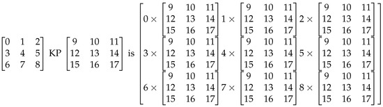
Figure 2.
Kronecker Product.
Now considering the MM as shown in Figure 3. It too has large strides to perform the classical row/column operations and gets more complicated as the MMs become 3-d tensor contractions. If done using MoA, only accumulating scalar vector operations are performed. The only thing different form KP, is the accumulation. For n-d, everything remains the same, and scalar vector operations are performed. In Figure 3, for MoA, the entire 0th row of the result is obtained by the summation of the following products (0,0)th component of the left argument times the 0th row of the right argument, (0,1)th component of the left argument times the 1st row of the right argument, (0,2)th component of the left argument times the 2nd row of the right argument.

Figure 3.
Matrix Multiplication.
So, for both MM and KP, all array access is contiguous. MM uses KP creating one algorithm that subsumes scalar, vector and tensor operations on today’s GPUs and is the basis for this case study to investigate building an MoA OS and Machine.
This case study will investigate how shapes affect design and size of memories relative to computational units. MoA will be used to explore how relationships of algorithms and memory access patterns help to optimize algorithms across many domains that use tensors and arrays. These studies will yield information to move forward with an MoA OS that manages and optimizes all memory and computational resources, starting with memory management.
General Algorithms: Kronecker: FFT and Wavelets
When more relationships can be found between algorithms, optimizations can be made in software and hardware, e.g., the KP is used to define the FFT, the Haar Wavelet is a subset of the FFT’s memory access patterns, and PDE solvers are related to FFT’s access patterns. Identifying relationships enable the designer to develop a single circuit thus enabling less circuitry, less power, and less energy. Once patterns are found, starts, stops and strides can be assigned dynamically within the hardware similar to the combined MM, KP, HP circuit developed by the authors.
3. Digital Systems Design Using Field Programmable Gate Array and Application Specific Integrated Circuit Technologies
Within electronic systems derived and utilized today, it is typical for the core functions of the system to be implemented using digital logic circuits supported with various types of memory for data and program storage. There are multiple approaches that can be adopted to realize a working solution. Considering the implementation approaches, the typical approaches considered are:
- 1.
- Software programmed processor. A standard processor architecture based on the CPU, GPU or TPU would be used (or created as a custom architecture processor) with the aim to run a suitable software program. This could target a PC application or an embedded (system) application. The selection of the processor and overall system would need to be based on the target application, whether it is aimed at general-purpose or application-specific needs. The ability to initially program and then re-program the system operation multiple times by changing the software program would be an integral part of the system functionality. Typically, C and C++ programs are created. Whilst predefined processor architectures may be suitable for many applications, it may be necessary to consider modifying an available processor architecture to improve performance. For example, in ref. [40], ten reasons for optimizing a processor are presented.
- 2.
- Field Programmable Gate Array (FPGA). The FPGA is a programmable device that consists of programmable hardware and programmable interconnect. This allows a digital system design to be developed and programmed (configured) into memory within the FPGA that controls the programmable parts of the device. Devices available today allow for designs to be created as hardware only designs or hardware-software co-designs where one or more processors can be embedded into the device. Typically, Verilog HDL and VHDL (VHSIC (Very High Speed Integrated Circuit) HDL) are used to describe the hardware (logic and memory), and C and C++ programs are created to run on the embedded processor(s). This allows for low-cost entry into digital system design and fast design prototyping as well as for creating the final system where applicable.
- 3.
- Application Specific Integrated Circuit (ASIC). Here, the designer creates an IC design to implement the required circuits functions. This allows for the most efficient design to be created (circuitry used, performance and power consumption), but would be a high cost approach where low volumes are produced. However, the ASIC approach becomes cost effective when high volume production is considered. Typically, Verilog HDL and VHDL are used to describe the digital hardware (logic and memory). Either one HDL only or both HDLs may be utilized in a design project for describing both the design modules and simulation testfixture modules.
These different approaches have developed over the years and there are a wide range of possible solutions for a software based approach. Here, the developer will create the software program that targets a standard, and in many cases fixed, hardware platform. Hence, the main effort is in the development of the software. This has many advantages, particularly for design time and software design efficiency. Increasingly, a hardware based alternative to implementing functions considered in software is becoming attractive to reduce the time to implement functions when compared to software. This can give a higher data-throughput, particularly important to systems requiring complex and high-speed computations in a real-time application. For example, AI, ML, and DL applications require multiple addition/subtraction and multiplication/division operations on large multi-dimensional arrays. FPGA and ASIC technologies provide the opportunity to implement such hardware functions and also to develop custom architectures that are better suited to computations on large multi-dimensional arrays. However, the design approaches to be adopted in such cases require the designer to think in terms of hardware operation rather than software behavior, and to have a greater understanding of design decisions on the operation of the underlying hardware platform.
4. Mapping MoA Algorithms to Software and Hardware
Mapping of the MoA algorithm takes the abstract algorithm description into a suitable description within a suitable software programming (or scripting) language or HDL. Therefore, once the MoA algorithm has been defined, it can be implemented in software running on a suitable processor, hardware using defined digital logic and memory circuits, or a mixture of both software and hardware functions. Following a suitable design approach would lead to the ability for identifiable and repeatable results to be obtained, particularly important for design verification. Figure 1 shows the approach to follow from initial concept to deployed implementation. This figure shows the key steps and verification steps to be followed.
Considering the tasks to perform to be undertaken within a project, and with reference to Figure 1, starting with a new project then the tensor products to optimize are defined and MoA optimization performed (Algorithm development in mathematical/software language of choice) using a set of MoA rules. Here, optimization refers to the transformation of the original tensor products into operations contained within nested for-loops accessing data within multi-dimensional arrays that are realized as data stored in contiguous memory. The Algorithm to deploy is identified and its behavior verified to ensure the pre- and post-optimization behaviors are equivalent (in terms of the array data and data transformation). With this algorithm in a suitable format, it is then targeted to an appropriate realization (Map algorithm to target technology); an implementation in Software, Hardware or as a Hardware-software co-design design. The choice as to the implementation would depend on a number of factors such as the available technologies, designer experience, and specific design requirements (Technology choices). Once defined and the necessary design descriptions created, the system would initially be built as a Prototype. This prototype system would need to be tested (Evaluate) against a set of requirements (Evaluation criterion). With the need to refine the system operation, feedback loops to different stages in the design creation process would be supported before the prototype could be completed and the final system released (Deploy).
When considering the selection of software or hardware, this task requires careful thought to achieve the desired results. Considering a different way to view Figure 1, MoA optimization and technology mapping can be viewed as shown in Figure 4. This is the approach adopted in this work to take the MoA optimized algorithm to a realized implementation.
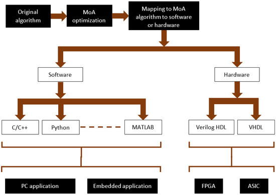
Figure 4.
MoA optimization and technology mapping.
Here, the specific subset of possible ways to describe a software or hardware implementation is shown. Specifically here, software descriptions are considered in C/C++, Python, and MATLAB, whereas hardware implementations are considered as Verilog HDL or VHDL design modules. The software would aim to run on a suitable processor, either a PC application or an embedded application. The hardware would be targeting specific digital circuits to be implemented within an ASIC or FPGA.
5. Case Study Design
In this section, an example algorithm developed using Python and NumPy is mapped to C-code, MATLAB, and Verilog HDL. Two C-code versions have been developed: the first for compiling to an executable file to run on a PC whilst the second targets an embedded application using an implementation of the Xilinx MicroBlaze microprocessor within the Xilinx Artix-7 FPGA. However, given that the code here is standard C, the same code describing the algorithm can be placed within a function and used in both versions (PC application and embedded MicroBlaze). The Verilog HDL version was initially developed for behavioral modelling and simulation using the for-loop implementation, and then remodelled for synthesis and implementation by using hardware counter and state machine circuits supporting the same functionality as the for-loop version.
Consider the following Python code, where the output array z is created by a combination of tensor products using NumPy functions on input arrays a and b, as shown in Figure 5:
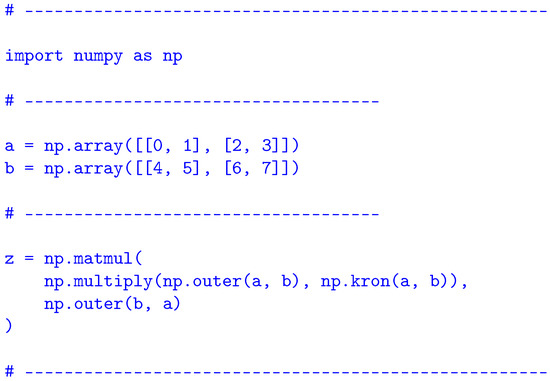
Figure 5.
Case study example algorithm in Python and NumPy.
- Matrix multiplication (np.matmul).
- Element-by-element multiplication, the Hadamard Product (np.multiply).
- Tensor Outer Product (np.outer).
- Kronecker Product (np.kron).
5.1. Python with NumPy
This algorithm, along with example input array values, defined in NumPy (Figure 5) demonstrates a set of the typical tensor products used in ML and AI applications:
5.2. MoA Definitions
Once NumPy definitions are defined in MoA, they can be Psi Reduced to a DNF and ONF followed by a generic program. The 2 by 2 arrays, a and b above are used in the following definitions:
- NumPy’s definition of Hadamard Product, np.multiply, is simply MoA’s definition of scalar operations on n-d arrays, e.g., product. In MoA:
- NumPy’s definition of outer product, np.outer is defined in MoA as follows and is simply a reshaping of MoA’s shape to NumPy’s, in this case to :
- NumPy’s definition of the Kronecker Product, np.kron, is the same as MoA. However, like the matrix multiplication, accesses all arrays contiguously, then at the end permutes them to their reshaped locations. This is particularly important with multiple Kronecker Products [28].
5.3. Small Example of Psi Reduction to DNF, ONF, and Generic Program
The derivation of the Python program is too long to present within this article. Thus, a small example will be presented to demonstrate the process. If the reader desires a derivation that combines both the Psi and Lambda Calculus, the Conjugate Gradient is an good example, and a reference to this can be found at https://arxiv.org/pdf/1904.02612.pdf. Although the example that follows is very elementary it illustrates the process of Psi Reduction to DNF, ONF and Generic Program. Using the arrays a, b, and definition for the Hadamard Product above, np.multiply.
Reduce:
- (1)
- Psi Reduce to DNF:
- (a)
- Get the Shape:By definition, shapes must be conformable. So the shape of must be equivalent to the shape of b and the shapes of a and b must be the same.
- (b)
- Get the Components: Here the Psi function is used because layout of the arrays does not matter. Psi Reduction is applied based on the definitions to compose the indices to it’s DNF, or semantic normal form, the least amount of computation AND memory needed to perform the operations. With the shape we have the bounds of indices i and j:Now use the Psi function to Psi Reduce to the DNF:In order to turn the DNF to ONF, layout of the arrays in memory is needed. Assume a and b are layout in row major order. A family of gamma functions, i.e., layout functions that map indices to their offset in memory exist. For this example is used. Gamma takes an index and a shape.
- (2)
- Get the ONF:rav is a function that flattens an array based on layout. Bracket notation is now used to illustrate the building phase of design:This is the ONF.
- (3)
- Generic Program:Finally, using standard notation for the generic program letting C to denote the result, and A and B to denote a and b.This is the Generic Program and illustrates the process of going from a high level mathematical specification in NumPy formulated in MoA, Psi Reduced to the DNF, ONF and finally to a generic program.
5.4. Returning to the Python Example
The algorithm identifies the products to implement and the order of implementation, but as is common in high-level programming, the hardware implementation is hidden from the programmer and so the programmer does not immediately know the computation time and memory requirements in order to solve the problem. This however can be visualized as shown in Figure 6. Here, the algorithm and data flow are depicted using a block diagram, but this simple view does not identify data characteristics such as array shapes, array dimensions, data numeric range, and data types. The block diagram supports an understanding of the data flow and data transformations, but hides details that would be required for a correct implementation in software or hardware.
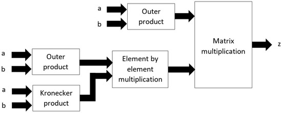
Figure 6.
Visualization of the algorithm in Python and NumPy.
Optimizing this algorithm (Figure 5) using MoA allows the same functionality to be achieved using for-loops and data stored and accessed in contiguous memory that can then be mapped to different software programming and hardware description languages. In the example, matrices (two-dimensional arrays) are considered and these are modelled as one-dimensional arrays stored in memory. Mapping the optimized algorithm to C-code then gives five for-loops and a two-dimensional output array as shown in Figure 7. However, the ability for HDL synthesis tools to synthesize multi-dimensional arrays and to map to appropriate hardware resources requires careful consideration.
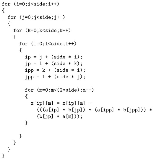
Figure 7.
Algorithm in C.
In MATLAB, see Figure 8, the code is similar to the C-code version, but now considering the indexing approach where the first element of an array in C is index 0 whereas in MATLAB it is index 1. Hence, a small modification to the for-loops and algorithm was required for correct array indexing each time through each loop. This code was developed to provide an additional way in which to implement the algorithm, but pre- and post-optimization. However, the efficiency of this code execution was not a concern in this particular implementation as it was used only for PC-based verification purposes:
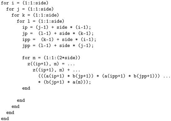
Figure 8.
Algorithm in MATLAB.
The C-code version was then be mapped to Verilog HDL using behavioral, RTL and structural level design descriptions using different programming styles that would target different requirements from early-stage prototyping and debugging to physical hardare implementation in an ASIC or FPGA. For example, Figure 9 shows the for-loops in Verilog HDL for behavioral modelling and simulation. This description would not be suitable for synthesis into logic, but would be used for algorithm verification purposes to ensure the different design descriptions have the same functionality. In the behavioral model shown here, a time delay (#5 time units) was included for simulation purposes to enable the data changes to be visualized in simulation. It also allows timing considerations for a design description to be synthesized into logic to be included:
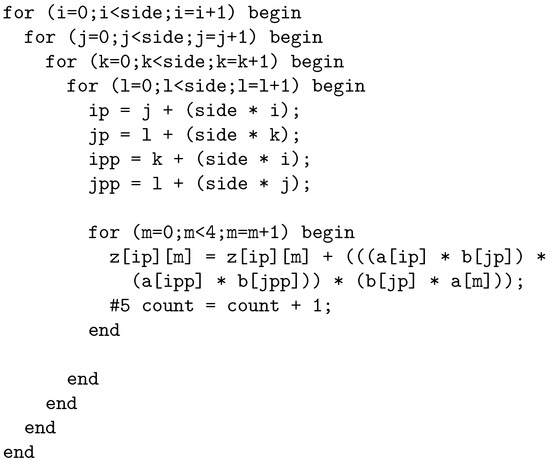
Figure 9.
Algorithm in Verilog HDL using for-loops.
Example
For example, considering input array values as (Figure 10):
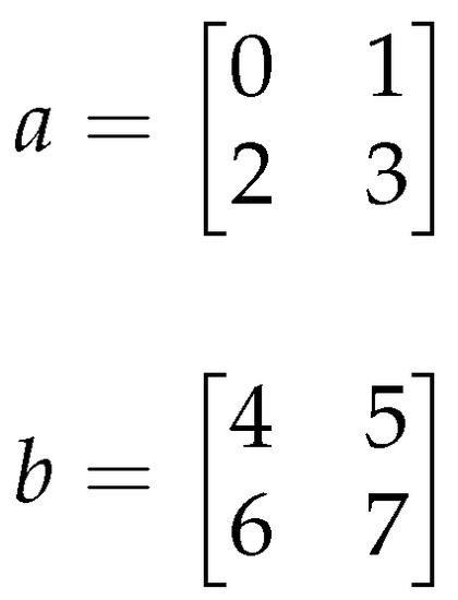
Figure 10.
Input arrays a and b.
The results array (z) is (Figure 11):
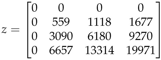
Figure 11.
Results array z.
With these arrays, Figure 12 shows a set of simulation results for the for-loop model. This shows the loop counter variable values as well as the input and output array values. Analysis of the values as they change on each iteration of the nested for-loops enables an understanding of how the data changes and this information could be used to optimize the hardware required in an implementation.
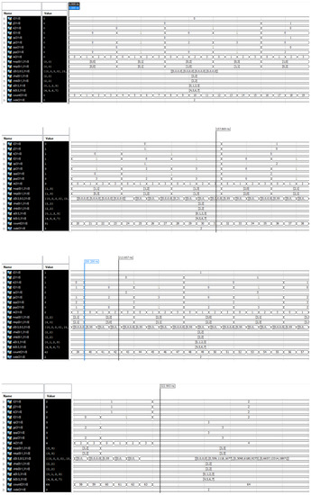
Figure 12.
Verilog HDL for-loop behavioral model simulation results (top to bottom order of the waveform plots shows the start to end of simulation run).
With this model, the input array values have been preset and for an initial behavioural simulation, the hardware design description does not have any physical inputs or outputs, the same way the C-code version operates. For a realistic hardware implementation, the design would allow for the input array values to be set from an external source as well as supporting access to the output (results) array using physical wires.
For implementation in physical hardware, either in a FPGA or ASIC, design details need to be included as the designer would require a detailed specification in order to create the required hardware realization of the algorithm. For example, would fixed-point or floating-point arithmetic be used, what would be the word length of the data, what timing requirements are to be met, circuit size, power consumption, and cost?
With this case study design, the behavioral model was redesigned at RTL and structural levels to support synthesis and implementation. To achieve this, the for-loops were replaced with a counter and state machine arrangement that represented the functionality of the for-loops and to support design synthesis into logic. The Xilinx Artix-7 FPGA incorporating a MicroBlaze processor was used as a prototyping platform for the algorithm development and verification. Both the C-code version (software) and the Verilog HDL version (hardware) were incorporated in the FPGA for evaluation purposes. The synthesized Verilog HDL model was packaged as an IP (intellectual property) block and connected to the MicroBlaze processor bus. Software functions running on the microprocessor were developed to access the IP block.
The top level block diagram for the FPGA based design (with annotations) is shown in Figure 13. A Python script running on the PC connected to the FPGA via a USB (Universal Serial Bus) connected allowed access to the microprocessor via a UART (Universal Asynchronous Receiver Transmitter) physical interface.
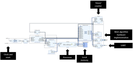
Figure 13.
MicroBlaze processor system top level block diagram.
The Processor core is supported with peripheral circuits (peripheral to the processor but still internal to the FPGA design). Clock and reset inputs provide the external control and a 32-kByte Local memory provides the processor RAM. The hardware UART provides 9600 Baud rate communications and a Timer/counter circuit allows for accurate timing of operations (if required) through the use of Timer/counter interrupts and Interrupt Service Routines (ISRs).
A simplified view of the MoA hardware design architecture is shown in Figure 14. Here, a counter/state machine circuit creates the array address and control signals along with control signals for the Computation block. The arrays are modelled as single port RAM cells in Verilog HDL. In this figure, data are shown only to be read from the memories holding array a and array b data, but are read and written to for the memory holding array z data.
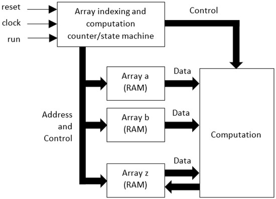
Figure 14.
Simplified view of the MoA hardware design (Verilog HDL).
However, for a full implementation, all arrays can be read from and written to, although this functionality is not shown in the figure. In addition, communication functions are not shown. The counter/state machine circuit has three basic external control signals: reset to provide a local circuit reset for initialization, clock to provide a local clock signal for the synchronous components (D-type flip-flops in this case), and run to start a computation run.
Verification of the different design implementations was undertaken in both simulation and physical circuit functional operation by comparing the array values before, during, and on completion of the computations. The values returned from the processor were viewed on a PC and compared to the software (C, Python, and MATLAB) results. With the different representations of the MoA optimized algorithm, the array values were verified to be the same on completion of the algorithm computation cycle. This identified the functionality of the different implementations, but the timing considerations (how long it took to complete the overall computation with different software and hardware implementations) and power considerations were not considered in this specific activity.
6. Conclusions
In this article, the implementation of MoA optimized algorithms on custom architecture hardware-software co-design were discussed, and options to their realizations presented.
Where a complex set of operations on tensors are to be performed, these can be optimized to nested for-loop structures that will access data in contiguous memory. How these for-loop arrangements are arranged to access data and the tensor shape information in hardware, software or as hardware-software co-designs, is a design decision based on a complex set of requirements such as the available technology and designer experience.
Within the article, requirements and choices were identified and discussed. With reference to an example tensor product, the MoA optimized algorithm is implemented in different software languages and in hardware as a synthesized HDL design description using Verilog HDL. With this, different approaches to realizing such algorithms can be investigated.
Author Contributions
L.M. was the key lead on the MoA and algorithm development, along with the derivation of the array details. I.A.G. provided the key lead in the electronic system design and implementation. Both authors equally contributed to the writing of the article. All authors have read and agreed to the published version of the manuscript.
Funding
This research received no external funding.
Conflicts of Interest
The authors declare no conflict of interest.
Abbreviations
The following abbreviations are used in this manuscript:
| AI | Artificial Intelligence |
| ASIC | Application Specific Integrated Circuit |
| CPU | Central Processing Unit |
| CR | Church-Rosser |
| DGEMM | Double-precision, GEneral Matrix-matrix Multiplication |
| DL | Deep Learning |
| DMA | Direct Memory Access |
| DNF | Denotational Normal Form |
| FFT | Fast Fourier Transform |
| FPGA | Field Programmable Gate Array |
| GEMM | GEneral Matrix-matrix Multiplication |
| GPU | Graphics Processing Unit |
| HDL | Hardware Description Language |
| HP | Hadamard Product |
| IP | Intellectual Property |
| ISR(s) | Interrupt Service Routine(s) |
| KP | Kronecker Product |
| KR | Khatri-Rao |
| LU | LU Decomposition |
| ML | Machine Learning |
| MM | Matrix Multiplication |
| MoA | Mathematics of Arrays |
| ONF | Operational Normal Form |
| OS(es) | Operating System(s) |
| PC | Personal Computer |
| PIM | Processing in Memory |
| QR | QR Decomposition |
| RISC | Reduced Instruction Set Computer |
| RMA | Remote Memory Access |
| RNN(s) | Recurrent Neural Network(s) |
| RTOS | Real-Time Operating System |
| TPU | Tensor Processing Unit |
| UART | Universal Asynchronous Receiver Transmitter |
| USB | Universal Serial Bus |
| VHDL | VHSIC (Very High Speed Integrated Circuit) HDL |
References
- Google. TensorFlow. 2022. Available online: https://www.tensorflow.org (accessed on 1 September 2022).
- Ahmad Shawahna, S.M.S.; El-Maleh, A. FPGA-Based Accelerators of Deep Learning Networks for Learning and Classification: A Review. IEEE Access 2018, 7, 7823–7859. [Google Scholar] [CrossRef]
- Intel Corporation. Intel(C) Core(TM) Processor Family. 2022. Available online: https://www.intel.co.uk/content/www/uk/en/products/details/processors/core.html (accessed on 1 September 2022).
- NVIDIA Corporation. NVIDIA Technologies. 2022. Available online: https://www.nvidia.com/en-us/technologies/ (accessed on 1 September 2022).
- Google. Cloud TPU. 2022. Available online: https://cloud.google.com/tpu/ (accessed on 1 September 2022).
- Advanced Micro Devices, Inc. FPGAs & 3D ICs. 2022. Available online: https://www.xilinx.com/products/silicon-devices/fpga.html (accessed on 1 September 2022).
- Arm Limited. Whitepaper: Lowering the barriers to entry for ASICs. 2022. Available online: https://community.arm.com/designstart/b/blog/posts/whitepaper-lowering-the-barriers-to-entry-for-asics (accessed on 1 September 2022).
- Mullin, L.M.R. A Mathematics of Arrays. Ph.D. Thesis, Syracuse University, Syracuse, NY, USA, 1988. [Google Scholar]
- Python. 2022. Available online: https://www.python.org/ (accessed on 1 September 2022).
- ISO/IEC 9899:2018; Information Technology—Programming Languages—C. International Organization for Standardization (ISO): Geneva, Switzerland, 2022. Available online: https://www.iso.org/standard/74528.html (accessed on 1 September 2022).
- Institute of Electrical and Electronics Engineers (IEEE). 1364-2005—IEEE Standard for Verilog Hardware Description Language. 2022. Available online: https://ieeexplore.ieee.org/document/1620780 (accessed on 1 September 2022).
- Xilinx. Artix 7. 2022. Available online: https://www.xilinx.com/products/silicon-devices/fpga/artix-7.html (accessed on 1 September 2022).
- Wolfe, M. Performant, Portable, and Productive Parallel Programming with Standard Languages. Comput. Sci. Eng. 2021, 23, 39–45. [Google Scholar] [CrossRef]
- Thomas, S.; Mullin, L.; Świrydowicz, K.; Khan, R. Threaded Multi-Core GEMM with MoA and Cache-Blocking. In Proceedings of the 2021 World Congress in Computer Science, CSCE’21, Las Vegas, NV, USA, 26–29 July 2021. [Google Scholar]
- Thomas, S.; Mullin, L.; Świrydowicz, K. Improving the Performance of DGEMM with MoA and Cache-Blocking. In Proceedings of the Array 2021, ACM, Online, 20–26 June 2021. [Google Scholar]
- NumPy. NumPy. 2022. Available online: https://numpy.org/ (accessed on 1 September 2022).
- Xilinx. MicroBlaze Soft Processor Core. 2022. Available online: https://www.xilinx.com/products/design-tools/microblaze.html (accessed on 1 September 2022).
- Hunt, H.B.; Mullin, L.R.; Rosenkrantz, D.J.; Raynolds, J.E. A Transformation–Based Approach for the Design of Parallel/Distributed Scientific Software: The FFT. arXiv 2008, arXiv:cs.SE/0811.2535. [Google Scholar]
- Mullin, L.; Phan, W. A Transformational Approach to Scientific Software: The Mathematics of Arrays (MoA) FFT with OpenACC. In Proceedings of the OpenACC Summit 2021, Remote Event, 14–15 September 2021. [Google Scholar]
- Mullin, L.; Thibault, S. A Reduction Semantics for Array Expressions: The Psi Compiler; Technical Report, CSC-94-05; University Missouri-Rolla: Rolla, MO, USA, 1994. [Google Scholar]
- Ostrouchov, C.; Mullin, L. PythonMoA. Available online: https://labs.quansight.org/blog/2019/04/python-moa-tensor-compiler/ (accessed on 1 September 2022).
- Gibbons, J. (Ed.) Proceedings of the 6th ACM SIGPLAN International Workshop on Libraries, Languages and Compilers for Array Programming, ARRAY@PLDI 2019, Phoenix, AZ, USA, June 22, 2019; Association for Computing Machinery: New York, NY, USA, 2019. [Google Scholar] [CrossRef]
- Chetioui, B.; Abusdal, O.; Haveraaen, M.; Järvi, J.; Mullin, L. Padding in the Mathematics of Arrays. In Proceedings of the 8th ACM SIGPLAN International Workshop on Libraries, Languages and Compilers for Array Programming, Virtual Event, 21 June 2021. [Google Scholar]
- Chetioui, B.; Larney, M.K.; Jarvi, J.; Haveraaen, M.; Mullin, L. P3 Problem and Magnolia Language: Specializing Array Computations for Emerging Architectures. Front. Comput. Sci. Sect. Softw. 2022. to appear. [Google Scholar] [CrossRef]
- Zhang, H.; Ding, F. On the Kronecker Products and Their Applications. J. Appl. Math. 2013, 2013, 296185. [Google Scholar] [CrossRef]
- Acar, A.; Anandkumar, A.; Mullin, L.; Rusitschka, S.; Tresp, V. Tensor Computing for Internet of Things (Dagstuhl Perspectives Workshop 16152). Dagstuhl Rep. 2016, 6, 57–79. [Google Scholar] [CrossRef]
- Thakker, U.; Beu, J.G.; Gope, D.; Zhou, C.; Fedorov, I.; Dasika, G.; Mattina, M. Compressing RNNs for IoT devices by 15-38x using Kronecker Products. arXiv 2019, arXiv:1906.02876. [Google Scholar]
- Mullin, L.R.; Raynolds, J.E. Scalable, Portable, Verifiable Kronecker Products on Multi-scale Computers. In Constraint Programming and Decision Making; Ceberio, M., Kreinovich, V., Eds.; Springer: Cham, Switzerland, 2014; Volume 539, pp. 111–129. [Google Scholar] [CrossRef]
- Gustafson, J.; Mullin, L. Tensors Come of Age: Why the AI Revolution Will Help HPC. arXiv 2017, arXiv:1709.09108. [Google Scholar]
- Mullin, L.R. A uniform way of reasoning about array-based computation in radar: Algebraically connecting the hardware/software boundary. Digit. Signal Process. 2005, 15, 466–520. [Google Scholar] [CrossRef]
- Mullin, L.R.; Raynolds, J.E. Conformal Computing: Algebraically connecting the hardware/software boundary using a uniform approach to high-performance computation for software and hardware applications. arXiv 2008, arXiv:0803.2386. [Google Scholar]
- Chetioui, B.; Mullin, L.; Abusdal, O.; Haveraaen, M.; Järvi, J.; Macià, S. Finite difference methods fengshui: Alignment through a mathematics of arrays. In Proceedings of the 6th ACM SIGPLAN International Workshop on Libraries, Languages and Compilers for Array Programming, Phoenix, AZ, USA, 22 June 2019. [Google Scholar]
- Berkling, K. Arrays and the Lambda Calculus; Technical Report 93; SU-CIS-90-22; Syracuse University: Syracuse, NY, USA, 1990. [Google Scholar]
- Iverson, K.E. A Programming Language; John Wiley and Sons, Inc.: Hoboken, NJ, USA, 1962. [Google Scholar] [CrossRef]
- Abrams, P.S. An APL Machine. Ph.D. Thesis, Stanford University, Stanford, CA, USA, 1970. [Google Scholar]
- Grout, I.; Mullin, L. Hardware Considerations for Tensor Implementation and Analysis Using the Field Programmable Gate Array. Electronics 2018, 7, 320. [Google Scholar] [CrossRef]
- Grout, I.; Mullin, L. Realization of the Kronecker Product in VHDL using Multi-Dimensional Arrays. In Proceedings of the 2019 7th International Electrical Engineering Congress (iEECON), Cha-am, Thailand, 6–8 March 2019. [Google Scholar] [CrossRef]
- Mullin, L.M.R.; Jenkins, M.A. Effective data parallel computation using the Psi calculus. Concurr. Pract. Exp. 1996, 8, 499–515. [Google Scholar] [CrossRef]
- Anandkumar, A. Role of Tensors in Machine Learning. Available online: https://developer.download.nvidia.com/video/gputechconf/gtc/2019/presentation/s9733-role-of-tensors-in-machine-learning.pdf (accessed on 1 September 2022).
- Cadence Design Systems, Inc. Ten Reasons to Optimize a Processor. 2022. Available online: https://ip.cadence.com/uploads/770/TIP_WP_10Reasons_Customize_FINAL-pdf (accessed on 1 September 2022).


Publisher’s Note: MDPI stays neutral with regard to jurisdictional claims in published maps and institutional affiliations. |
© 2022 by the authors. Licensee MDPI, Basel, Switzerland. This article is an open access article distributed under the terms and conditions of the Creative Commons Attribution (CC BY) license (https://creativecommons.org/licenses/by/4.0/).