Article

Sub-Tree-Based Approach for Reconfiguration of Light-Tree Pair without Flow Interruption in Sparse Wavelength Converter Network

by
Amanvon Ferdinand Atta
1,*,
Joël Christian Adépo
2,
Bernard Cousin
3 and
Souleymane Oumtanaga
1
1
Laboratoire de Recherche en Informatique et Télécommunication, Institut National Polytechnique Félix Houphouët-Boigny, Yamoussoukro BP 1093, Côte d’Ivoire
2
Unité de Recherche et d’Expertise Numérique, Université Virtuelle de Côte d’Ivoire, Abidjan BP 536, Côte d’Ivoire
3
Institut de Recherche en Informatique et Systèmes Aléatoires, Université de Rennes 1, 35000 Rennes, France
*
Author to whom correspondence should be addressed.
Information 2021, 12(5), 211; https://doi.org/10.3390/info12050211
Submission received: 19 April 2021 / Revised: 1 May 2021 / Accepted: 14 May 2021 / Published: 17 May 2021
(This article belongs to the Section Information and Communications Technology)

Abstract

:
Network reconfiguration is an important mechanism for network operators to optimize network performance and optical flow transfer. It concerns unicast and multicast connections. Multicast connections are required to meet the bandwidth requirements of multicast applications, such as Internet Protocol-based TeleVision (IPTV), distance learning, and telemedicine. In optical networks, a multicast connection is made possible by the creation of an optical tree-shaped path called a light-tree. The problem of light-tree pair reconfiguration is addressed in this study. Given an initial light-tree used to transfer an optical flow and a final light-tree that is computed by the network operator to optimize network performance, the goal is to migrate the optical flow from the initial light-tree to the final light-tree without flow interruption. Flow interruption is not desirable for network operators because it forces them to pay financial penalties to their customers. To solve this problem, existing methods use a branch approach that is inefficient if some network nodes do not have wavelength conversion capability. Therefore, we proposed in this study a sub-tree-based method. This approach selects and configures sub-tree pairs from the light-tree pair (initial light-tree, final light-tree) to be reconfigured. Then, we produce a sequence of configurations. The performance study confirms that our method is efficient in solving the problem of light-tree pair reconfiguration because our method does not cause flow interruption.

1. Introduction

1.1. Context

Wavelength Division Multiplexing (WDM) is a multiplexing technology that provides enormous bandwidth to meet the bandwidth requirements of applications. In a single optical fiber, WDM creates multiple communication channels at various wavelengths [1]. A WDM network consists of a set of optical fibers connected by optical nodes that use WDM as a multiplexing technology [2]. A wavelength converter [3] is a key node component that contributes to reducing the blocking probability in a WDM network. However, wavelength converters are still expensive, and the wavelength converter technology is not very mature [4,5]. Therefore, a network in which few nodes are equipped with a wavelength converter is more practical [5,6]. A WDM optical network with a small fraction of optical nodes having a wavelength conversion capability is called a sparse wavelength converter network [7].
Recently, multicast applications such as videoconferencing, weather forecasting, distance learning, online video games, and Internet Protocol-based TeleVision (IPTV) have become increasingly popular according to Cisco’s annual internet report (2018–2023) [8]. Hence, multicast communication was introduced in the WDM network to make more efficient use of optical resources, such as wavelengths. To do this, the problem of MultiCast Routing and Wavelength Assignment (MC-RWA) has been addressed in several works, such as in [9,10,11,12]. One of the most common solutions for solving this problem is the light-tree  [13]. A light-tree is a tree-shaped path [14] that is formed by a set of wavelength channels for transferring an optical flow (in an all-optical manner) from a source node to destination nodes. Note that each link of this tree-shaped path is called a wavelength channel. In addition, all wavelength channels of this tree-shaped path use the same wavelength.
In a WDM network, some events such as the increasing number of connection requests trigger a reconfiguration of optical paths. Optical path reconfiguration consists of establishing a new path in the WDM network and deleting a current path. Optical path reconfiguration can be used to allow the network to support an increasing number of connections (i.e., to reduce the blocking probability) [15]. An optical path may be a lightpath [16] (used by unicast applications) or a light-tree (used by multicast applications). Reconfiguration that concerns lightpaths has been intensively studied, unlike reconfiguration that concerns light-trees [17]. Due to the increasing popularity of multicast applications, this study focuses on reconfiguration that concerns light-trees.
This paragraph illustrates how reconfiguration that concerns light-trees can be used to support the increasing number of connections. In Figure 1a–c, the set of nodes and the set of black links form the physical topology of the network. Figure 1a shows three established connections. There is a multicast connection < s , { d 1 , d 2 } > whose established path is represented by the set of established wavelength channels (using wavelength ω 1 ) in solid blue. In addition, there is a unicast connection < a , { c } > whose established path is represented by the set of wavelength channels (in solid green) established successively on the optical fiber connecting node a to node d 2 by using wavelength ω 2 and on the optical fiber connecting node d 2 to node c by using wavelength ω 2 . Then, there is a unicast connection < b , { d 2 } > whose established path is represented by the wavelength channel (in solid green) established on the optical fiber connecting node b to node d 2 by using wavelength ω 2 . Assume that each optical fiber has a capacity of two wavelengths (i.e., ω 1 and ω 2 ) available for the routing operation. Let < a , { d 2 } > be a new unicast connection to be established. The wavelengths ω 1 and ω 2 are not idle on the optical fiber connecting node a to node d 2 ( i ) . Furthermore, wavelength ω 2 is idle on the optical fiber connecting node a to node s and on the optical fiber connecting node s to node b. However, only wavelength ω 1 is idle on the optical fiber connecting node b to node d 2 , and node b does not have wavelength conversion capability. Thus, node b cannot convert wavelength ω 2 to wavelength ω 1 . Therefore, the optical path using wavelength ω 2 on the optical fibers connecting node a to node s, and node s to node b and using wavelength ω 1 on the fiber connecting node b to node d 2 cannot be used as the optical path to establish < a , { d 2 } > ( i i ) . Similarly, the optical path using wavelength ω 2 on the optical fibers connecting node a to node d 1 , and node d 1 to node c and using wavelength ω 1 on the fiber connecting node c to node d 2 cannot be used as the optical path to establish the new unicast connection < a , { d 2 } > ( i i i ) . From ( i ) , ( i i ) and ( i i i ) , it results that no optical path can be used to establish that < a , { d 2 } > : < a , { d 2 } > is blocked.
To overcome this blocking situation of the new connection < a , { d 2 } > , the network operation decides at first to recompute a new routing for the multicast connection < s , { d 1 , d 2 } > . This new routing is the new light-tree (also called the final light-tree) represented by the set of wavelength channels (in dotted blue) to be established in Figure 1b. Next, the network operator performs optical path reconfiguration. In short, the network operator performs the establishment of the wavelength channels of the final light-tree and the deletion of the wavelength channels of the initial light-tree. After this light-tree pair reconfiguration, wavelength ω 1 is idle on the optical fiber connecting node a and node d 2 . Hence, Figure 1c shows that the unicast connection < s , { d 2 } > is established because there is an optical path represented by the wavelength channel (in solid blue) between nodes a and d 2 .

1.2. Problem Overview

The reconfiguration problem studied here is the problem of a light-tree pair reconfiguration. Given an initial light-tree used to transfer an optical flow of a given multicast connection and a final light-tree of this given multicast connection, which allows supporting the increasing number of connections, the goal is to migrate the optical flow from the initial light-tree to the final light-tree without flow interruption. Flow interruption must be avoided because it disrupts the running of user’s applications. This obliges network operators to pay financial penalties to customers that are affected by flow interruptions  [18].
This problem of a light-tree pair reconfiguration previously mentioned is tricky because most of the time, the initial light-tree and the final light-tree share resources such as wavelength channels. This situation of resource sharing (between the two light-trees) requires going through one or more transient configurations with the use of some spare wavelengths and wavelength conversions to avoid flow interruptions  [19]. A configuration is a set of wavelength channels required to transfer an optical flow at a reconfiguration step. Moreover, wavelength conversion is not always possible in our study because in a sparse wavelength converter network, some nodes do not have wavelength conversion capability. A spare wavelength is a wavelength that is not required by the initial light-tree and the final light-tree. As a wavelength is a precious resource, our solution must use spare wavelengths parsimoniously because a spare wavelength can be used by other critical tasks such as network survivability (e.g., path protection and path recovery)  [20].
In short, the reconfiguration problem studied here is to find the sequence of configurations required to migrate an optical flow without flow interruption from an initial light-tree to a final light-tree without flow interruption while minimizing the use of spare wavelengths. The three reconfiguration primitives [21] are useful for building a sequence of configurations:
  • New sub-paths pre-establishment denoted by PREESTAB_SPs(New_SUBPATHS, ω ): based on node configuration operation, such as the addition of wavelength switching [21], PREESTAB_SPs returns the set of established wavelength channels (using wavelength ω ) required for the simultaneous pre-establishment of the sub-paths belonging to New_SUBPATHS. This set of established wavelength channels is added to the current configuration to obtain a new configuration.
  • Optical flow switching denoted by SWITCH(CUR_SUBPATHS,NEW_SUBPATHS, ω ): based on a node configuration operation called changeover, which combines other operations such as the addition, the deletion of wavelength switching and the wavelength conversion [21]. SWITCH returns the set of established wavelength channels (using wavelength ω ) required to simultaneously switch an optical flow from the current sub-paths (belonging to CUR_SUBPATHS) to the new sub-paths belonging to NEW_SUBPATHS. This set of established wavelength channels is added from the current configuration to obtain a new configuration. Note that SWITCH uses a set of switching nodes such that each switching node belongs to a sub-path pair (i.e., a current sub-path belonging to CUR_SUBPATHS, a new sub-path belonging to NEW_SUBPATHS). In addition, the default value of the switching node of a sub-path pair is the common root node of this sub-path pair.
  • Current sub-paths deletion by DELETE_SPs(CUR_SUBPATHS, ω : based on node configuration operations such as the deletion of wavelength switching, DELETE_SPs returns the set of established wavelength channels (using wavelength ω ) required for the simultaneous deletion of the sub-paths belonging to CUR_SUBPATHS. This set of established wavelength channels is deleted from the current configuration to obtain a new configuration.
Note that for each of the three previous primitives, wavelength ω may be a spare wavelength. In addition, a sub-path belonging to CUR_SUBPATHS must be selected from the current light-tree, which is the initial light-tree at the beginning of the reconfiguration. Then a sub-path belonging to NEW_SUBPATHS must be selected from the final light-tree.

1.3. Contribution and Outline of Paper

Until now, some methods that use a so-called branch approach [21] have been proposed to solve the problem of light-tree pair reconfiguration. In the branch approach, a new sub-path (respectively, a current sub-path) required by a reconfiguration primitive is a branch of the final light-tree (respectively, the current light-tree). A branch of a light-tree is a sub-path of this light-tree that connects the root node to a destination node of this light-tree. The branch approach selects a set of branch pairs and uses PRESTAB_SPs, SWITCH, and DELETE_SPs successively in a one or two phase-process to build the sequence of configurations. In the branch approach, a switching node required by SWITCH must have the wavelength conversion capability. Therefore, the branch approach is not appropriate in the context of a sparse wavelength converter network. Indeed, a branch pair, which is selected from the light-tree pair, may cause flow interruption to at least one destination node. For this reason, we propose a method based on a sub-tree approach. It is important to note that, for a given set of sub-path pairs (i.e., branch pairs or sub-tree pairs), the successive use of PRESTAB_SPs, SWITCH, and DELETE_SPs refers to the reconfiguration of this set of sub-paths. The main contributions of this study are summarized as follows:
  • Characterization of sub-tree pairs to know how to select sub-tree pairs from a light-tree pair to be reconfigured.
  • Proof of simultaneous reconfigurability of a set of sub-tree pairs.
  • A method denoted by LRASRS to solve the reconfiguration problem. This method is based on the two aforementioned contributions.
The rest of this paper is organized as follows. Section 2 covers the related works. Section 3 refers to problem formulation. Section 4 explains our methodology in detail. The setting of simulations and the performance criteria are described in Section 5, and the results and discussion are presented in Section 6. Finally, Section 7 concludes the study.

2. Related Works

MBB_1 [19] was proposed to solve the problem stated in Section 1.2. MBB_1 is an extension of the Make Before Break (MBB [22,23]) policy. Note that MBB is used for any unicast path (i.e., lightpath) reconfiguration. MBB_1 produces the sequence of configurations by applying MBB policy on each branch pair (a current branch belonging to the initial light-tree, a new branch belonging to the final light-tree). In addition, MBB_1 does not use spare wavelengths. Therefore, for a branch pair (a current branch, a new branch), if the new branch (belonging to the final light-tree) shares at least one link with the current branch (belonging to the initial light-tree), then MBB_1 causes flow interruption to at least one destination node.
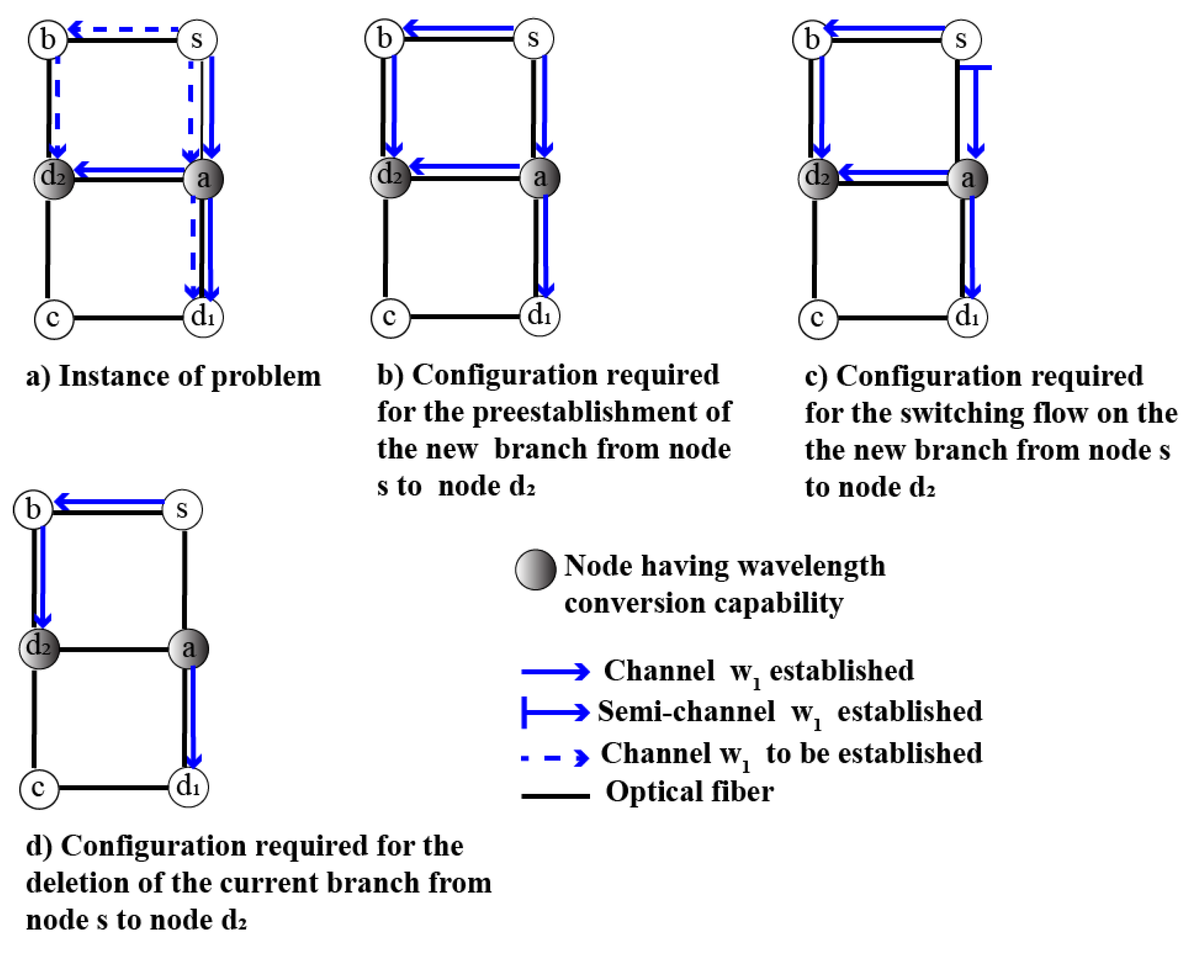
In Figure 2a–d, the set of nodes and the set of black links form the physical topology of the network. Figure 2a shows a problem instance that concerns the multicast connection < s , { d 1 , d 2 } > : the set of links in solid blue forms the initial light-tree, and the set of links in dotted blue forms the final light-tree. For this instance of the problem, only the branch pair ( { s { a { d 2 } } , { s { b { d 2 } } ) leading to node d 2 needs to be reconfigured. As can be seen in Figure 2c, the configuration required for the optical flow switching to the new branch { s { b { d 2 } } } causes a flow interruption to node d 1 because the wavelength semi-channel established between node s and node a does not allow node a to receive the optical flow.
Note that a wavelength semi-channel is a wavelength channel such that one of its end nodes has not been configured. Therefore, a wavelength semi-channel is not fully established to transfer an optical flow. In addition, the configuration required for the deletion of the current branch { s { a { d 2 } } } causes a flow interruption to node d 1 (see Figure 2d) despite the fact that there is a wavelength channel established between node a and node d 1 because no wavelength channel is established between node s and node a, and therefore, no optical path is fully configured between the source node s and node d 1 .
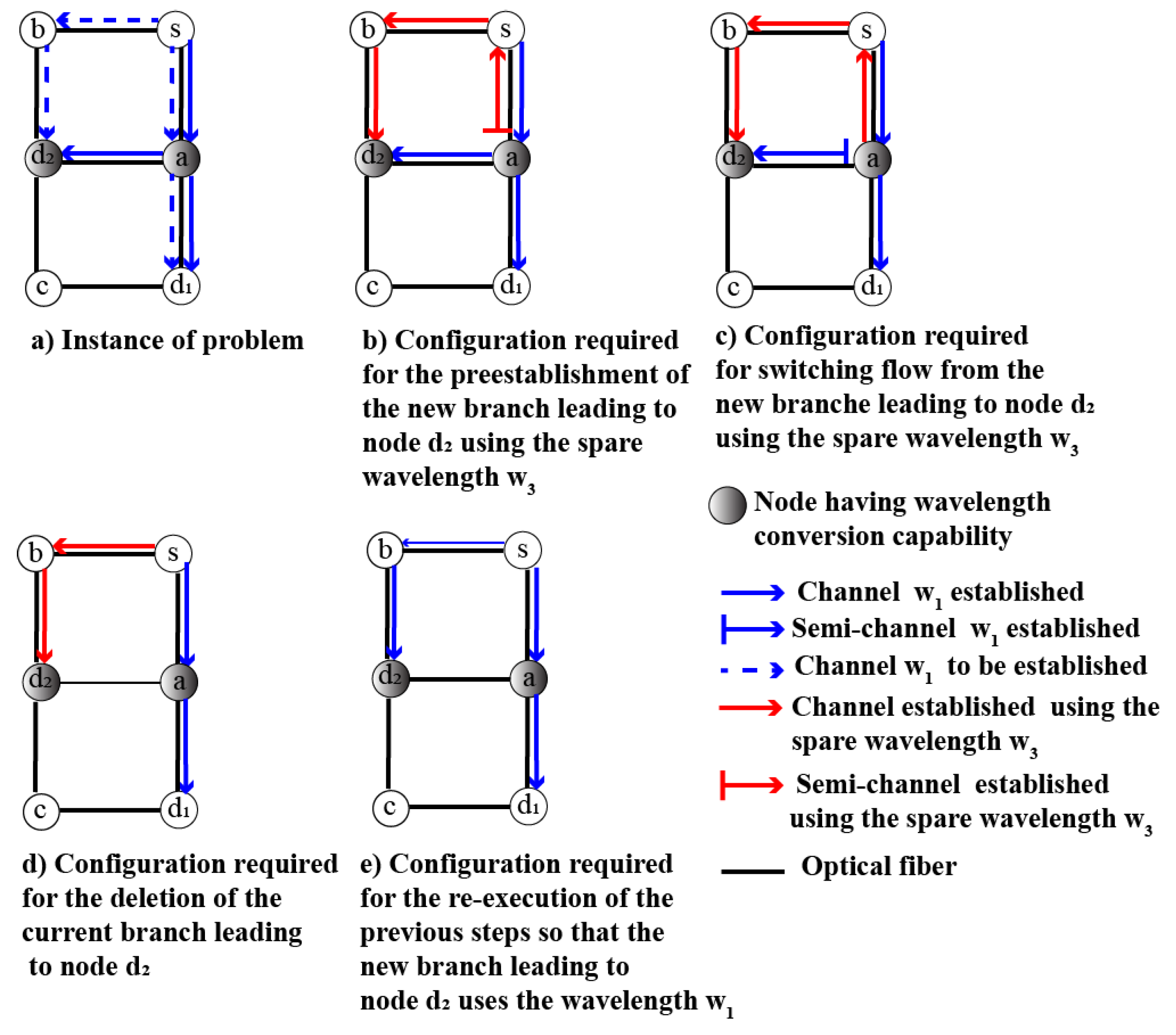
BpBAR_2 [21] was proposed to migrate an optical flow from an initial light-tree to a final light-tree without flow interruption. BpBAR_2 is also a branch-based method. Unlike MBB_1, the switching node for a branch pair is not necessarily the root of the light-tree pair, and BpBAR_2 uses a spare wavelength for each branch pair. In other words, BpBAR_2 introduced a function to compute a suitable switching node to avoid flow interruptions. It is important to note that if a switching node is different from the root of the light-tree pair, then it must have wavelength conversion capability. For the problem instance shown in Figure 3a, which concerns the multicast connection < s , { d 1 , d 2 } > , only the branch pair leading to node d 2 must be reconfigured. For this branch pair, BpBAR_2 selects node a as the switching node.
Figure 3b–d illustrates a sequence of configurations that avoids flow interruption because each of these configurations contained a fully configured path between node s and destination node d 1 and a fully configured path between node s and destination node d 2 .
BpBAR_2 may perform reconfiguration without flow interruption, but it results in high use of spare wavelengths. To reduce the high use of spare wavelengths, TRwRC [19] was proposed. To do this, TRwRC produces a sequence of sets of light-trees at each step of the reconfiguration process. Therefore, TRwRC finds a long sequence of configurations. RCBRwPR [24] was proposed to build a short sequence of configurations. To do this, RCBRwPR reconfigures a set of branch pairs simultaneously at each step.
In summary, MBB_1 may cause flow interruptions. In other words, for a given branch pair (a current branch, a new branch), if the new branch of this pair shares at least one link with the current branch of this pair, then MBB_1 causes flow interruptions. With other branch-based methods such as RCBRwPR or BpBAR_2, a switching node must have wavelength conversion capability. Thus, these methods are efficient in a WDM network where all nodes have wavelength conversion capability. However, in a sparse wavelength converter network, some nodes do not have wavelength conversion capability. Therefore, branch-based methods for a light-tree pair reconfiguration may generate flow interruptions in a sparse wavelength converter network. For example, with the problem instance shown in Figure 3a, if node a does not have wavelength conversion capability, then the configuration obtained after the optical flow switching to the new branch leading to node d 2 causes flow interruption towards nodes d 1 and d 2 .
To the best of our knowledge, no method has been proposed to solve the problem of light-tree pair reconfiguration in a sparse wavelength converter network.

3. Problem Formulation

Let G V , E be an undirected graph that represents a sparse wavelength converter network. V is the set of nodes and E is the set of links (i.e., optical fibers). Ω is the set of wavelengths usable in each link e E of the network. In practice, Ω = Ω e Ω s for each link, where Ω e denotes the subset of wavelengths usable for computing an optical path that allows establishing a connection, and Ω s denotes the subset of wavelengths usable temporarily to configure an optical path or in a network survivability task. A wavelength that belongs to Ω s is a spare wavelength.
For a multicast connection M C r , D , an initial light-tree denoted by T 0 = V 0 , E 0 ω 0 is used to transfer the optical flow from the source node r to the destination nodes belonging to D. Note that V 0 V , E 0 E , r V 0 and D V 0 \ { r } . E 0 ω 0 = i = 1 i = E 0 e i ω 0 denotes the set of established wavelength channels forming T 0 , with ω 0 Ω e . The initial light-tree also refers to the initial configuration C 0 .
The final light-tree for the multicast connection M C r , D is denoted as T f = V f , E f ω 0 . T f is rooted at r and spanning D, with V f V , E f E , r V f and D V f \ { r } . E f ω 0 = i = 1 i = E f e i ω 0 is the set of wavelength channels forming T f . The final light-tree also refers to the final configuration C n . However, the final light-tree T f may share some links (i.e., wavelength channels) with the initial light-tree T 0 . Therefore, some transient configurations must be found before to obtain the final configuration C n . In other words, a sequence of configurations S C = < C 0 , C 1 , , C n 1 , C n > must be built, where C k (with k 1 ) is obtained by adding or deleting the set of wavelength channels returned by a reconfiguration primitive belonging to {PREESTAB_SPs, SWITCH, DELETE_SPs}.
However, a transient configuration C k can cause a high rate of flow interruptions to the destination nodes belonging to D if some inappropriate nodes are configured. In this case, ∃ d D such that there is no fully configured optical path between the source node r of M C r , D and the destination node d. Note that an optical path is not fully configured if it contains at least one of its wavelength channels that is not established or if this optical path contains at least one wavelength semi-channel.
Let i n t e r r u p t _ r a t e C k be the rate of flow interruptions caused by the transient configuration C k (which is different from C 0 and C n , where n = S C 1 ), with 1 k S C 2 . This rate is defined by Equation (1):
i n t e r r u p t _ r a t e C k   =   d D C k r , d D
where
C k ( r , d ) = 1 if   the   path   between   r   and   d   is   not   fully   configured 0 otherwise .
Thus, the average rate of flow interruptions of the sequence of configurations is defined by Equation (2):
i n t e r r u p t _ r a t e S C = k = 1 S C 2 i n t e r r u p t _ r a t e C k S C 2
The wavelength channels belonging to the transient configuration C k can use a spare wavelength. However, spare wavelengths must be used parsimoniously [20]. Hence, some wavelength channels (but not all) of a transient configuration C k may use a spare wavelength.
Let a d d _ c o s t S C be the cost of spare wavelengths caused by the sequence of configurations S C = < C 0 , C 1 , , C n > . This cost is the total number of wavelength channels requiring a spare wavelength. Let a d d _ c o s t C k be the number of wavelength channels (belonging to configuration C k ) requiring a spare wavelength. a d d _ c o s t C k is defined by Equation (3):
a d d _ c o s t C k = e i ω i C k S e i ω i , C k
where
S e i ω i , C k = 1 if   wavelength   ω i used   by   e i ω i C k is   such   that   ω i Ω s 0 otherwise .
Thus, a d d _ c o s t S C is defined by Equation (4):
a d d _ c o s t S C = k = 1 S C 2 a d d _ c o s t C k
Note that each configuration C k in Equation (4) is a transient configuration because the initial configuration C 0 and the final configuration C n do not use a spare wavelength.
With all the previous notations, the problem of a light-tree pair reconfiguration is stated as follows:
  • Input: The initial light-tree T 0 , which is used to transfer an optical flow before the reconfiguration process, and the final light-tree T f .
  • Output: The sequence of configurations SC to migrate an optical flow from T 0 to T f .
  • Objective: Avoidance of flow interruptions (which corresponds to an average rate of flow interruptions equal to zero) while minimizing the cost of spare wavelengths.

4. Our Methodology

The reconfiguration primitives (see Section 1.2) were used to build the sequence of configurations. To execute these primitives flawlessly, their inputs must be properly selected. The existing methods (see Section 2) are based on a branch approach, which uses branches belonging to a selected set of branch pairs as inputs of the reconfiguration primitives. However, Section 2 shows that the branch-based methods may generate flow interruptions during a light-tree pair reconfiguration in a spare wavelength converter network. Therefore, we propose a sub-tree approach, which uses sub-trees belonging to a selected set of sub-tree pairs as inputs of the reconfiguration primitives. A sub-tree S T of a given tree T is any tree included in T.
In the following subsections, the sub-tree pairs that can be selected are first identified ( i ) . Next, the proof of the simultaneous reconfigurability of some sub-tree pairs is given ( i i ) . Finally, a sub-tree-based method that uses ( i ) and ( i i ) is proposed to solve the formulated problem of a light-tree pair reconfiguration.
The following notations are used to present this section:
  • T c : Current tree-shaped path
  • T f : Final light-tree
  • S T c : Current sub-tree of T c
  • S T f : New sub-tree of T f
  • D T S T : Subset of the destination nodes of a light-tree T such that each element of this subset is reachable from a sub-tree S T .
  • D T x y : Subset of destination nodes of a light-tree T such that each element of this subset has an ancestor on T that is on the segment (or path) from node x to node y. Note that node v is an ancestor of node w on the tree T, which means that there is a path from v to w on T.

4.1. Characterization of Sub-Tree Pairs

According to Section 1.2, reconfiguration primitives may require a spare wavelength. However, an efficient method to solve the formulated problem must use spare wavelengths parsimoniously. Therefore, the reconfiguration of the sub-tree pair S T c , S T f must use a spare wavelength as few times as possible. Let us remind you that the reconfiguration of a sub-tree pair involves the use of the reconfiguration primitives (i.e., PREESTAB_SPs, SWITCH, and DELETE_SPs), as mentioned in Section 1.3. Therefore, depending on whether the reconfiguration of the sub-tree pair S T c , S T f requires using a spare wavelength, we identify two types of sub-tree pairs: sub-tree pairs with disjointed links and sub-tree pairs with shared links.

4.1.1. Sub-Tree Pair with Disjointed Links

The sub-tree pair S T c , S T f is a sub-tree pair with disjointed links if T c (i.e., S T c also) does not share links with S T f . The common root node of the sub-tree pair S T c , S T f is the switching node of this pair. Furthermore, after applying SWITCH and DELETE_SPs, the destination nodes belonging to D T c S T c will not receive the optical flow. Therefore, to avoid flow interruption, the sub-tree pair S T c , S T f must be selected such that D T f S T f = D T c S T c . S T f does not share its links with the current sub-tree S T c . Therefore, the reconfiguration of a sub-tree pair with disjointed links does not require the use of a spare wavelength.
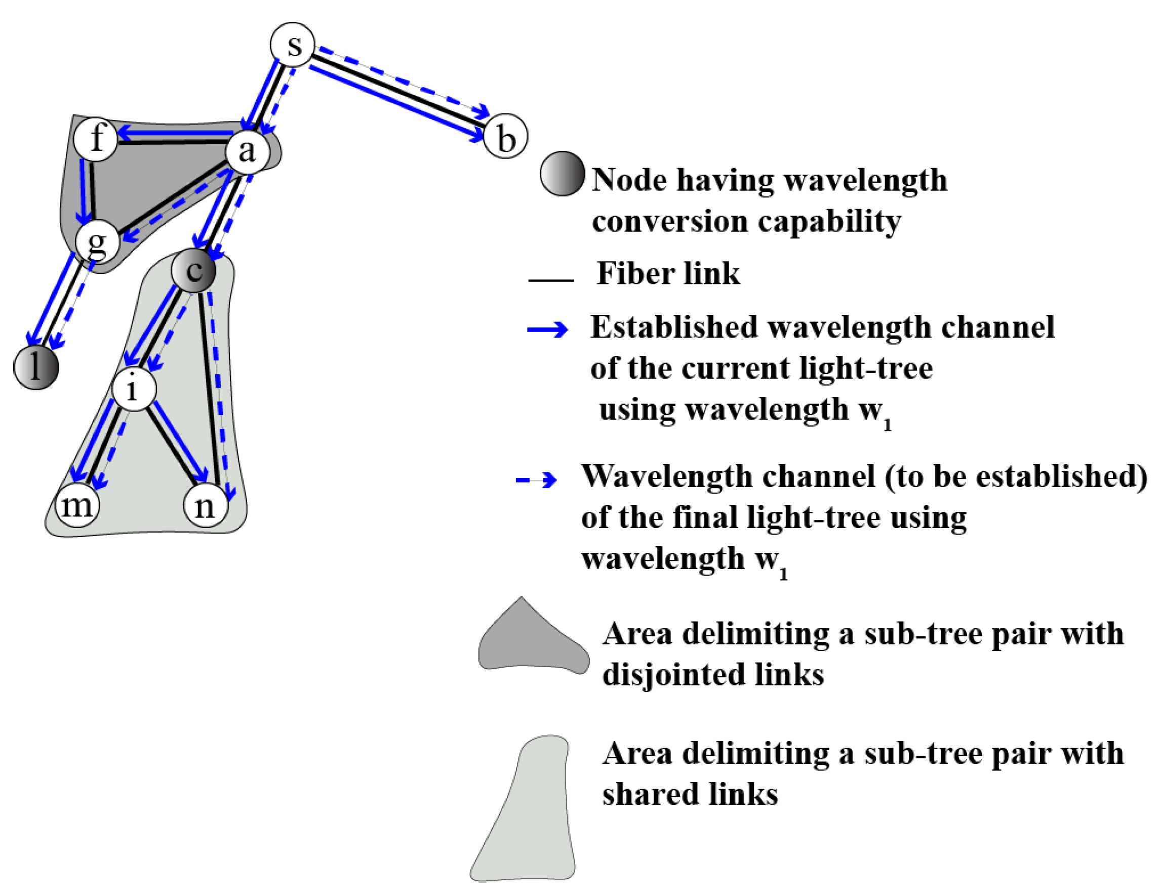
Figure 4 shows an instance of a sub-tree pair with disjointed links. In this figure, the sub-tree pair ( { a { f { g } } } , { a { g } } ) rooted at node a is a sub-tree pair with disjointed links, where { a { f { g } } } denotes the current sub-tree S T c and { a { g } } denotes the new sub-tree S T f .

4.1.2. Sub-Tree Pair with Shared Links

The sub-tree pair S T c , S T f is a sub-tree pair with shared links if S T c shares links (but not all links) with S T f . The common root node of the sub-tree pair S T c , S T f is the switching node of this pair. By construction, the root node (i.e., switching node) n s of the sub-tree pair S T c , S T f is a node that has wavelength conversion capability. Furthermore, this node is the youngest ancestor of a convergent node c g _ n o d e on both trees T c and T f such that D T c n s c g _ n o d e = D T f n s c g _ n o d e . If the convergent node c g _ n o d e does not have an ancestor that has wavelength conversion capability, then n s is the root of the tree pair T c , T f . A convergent node is a node that belongs to T c and T f . In addition, a convergent node does not have the same parent node on both trees. In short, S T c is rooted at n s and D T c n s c g _ n o d e is the set of leaf nodes of S T c . Furthermore, S T f is rooted at n s and D T f n s c g _ n o d e is the set of leaf nodes of S T f . Note that the selection of the sub-tree pair S T c , S T f , which is a sub-tree pair with shared links, avoids flow interruption because D T c n s c g _ n o d e = D T f n s c g _ n o d e . The sub-tree pair S T c , S T f is a sub-tree pair with shared links. Therefore, the reconfiguration primitives applied to this sub-tree pair require the use of a spare wavelength. In short, the reconfiguration of a sub-tree pair with shared links requires the use of a spare wavelength. Moreover, the root node n s of a sub-tree pair with shared links is the youngest ancestor of the convergent node c g _ n o d e on both T c and T f . Therefore, the reconfiguration of a sub-tree pair with shared links requires using a spare wavelength as few times as possible.
Figure 4 shows an instance of a sub-tree pair with shared links. In this figure, the sub-tree pair ( { c { i { m , n } } } , { c { i { m } , n } } ) rooted at node c is a sub-tree pair with shared links because link ( c , i ) is shared by both sub-trees of this pair. { c { i { m , n } } } denotes the current sub-tree S T c and { c { i { m } , n } } denotes the new sub-tree S T f .

4.2. Proof of Simultaneous Reconfigurability of Sub-Tree Pairs

This sub-section provides proof that the simultaneous reconfiguration of several sub-tree pairs is possible, providing a short sequence of configurations. Let S T c 1 , S T f 1 and S T c 2 , S T f 2 be two sub-tree pairs that must be reconfigured, where S T c 1 T c , S T c 2 T c , S T f 1 T f and S T f 2 T f .
Definition 1.
The sub-tree pair S T c 1 , S T f 1 and the sub-tree pair S T c 2 , S T f 2 are independent, meaning that the sub-tree S T c 1 does not share any links with the sub-tree S T f 2 and the sub-tree S T c 2 does not share any links with the sub-tree S T f 1 .
Theorem 1
(Independence theorem). If the sub-tree pair S T c 1 , S T f 1 and the sub-tree pair S T c 2 , S T f 2 are both sub-tree pairs with disjointed links then these sub-tree pairs are independent.
Proof of Theorem 1 (Direct Proof).
We assume that S T c 1 , S T f 1 and S T c 2 , S T f 2 are two sub-tree pairs with disjointed links.
  • Let us show that the sub-tree S T c 1 does not share any links with the sub-tree S T f 2 : The sub-tree pair S T c 2 , S T f 2 is a sub-tree pair with disjointed links. This means that the sub-tree S T f 2 does not share any links with T c . Moreover, S T c 1 is a sub-tree of T c . Therefore, the sub-tree S T c 1 does not share any links with the sub-tree S T f 2   ( i ) .
  • Let us show that the sub-tree S T c 2 does not share any links with the sub-tree S T f 1 : The sub-tree pair S T c 1 , S T f 1 is a sub-tree pair with disjointed links. This means that the sub-tree S T f 1 does not share any links with T c . Moreover, S T c 2 is a sub-tree of T c . Therefore, the sub-tree S T c 2 does not share any links with the sub-tree S T f 1   ( i i ) .
It results from ( i ) and ( i i ) that the independence theorem is proved.    □
The independence theorem states that two sub-tree pairs with disjointed links are independent. Hence, from the definition presented at the beginning of Section 4.2, it results that the reconfiguration primitives can be applied simultaneously to the sub-trees belonging to a set of sub-tree pairs with disjointed links without the use of a spare wavelength. Therefore, from the aforementioned, the following corollary is deduced:
Corollary 1.
If two sub-tree pairs are both sub-tree pairs with disjointed links, then these sub-tree pairs are reconfigurable simultaneously without the use of a spare wavelength.
The previous corollary, on the one hand, indicates that the sub-tree pairs with disjointed links are simultaneously reconfigurable without spare wavelengths. On the other hand, each sub-tree pair with shared links requires a spare wavelength for their reconfiguration. Therefore, even if the sub-tree pairs with shared links are not independent, they are reconfigurable simultaneously. Hence, the simultaneous reconfigurability of the sub-tree pairs with disjointed links and simultaneous reconfigurability of the sub-tree pairs with shared links can be used to build a short sequence of configurations.

4.3. Proposed Method

Our method denoted by LRASRS (i.e., light-tree pair reconfiguration algorithm by simultaneous reconfiguration of sub-tree pairs) is based on a sub-tree approach. LRASRS (see Algorithm 1) takes as input the initial light-tree T 0 and the final light-tree T f . The output of LRASRS is a short sequence of configurations S C that avoids flow interruption while minimizing the cost of spare wavelengths. To be more precise and concise, we introduce the following notations: W a v e l e n g t h T 0 represents the only wavelength used by the set of established wavelength channels that forms the initial light-tree T 0 . Moreover, S p a r e _ W a v e l e n g t h T c , T f represents a spare wavelength that is a common spare wavelength to the current tree-shaped paths T c and the final light-tree T f . T c represents the current tree-shaped path used to transfer the optical flow at a step of the reconfiguration process. Hence, initially, T c is identical to the initial light-tree T 0 .
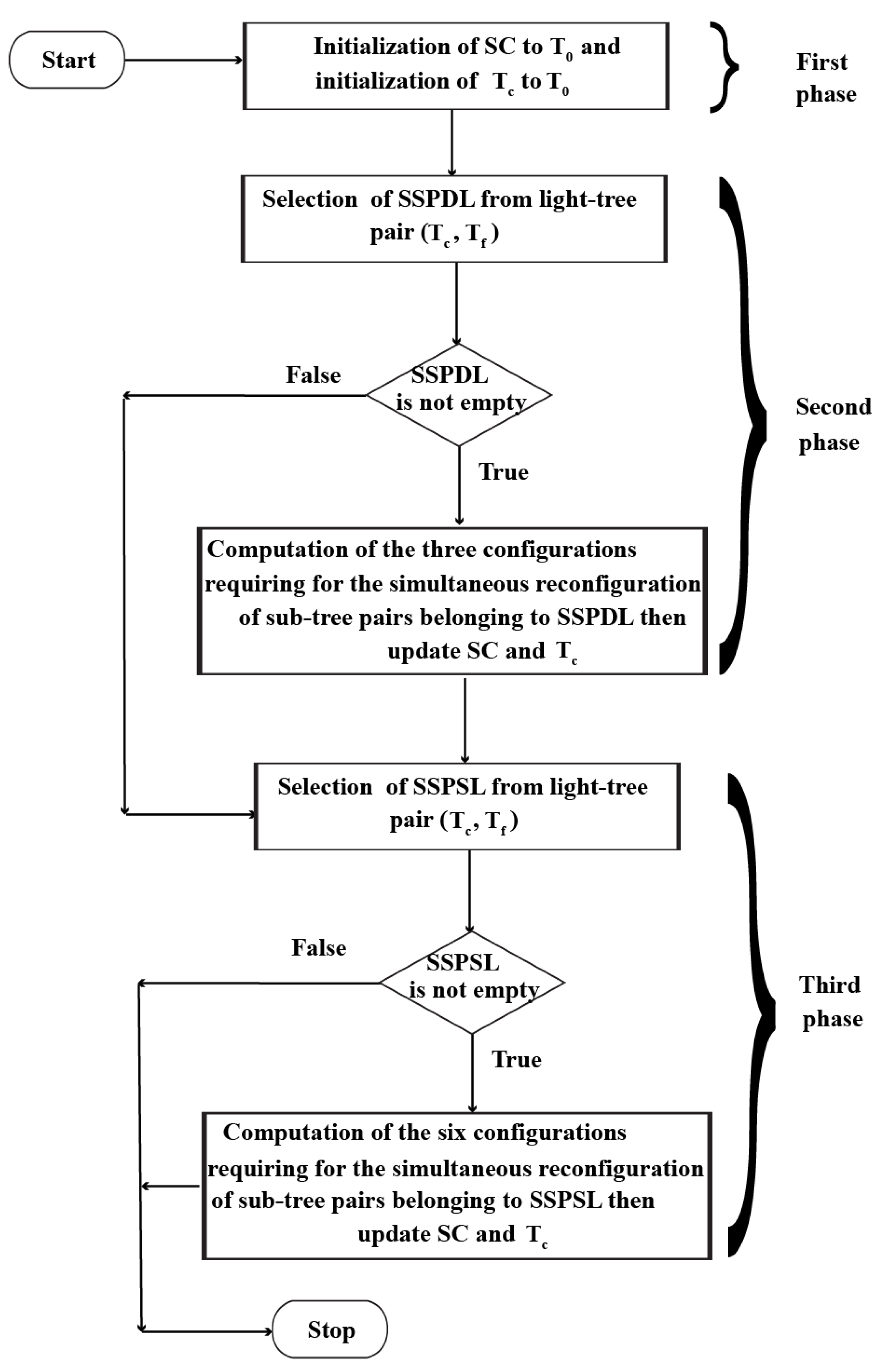
LRASRS is a three-phase process used to progressively build the sequence of configurations SC. The first phase takes the initial light-tree T 0 as the first element of the sequence of configurations. Then, the second phase selects the set of sub-tree pairs with disjointed links (refer to line 3). If this set of sub-tree pairs with disjointed links is not empty, then we apply on them the three reconfiguration primitives (refer to lines 7, 8, and 9) to compute the three configurations (to be appended to S C ) required to reconfigure the set of sub-tree pairs with disjointed links simultaneously. During the third phase, the set of sub-tree pairs with shared links is selected. If this set of sub-tree pairs with shared links is not empty, then we apply the three reconfiguration primitives on them twice (refer to lines 15 and 17) to compute the six configurations (to be appended to S C ) required to reconfigure simultaneously the set of sub-tree pairs with shared links. Figure 5 presents a flowchart to summarize the explanation of Algorithm 1 gives here.
According to lines 7, 8, and 9, a new configuration is obtained by adding or deleting some established wavelength channels to the current configuration. Moreover, these established wavelength channels may concern either sub-tree pairs with disjointed links or sub-tree pairs with shared links. In the former case, a new configuration does not use a spare wavelength because a sub-tree pair with disjointed links does not require the use of a spare wavelength, according to Section 4.1.1  ( i ) . In the latter case, a new configuration uses a spare wavelength because a sub-tree pair with shared links require a spare wavelength. However, according to Section 4.1.2, a sub-tree pair with shared links requires the use of a spare wavelength as few times as possible ( i i ) . From ( i ) and ( i i ) , it results that the sequence of configurations S C minimizes the cost of spare wavelengths ( i i i ) . In addition, based on the last paragraph of Section 4.2, each configuration is required for the simultaneous reconfiguration of a set of sub-tree pairs. Therefore, Algorithm 1 builds a short sequence of configurations ( i v ) . Moreover, each sub-tree pair (with disjointed links or with shared links) has the property of non-interruption of the flow according to Section 4.1 ( v ) . Furthermore, Algorithm 1 stops ( v i ) . Therefore, ( i i i ) , ( i v ) , ( v ) , and ( v i ) prove the total correctness of Algorithm 1.
Algorithm 1 Light-tree pair reconfiguration algorithm by simultaneous reconfiguration of sub-tree pairs (LRASRS).
Input:T0, Tf                     // T0: The initial light-tree; Tf: The final light-tree
Onput:SC                           // Sequence (or list) of configurations
 1: T c = T 0 ; C u r _ C = T c ; S C = C u r _ C                      // F irst phase
 2: ω 0 = W a v e l e n g t h T 0
                              // Start of second phase
 3: S T _ p a i r s = set of sub-tree pairs with disjointed links from T c , T f    //  S T _ p a i r s = { S T c 1 , S T f 1 , , S T c k , S T f k }
 4: if S T _ p a i r s is not null then
 5:   n e w _ S T s = list of new sub-trees from S T _ p a i r s       //  n e w _ S T s = S T f 1 , , S T f k
 6:   c u r _ S T s = list of current sub-trees from S T _ p a i r s     //  c u r _ S T s = S T c 1 , , S T c k
 7:   C u r _ C = C u r _ C ∪ PREESTAB_SPs n e w _ S T s , ω 0 ; S C . a p p e n d C u r _ C
 8:   C u r _ C = C u r _ C SWITCH c u r _ S T s , n e w _ S T s , ω 0 ; S C . a p p e n d C u r _ C
 9:   C u r _ C = C u r _ C \ DELETE_SPs c u r _ S T s , ω 0 ; S C . a p p e n d C u r _ C
 10:   T c = C u r _ C
 11: end if                                 // End of second phase
 12:  S T _ p a i r s = set of sub-tree pairs with shared links from T c , T f      // Start of third phase
 13: if S T _ p a i r s is not null then
 14:    ω 1 = S p a r e _ W a v e l e n g t h T c , T f
 15:   Run instructions from line 5 to line 10 by replacing ω 0 with ω 1 at lines 7 and 8
 16:    c u r _ S T s = list of new sub-trees from S T _ p a i r s
 17:   Run instructions from line 7 to line 10 by replacing ω 0 with ω 1 only at line 9
 18: end of                                  // End of third phase
 19: Return S C
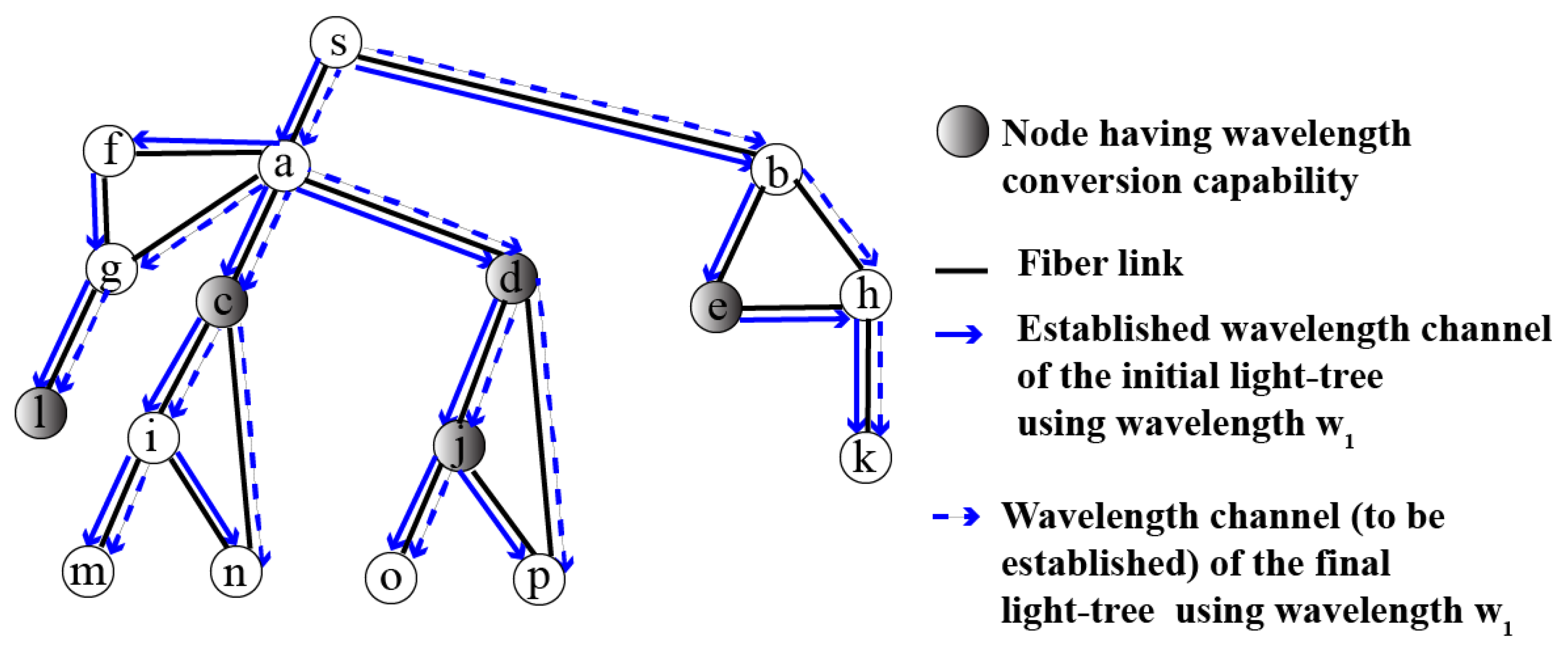
Figure 6 shows a problem instance, which concerns the multicast connection < s , { k , l , m , n , o , p , } > . In Figure 6, the set of links in solid blue forms the initial light-tree T 0 rooted at node s. Furthermore, the set of links in dotted blue forms the final light-tree T f rooted at node s. Figure 7 illustrates the sequence of configurations that is returned by Algorithm 1 for the problem instance.
At the first phase of Algorithm 1, the initial light-tree T 0 is taken as the first element of the sequence of configurations (see Figure 7a) in the first phase. The set of sub-tree pairs with disjointed links is formed by the sub-tree pair with disjointed links ( { a { f { g } } , { a { g } } ) , which is rooted at node a and the sub-tree pair with disjointed links ( { b { e { h } } , { b { h } } ) , which is rooted at node b. Thus, the set of new sub-trees is formed by the sub-tree { a { g } } and the sub-tree { b { h } } . Similarly, the set of current sub-trees is formed by the sub-tree { a { f { g } } } and the sub-tree { b { e { h } } } . Figure 7b–d shows the three configurations (computed by the second phase of Algorithm 1), which concern the sub-tree pairs with disjointed links. Note that these configurations avoid flow interruptions. Indeed, each of these configurations contained a fully configured path between the source node s and each destination node belonging to { k , l , m , n , o , p } . In addition, these configurations do not use a spare wavelength. The set of sub-tree pairs with shared links is formed by the sub-tree pair ( { c { i { m , n } } } , { c { i { m } , n } } ) and the sub-tree pair ( { d { j { o , p } } } , { d { j { o } , p } } ) . Thus, the set of new sub-trees is formed by { c { i { m } , n } } and { d { j { o } , p } } . Furthermore, the set of current sub-trees is formed by { c { i { m , n } } } and { d { j { o , p } } } . The first step (refer to line 15 of Algorithm 1) of the third phase is performed. Figure 7e–g shows the first three configurations that concern the sub-tree pairs with shared links. Next, the second step (refer to line 17 of Algorithm 1) of the third phase computes the last three configurations that concern the sub-tree pairs with shared links. Note also that these configurations avoid flow interruptions. Figure 7h represents the last configuration of these three configurations. This configuration shares all its links with the final light-tree T f . Thus, the sequence of configurations is completed, and it avoids flow interruptions.

5. Simulations

Simulations were conducted to investigate the effectiveness of the proposed method when varying system parameters. The python language was used to implement our method. All simulations were performed on a laptop computer equipped with an Intel Core i5-9300H processor at 2.40 GHz, 8 GB RAM, and a Windows 10 operating system. The criteria evaluated during the simulations and the setting of the simulations are presented in the following subsections.

5.1. Performance Criteria

To determine the effectiveness of the proposed method, we compared our method (i.e., LRASRS) with RCBRwPR and MBB_1. To do this, three criteria were retained: the average rate of flow interruptions (see Equation (2)), the cost of spare wavelengths (see Equation (4)), and the length of the reconfiguration process. The length of the reconfiguration process denoted by n b _ s t e p s S C is the number of steps required by the sequence of configurations SC. This criterion is defined by Equation (5):
n b _ s t e p s S C   =   S C 1

5.2. Simulation Setup

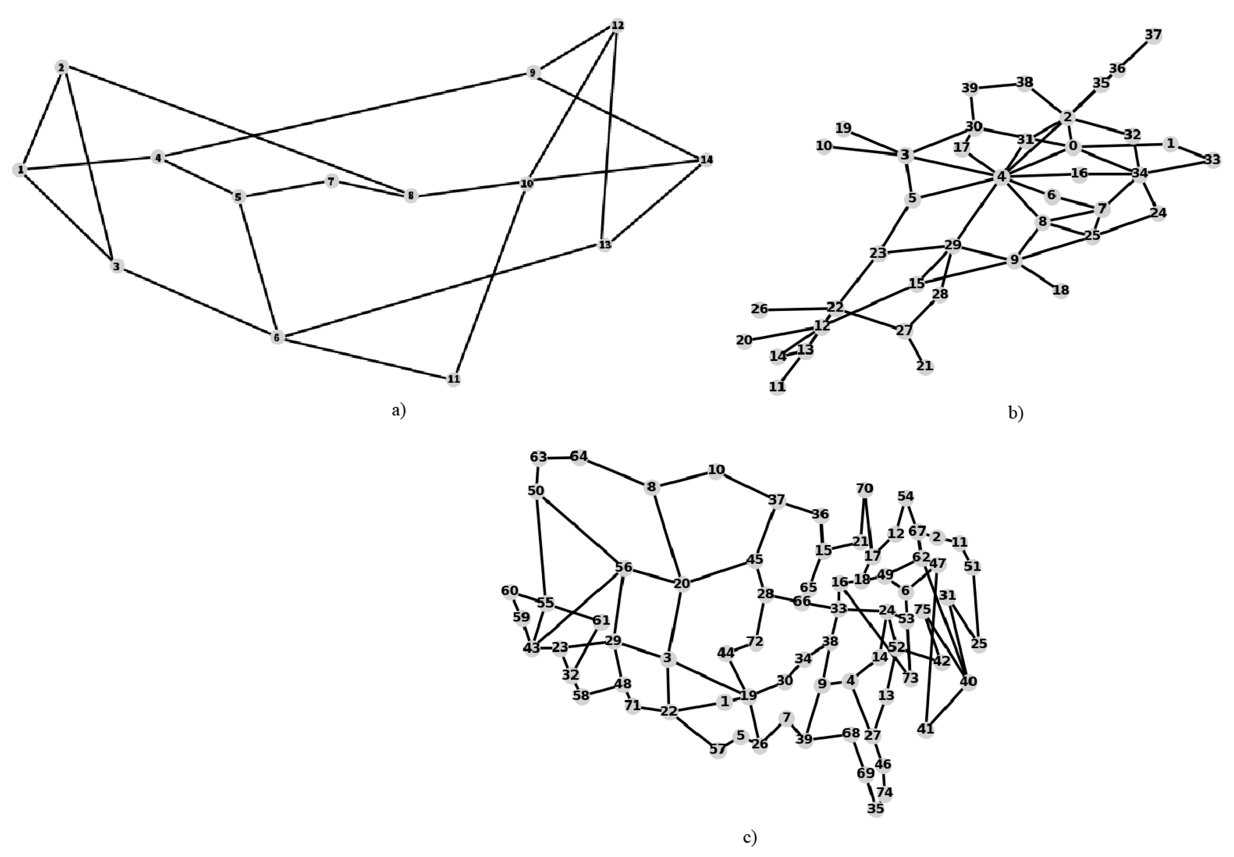
The simulations are based on three realistic network topologies (see Table 1 and Figure 8) widely used in the field of optical network research [25]. These three topologies are NSFNET (small size), GEANT (medium size), and CORONET (large size) [26].
Each topology is represented by a graph G V , E that is implemented using Networkx [27], a python package for graph analysis. V is the number of nodes and E is the number of links. Note that for each topology, the number of nodes that have the wavelength conversion capability V c is selected randomly (uniform law) in [ 1 ; V 2 [ .
For each topology, a simulation was performed. Note that without loss generality, we assume that each link (i.e., optical fiber) supports at most Ω wavelengths ( Ω = 16 ). A simulation consists of performing the following process 5000 times:
  • Randomly select a node, which is taken as the source node of a multicast connection.
  • Randomly select some nodes, which are used as the destination nodes of the multicast connection.
  • The initial tree of the multicast connection is built by generating the tree of the shortest paths that spans the source node and the destination nodes using the Dijkstra algorithm [28].
  • The final tree is built by generating the spanning tree of minimum weight that spans the source and destination nodes using the Prim algorithm [29].
  • Both trees are assigned the same randomly selected wavelength (uniform law) in the set of available wavelengths to obtain the initial light-tree and the final light-tree.
  • The light-tree pair (initial light-tree, final light-tree) is used as an input by three methods: MBB_1, RCBRwPR, and our method (i.e., LRASRS).
At the end of each simulation, we statistically evaluate the performance criteria of the three methods.

6. Results and Discussion

The results (average (AVG), standard deviation (SD), maximum (Max), and minimum (Min)) of the three performance criteria are noted from Table 2, Table 3 and Table 4.
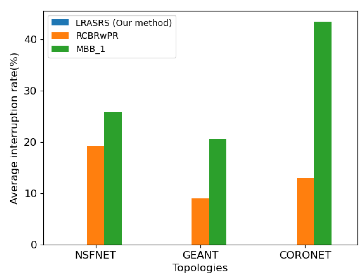
Table 2 shows that our method (i.e., LRASRS) provides an average rate of flow interruptions equal to zero, regardless of a given real topology (NSFNET, GEANT, CORONET). This finding confirms that LRASRS allows light-tree pair reconfiguration without flow interruption in a sparse wavelength converter network. However, Table 2 and Figure 9 show that MBB_1 and RCBRwPR provide a non-zero average rate of flow interruptions (in percent). This is explained by the fact that some instances (of the problem) generated during simulations contained at least one branch pair such that the branches of this pair share links and some switching nodes did not have the wavelength conversion capability useful for the SWITCH function, which is specified at Section 4.3. Thus, these two methods cause some flow interruptions. Note that our method color (i.e., blue) does not appear in Figure 9 because, according to Table 2, our method (i.e., LRASRS) does not generate flow interruptions.
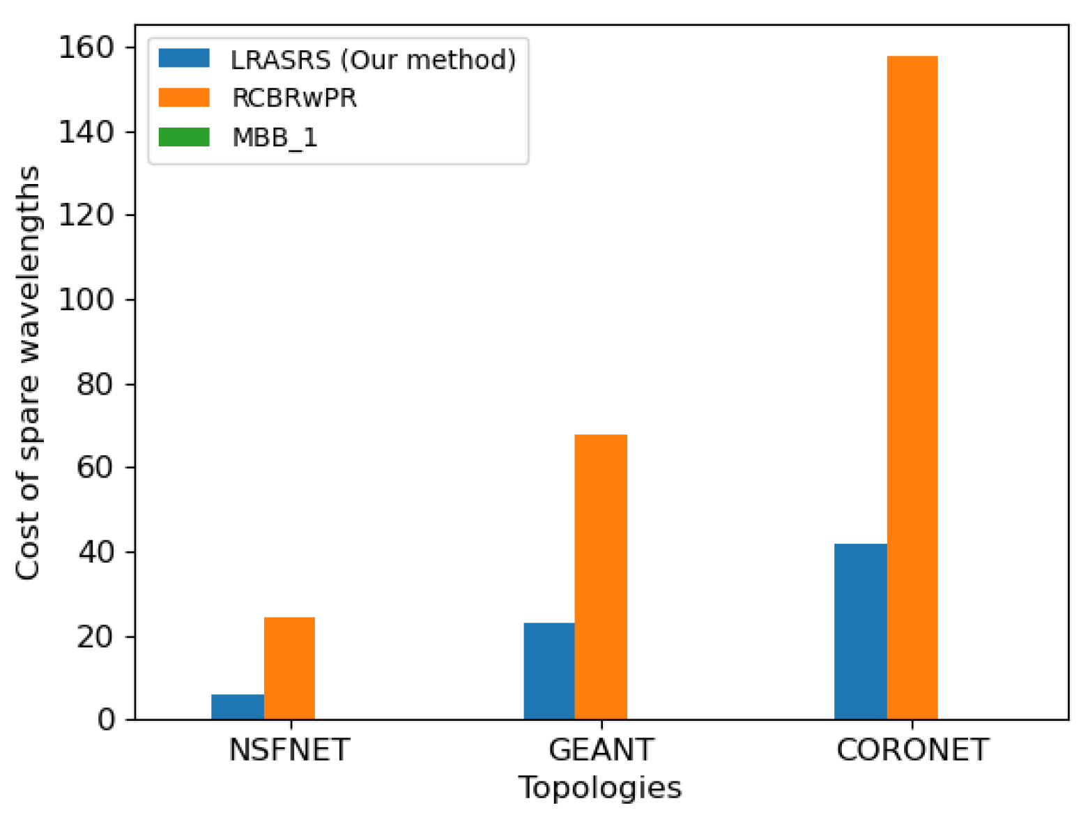
Table 3 shows that RCBRwPR provides the highest cost of spare wavelengths. This is explained by the fact that this method requires the use of a spare wavelength for each branch pair during the reconfiguration process, whereas LRASRS requires the use of a spare wavelength only if some sub-tree pairs with shared links are selected during the reconfiguration process and MBB_1 does not require the use of a spare wavelength. Note that the color that represents MBB_1 (i.e., green) does not appear in Figure 10 because MBB_1 does not require the use of a spare wavelength. Furthermore, Figure 10 and Table 3 show that the cost of spare wavelengths increases with the size of the network (so with the size of light-trees) when we use RCBRwPR or LRASRS. This is normal because, according to Equation (4) and the definition of the cost of spare wavelengths (see Section 3), it is trivial to say that the cost of spare wavelengths is correlated to the size of light-trees and the number of different spare wavelengths used for light-tree pair reconfiguration. In short, simulations confirm that MBB_1 and RCBRwPR are not efficient for a light-tree pair reconfiguration in a sparse wavelength converter network.
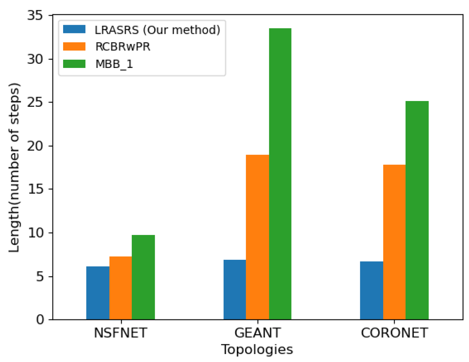
Table 4 and Figure 11 show that MBB_1 causes the greatest number of steps and our method (i.e., LRASRS) causes the lowest number of steps. These findings are explained by the fact that at each reconfiguration step, MBB_1, RCBRwPR, and LRASRS allow, respectively, to reconfigure a single branch pair, to reconfigure a set of branch pairs simultaneously, and to reconfigure a set of sub-tree pairs simultaneously. In addition, it is important to note that the simulation results in Table 4 (refer to Min/Max values) confirm that our method (i.e., LRASRS) uses at least three steps and at most nine steps to solve the problem of a light-tree pair reconfiguration. Therefore, this finding shows that our method has good scalability property.

7. Conclusions

Reconfiguration is an important mechanism used by network operators to optimize network performance. This study focuses on the problem of light-tree pair reconfiguration. Some methods based on a branch approach exist, and they solve this problem if all nodes of the WDM network have wavelength conversion capability. To our knowledge, no method has been proposed to solve this problem if only a small fraction of nodes has wavelength conversion capability.
To fill this lack of solution, we proposed a method based on a sub-tree approach. Our method proposes a sequence of configurations to reconfigure simultaneously a set of sub-tree pairs at each step of the process of a light-tree pair reconfiguration. To do this, we characterize the sub-tree pairs that can be selected from a light-tree pair to be reconfigured. Then we prove that the sub-tree pairs belonging to the same type of sub-tree pair may be reconfigured simultaneously. The simulations confirm that our method allows us to reconfigure a light-tree pair (i.e., an initial light-tree, a final light-tree) without flow interruption, while existing methods generate flow interruptions. Then our method causes the lowest non-zero value of the cost of spare wavelengths. It is important to note that the use of our method for light-tree reconfiguration avoids service disruptions in multicast applications, such as telemedicine and videoconferencing. Thus, network operators do not pay financial penalties to customers that use multicast applications in case of reconfiguration, whereas MBB_1 and RCBRwPR cause flow interruptions, so they are not efficient in solving the formulated problem. In addition, the simulations confirm that our method has a good scalability property: the number of steps of the reconfiguration process scales slowly with the size of the network.
In a sparse wavelength converter network, another good solution to solve the MCRWA problem is semi-light-tree [30]. Therefore, future works should be focused on the problem of a semi-light-tree pair reconfiguration.

Author Contributions

Conceptualization, A.F.A., J.C.A. and S.O.; methodology, A.F.A., J.C.A. and B.C.; implementation, A.F.A.; writing—original draft preparation, A.F.A., J.C.A. and B.C.; writing—review and editing, A.F.A. and J.C.A.; supervision, B.C. All authors have read and agreed to the published version of the manuscript.

Funding

This research received no external funding.

Institutional Review Board Statement

Not applicable.

Informed Consent Statement

Not applicable.

Data Availability Statement

Not applicable.

Conflicts of Interest

The authors declare no conflict of interest.

References

  1. Puche, W.S.; Vesga, J.C.; Sierra, J. Routing and Allocation of Wavelengths in Elastic Optical Networks: A Survey. Indian J. Sci. Technol. 2018, 11, 1–8. [Google Scholar] [CrossRef]
  2. Wu, Q.; Zhou, X.; Wang, J.; Yin, Z.; Lin, L. Multicast routing and wavelength assignment with delay constraint in WDM networks with sparse wavelength conversions. Photonic Netw. Commun. 2009, 19, 144–154. [Google Scholar] [CrossRef]
  3. Iness, J.; Mukherjee, B. Sparse Wavelength Conversion in Wavelength-Routed WDM Optical Networks. Photonic Netw. Commun. 1999, 1, 183–205. [Google Scholar] [CrossRef]
  4. Petale, S.; Jaisingh, T. Optimal of wavelength converter deployment in WDM optical networks. In Proceedings of the 3rd International Conference on Microwave and Photonics (ICMAP), Dhanbad, India, 9–11 February 2018; pp. 1–2. [Google Scholar]
  5. Wu, Y.; Xu, S. An Algorithm for Dynamic Routing and Wavelength Assignment in WDM Network. In Proceedings of the 2016 Joint International Information Technology, Mechanical and Electronic Engineering, Xi’an, China, 4–5 October 2016; pp. 293–299. [Google Scholar]
  6. Zakouni, A.; Toumi, H.; Saidi, A.; Mabrouk, A. Wavelength Assignment Vs. Wavelength Converter Placement in Wavelength-Routed Optical WDM Networks. Procedia Comput. Sci. 2019, 160, 766–771. [Google Scholar] [CrossRef]
  7. Pinto-Roa, D.P.; Brizuela, C.A.; Barán, B. Multi-objective routing and wavelength converter allocation under uncertain traffic. Opt. Switch. Netw. 2015, 16, 1–20. [Google Scholar] [CrossRef]
  8. Cisco Annual Internet Report (2018–2023). Available online: https://www.cisco.com/c/en/us/solutions/collateral/executive-perspectives/annual-internet-report/white-paper-c11-741490.html (accessed on 28 April 2020).
  9. Zhou, F.; Molnar, M.; Cousin, B. Light-hierarchy: The optimal structure for multicast routing in WDM mesh networks. In Proceedings of the 15th IEEE Symposium on Computers and Communications, Riccione, Italia, 22–25 June 2010; pp. 611–616. [Google Scholar]
  10. Le, D.D.; Zhou, F.; Molnár, M. Minimizing Blocking Probability for the Multicast Routing and Wavelength Assignment Problem in WDM Networks: Exact Solutions and Heuristic Algorithms. J. Opt. Commun. Netw. 2015, 7, 36–48. [Google Scholar] [CrossRef]
  11. Zhou, F.; Ait-ouahmed, A.; Cheref, A. QoT-aware multicast provisioning using column generation in mixed-line-rate optical networks. In Proceedings of the 2016 International Conference on Computing, Networking and Communications (ICNC), Kauai, HI, USA, 15–18 February 2016; pp. 1–5. [Google Scholar]
  12. Zhou, F.; Ju, M.; Ait-ouahmed, A. Joint Optimization for Multicast Provisioning in Mixed-Line-Rate Optical Networks With a Column Generation Approach. J. Lightwave Technol. 2018, 36, 637–649. [Google Scholar] [CrossRef]
  13. Barat, S.; Keshri, B.N.; De, T. A Cost Function Based Multi-objective Multicast Communication over WDM Optical Fiber Mesh Network. In Advances in Computer, Communication and Control; Springer: Singapore, 2019; pp. 75–85. [Google Scholar]
  14. Lin, H.C.; Wang, S.W. Splitter placement in all-optical WDM networks. In Proceedings of the IEEE Global Telecommunications Conference, St. Louis, MO, USA, 28 November–2 December 2005. [Google Scholar]
  15. Li, H.; Wu, J. Survey of WDM network reconfiguration: Topology migrations and their impact on service disruptions. Telecommun. Syst. 2015, 60, 349–366. [Google Scholar] [CrossRef]
  16. Chlamtac, I.; Ganz, A.; Karmi, G. Lightpath communications: An approach to high bandwidth optical WAN’s. IEEE Trans. Commun. 1992, 40, 1171–1182. [Google Scholar] [CrossRef] [Green Version]
  17. Wu, J. A survey of WDM network reconfiguration: Strategies and triggering methods. Comput. Netw. 2011, 55, 2622–2645. [Google Scholar] [CrossRef]
  18. Solano, F.; Pióro, M. WDM network re-optimization avoiding costly traffic disruptions. Telecommun. Syst. 2011, 52, 907–918. [Google Scholar] [CrossRef] [Green Version]
  19. Cousin, B.; Adépo, J.C.; Babri, M.; Oumtanaga, S. Tree Reconfiguration without Lightpath Interruption in Wavelength Division Multiplexing Optical Networks with Limited Resources. Int. J. Comput. Sci. Issues 2014, 11, 7–17. [Google Scholar]
  20. Solano, F. Slick Lightpath Reconfiguration Using Spare Resources. J. Opt. Commun. Netw. 2013, 5, 1021–1031. [Google Scholar] [CrossRef]
  21. Cousin, B.; Adépo, J.C.; Oumtanaga, S.; Babri, M. Tree reconfiguration without lightpath interruption in WDM optical networks. Int. J. Internet Protoc. Technol. 2012, 7, 85–95. [Google Scholar] [CrossRef]
  22. Solano, F. Analyzing Two Conflicting Objectives of the WDM Lightpath Reconfiguration Problem. In Proceedings of the IEEE Global Telecommunications Conference, Honolulu, HI, USA, 30 November–4 December 2009; pp. 1–7. [Google Scholar]
  23. Jaumard, B.; Duong, H.Q.; Armolavicius, R.; Morris, T.; Djukic, P. Efficient Real-Time Scalable Make-Before-Break Network Re-Routing. J. Opt. Commun. Netw. 2019, 11, 52–66. [Google Scholar] [CrossRef]
  24. Adépo, J.C.; Aka, B.; Babri, M. Tree Reconfiguration with Network Resources Constraint. Int. J. Comput. Sci. Telecommun. 2016, 7, 1–4. [Google Scholar]
  25. Pavan, C.; Morais, R.M.; da Rocha, J.R.F.; Pinto, A.N. Generating Realistic Optical Transport Network Topologies. J. Opt. Commun. Netw. 2010, 2, 80–90. [Google Scholar] [CrossRef] [Green Version]
  26. The Internet Topology Zoo. Available online: http://www.topology-zoo.org/dataset.html (accessed on 18 December 2020).
  27. Hagberg, A.; Swart, P.; Chult, D.S. Exploring network structure, dynamics, and function using NetworkX. In Proceedings of the 7th Python in Science Conferences, Pasadena, CA, USA, 21 August 2008; pp. 11–15. [Google Scholar]
  28. Dijkstra, E.W. A note on two problems in connexion with graphs. Numer. Math. 1959, 1, 269–271. [Google Scholar] [CrossRef] [Green Version]
  29. Prim, R.C. Shortest Connection Networks And Some Generalizations. Bell Syst. Tech. J. 1957, 36, 1389–1401. [Google Scholar] [CrossRef]
  30. Shuai, T.; Ai, W. New algorithms for multicast routing and wavelength assignment in multi-hop optical WDM networks. Photonic Netw. Commun. 2011, 23, 53–59. [Google Scholar] [CrossRef]
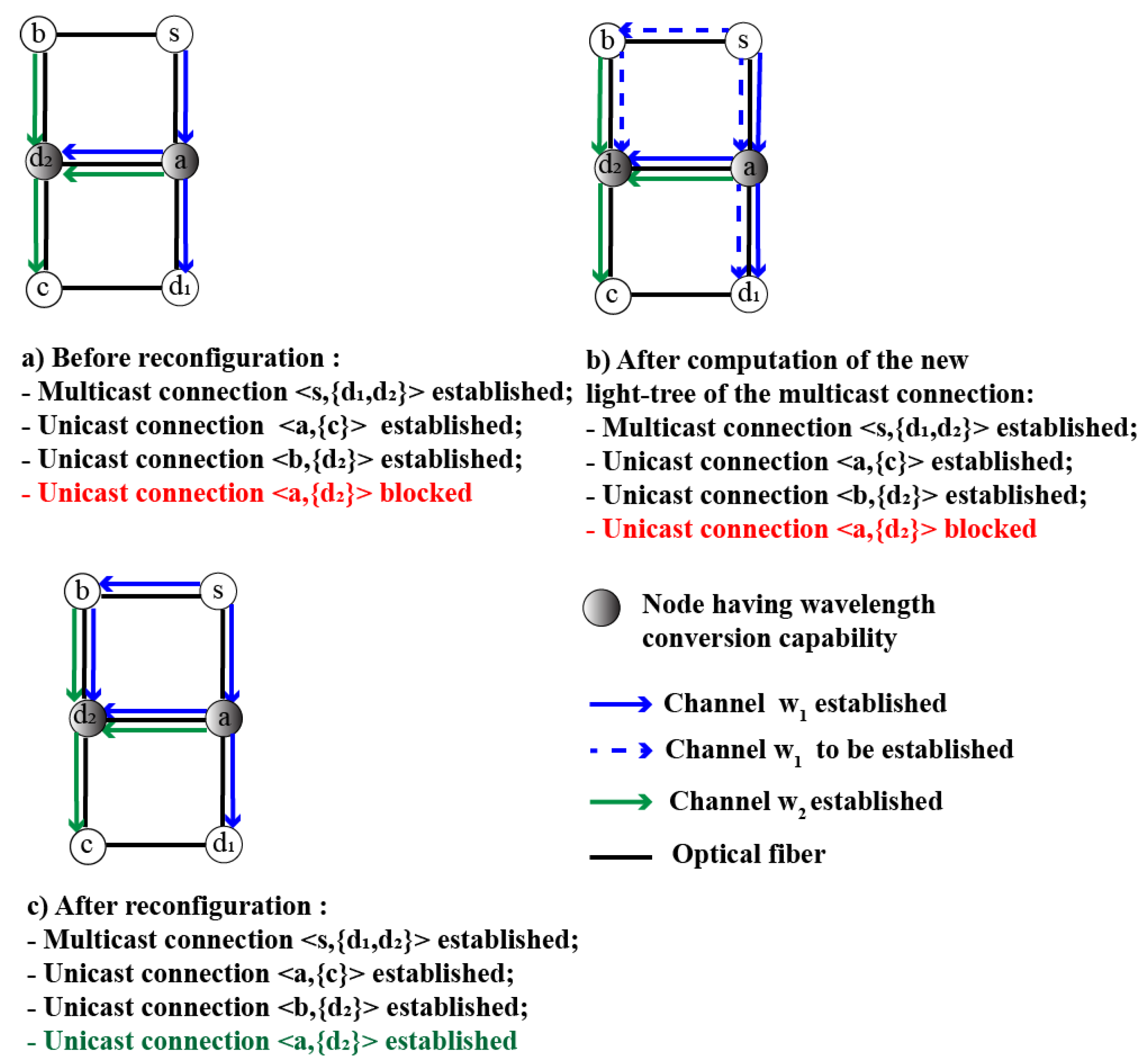
Figure 1. Illustration of reconfiguration benefit.
Information 12 00211 g001
Figure 2. Illustration of a sequence of configurations returned by MBB_1.
Information 12 00211 g002
Figure 3. Illustration of a sequence of configurations returned by BpBAR_2.
Information 12 00211 g003
Figure 4. Instance of light-tree pair containing each kind of sub-tree pair.
Information 12 00211 g004
Figure 5. Flowchart of our method (i.e., Algorithm 1); SSPDL = set of sub-tree pairs with disjointed links; SSPSL = set of sub-tree pairs with shared links.
Information 12 00211 g005
Figure 6. Instance of problem.
Information 12 00211 g006
Figure 7. A view of the execution of the configuration sequence returned by our method.
Information 12 00211 g007
Figure 8. Network topologies: (a) 14-node NSFNET; (b) 40-node GEANT; (c) 75-node CORONET.
Information 12 00211 g008
Figure 9. Comparison of the average rate of flow interruptions.
Information 12 00211 g009
Figure 10. Comparison of the cost of spare wavelengths.
Information 12 00211 g010
Figure 11. Comparison of the number of steps.
Information 12 00211 g011
Table 1. Topology information.
NetworkNum. of NodesNum. of Links
NSFNET1421
GEANT4075
CORONET7599
Table 2. Average rate of flow interruptions (%) caused by the three methods.
MethodsNSFNETGEANTCORONET
AVGSDm/MAVGSDm/MAVGSDm/M
LRASRS000/0000/0000/0
RCBRwPR19.2522.540/669.099.380/7712.9812.950/78
MBB_125.9016.282/8320.6913.950/9443.4821.471/96
Table 3. Cost of spare wavelengths caused by the three methods.
MethodsNSFNETGEANTCORONET
AVGSDm/MAVGSDm/MAVGSDm/M
LRASRS6.064.460/2022.8713.480/7341.9219.860/93
RCBRwPR24.1910.496/4867.6455.074/264157.7694.418/434
MBB_1000/0000/0000/0
Table 4. Length (i.e., number of steps) caused by the three methods.
MethodsNSFNETGEANTCORONET
AVGSDm/MAVGSDm/MAVGSDm/M
LRASRS6.112.213/96.871.913/96.681.413/9
RCBRwPR7.253.063/1418.9813.153/5917.798.913/35
MBB_19.753.586/2133.4815.136/6325.1112.726/60
Publisher’s Note: MDPI stays neutral with regard to jurisdictional claims in published maps and institutional affiliations.