1. Introduction
Industry 4.0 is considered the fourth industrial revolution. It follows the arrival of production automation [
1]. The concept of Industry 4.0 emerged at the beginning of the 21st century. Kagermarin et al. [
2] refer to the digitization of production and describe the vision of an intelligent factory, characterized by the networking of all production processes in order to operate interactively and to increase productivity and efficiency in the use of resources. Companies are facing increasing competition in their markets, leading managers to constantly seek new methods, approaches, and strategies to improve operational flexibility, efficiency, innovation, and responsiveness through an accurate control supported by 4.0 technologies [
3,
4]. The use of digital approaches anticipates the development and control of intelligent production systems by contributing, for example, to the control of production flow’s behavior.
In the context of Industry 4.0, the need for modeling and simulation (M&S) becomes more and more important as it allows users to manipulate virtual prototypes to easily reproduce experiments in different situations while working on accessible virtual models [
5]. This approach to modeling and simulation relates to the four pillars of Industry 4.0: (1) Digitization: the interconnection of systems and the management of large amounts of data allow the enrichment of a model’s input data; (2) Flexibility: the simulation of an industrial process allows an efficient representation and analysis of its operations. This results in an increased ability to make decisions and adapt to its environment; (3) Logistic tools: An M&S tool can be connected to an information system as a decision support module; and (4) Human–machine interface: as in all operations involving human and machine resources, the need for efficiency and ease of use are necessary.
The Industry 4.0 business models rely on data to control processes. The collected and predicted data help in analyzing and understanding complex systems and facilitate the control of their operation. The ability to virtualize workspaces or systems bridges the gap between the physical world driven by machines and the virtual world. According to Madni et al. [
6], the digital twin (DT) creates the ideal environment for data collection on all aspects of the manufacturing process for analysis and simulation. When data are accurately collected and a digital twin is designed, systems integrators, data analysts, and others can use it to drive business policies and improve decision-making processes. According to Mangles [
7], by 2021, nearly half of the large industrial companies will use DT to assess the technical performance and risks of their systems. However, as systems become larger and more complex, the difficulty of simulating these systems and their associated risks increases proportionately. As stated by Taylor et al. [
8], when the model is complex and requires high-performance resources, the classical simulation approach becomes insufficient. The model execution must be divided and distributed among a large number of processors or machines, based on appropriate modeling tools. Therefore, distributed simulation (DS) becomes essential: one simulation is divided into multiple subsimulations (or models) of a complex system. Each autonomous simulation can be executed on a different computer and sometimes on a different LAN (local area network). From a general point of view, this solution divides the complex problems into simpler subproblems, but also raises interoperability issues.
The model we propose in this project takes into consideration the notion of complexity distribution and risk management. Thus, we propose the association of three main contributions:
First, the interoperability between heterogeneous simulation components to allow component reuse, load balancing between separate components, and reduction of development costs. High-level architecture (HLA) and functional mockup interface (FMI) are both standards for distributed simulation providing interfaces to solve interoperability issues between tools and simulations. Creating a bridge between these two standards allows us to connect components from several different domains. The bridging tool used to interconnect these two standards is Papyrus [
9], an open-source modeling and simulation tool;
Second, throughout its lifecycle, every project is subject to numerous internal or external risks and hazards. The management of these risks is critical for the success of the project. In this project, the process and risk are both modeled and taken into consideration. The data input of a simulation is divided into two main parts. On the one hand is an industrial process model with its input data set. On the other hand is a model describing the risks and hazards affecting the simulated process;
Third, an orchestrator component that manages the interconnected distributed simulations. Moreover, a model describing the business process is developed. This model refers to the subcomponents that represent the functional or technical processes.
The rest of this article is structured as follows: A literature review section analyzes the state of the art. The next section shows the materials and methods used to develop the distributed-simulation system.
Section 4 and
Section 5 explain the development steps and mechanisms. The risk-management implementation is detailed in
Section 6.
Section 7 describes the case study and the simulation results. The last section is the conclusion and perspective that presents the general outcome of the work.
2. Literature Review
The industrial processes of complex systems require a method and a framework to interconnect a set of heterogeneous components operating on different platforms and operating systems [
10]. Manufacturing modeling and simulation systems are built from the set of processes, the set of exchanged data, the interconnection of services, and the collaboration between supply chain processes. Therefore, it requires a modeling language to capture all the elements of the system. Then, at the time of execution, a synchronization of the data exchange is necessary. Moreover, the interoperability between components is required during the simulation run. The literature details interesting contributions to enterprise modeling, interoperability, and distributed-simulation standards. These areas are recalled in the following section.
In [
11], Falcone et al. propose the use of the business process management and notation (BPMN) standard to model and better understand the internal mechanisms of the standard. Their approach is divided into two parts: the first aims to use the standard to model the internal functioning mechanisms of a federation; the second aims to use the standard to model the different phases of the whole HLA federation life cycle. In [
12] and [
13], the authors present a collaborative framework based on business process management and notation (BPMN) as well as a middleware that implements the functionalities of BPMN by using basic functions of the HLA standard. BPMN enables the definition and simulation of workflow engines using HLA. Taylor et al. [
14] presented a proposal that improves a commercial simulation tool (commercial-off-the-shelf simulation packages (CSPs)) using distributed-simulation standards. The authors describe the communication between existing business process models (modeled in BPMN) through a network of HLA federates.
Bocciarelli et al. [
15] presented a method for the automated transformation of BPMN processes into EQN (extended queuing network) models. The EQN models are then run as distributed simulations in an e-commerce scenario. This research converts the BPMN into executable code. Bazoun et al. [
16] presented a tool called “SLMToolBOX”. This developed tool is a graphical modeler, a model transformer, and a simulation engine capable of converting a BPMN diagram into DEVS models to simulate the behavior of a process. The DEVS models can be transformed and executed as components of an HLA federation [
17]. Ultimately, Lee [
10] developed a workflow simulation system that combines both BPMN and HLA functionalities. This system allows experts to describe an industrial system in the form of BPMN diagrams. The resulting model will be converted into a set of HLA components that will be simulated using HLA–BPMN middleware.
After the above analysis, some limits can be identified. According to the HLA standard, federation members are autonomous. In a reusability approach, federation members should be reworked (redefine the structure, code, parameters, exchange protocols, etc.), which can be problematic in an environment with high component reuse. In the literature, some articles have already highlighted the benefits that a graphical modeling language would bring to the HLA standard. Despite this observation, we note that few studies have attempted to use a graphical language to orchestrate a distributed HLA simulation. Representing the federate execution sequence and their interactions by a graphical language would increase the potential for reusability and modularity of the standard. The above studies make it possible to use various methods to run distributed workflow languages such as BPMN via the HLA standard. Some studies use the graphical standards, such as BPMN, to represent the internal mechanisms and the interaction of the HLA simulation components. However, one can notice the need of a graphical model that orchestrates and manages a distributed simulation.
In state of the art, various authors have attempted approaches to reduce or resolve interoperability problems specific to the cosimulation standard, in particular FMI. Some are attempting to create linkages between the FMI and HLA, such as Yilmaz et al. [
18] who presented in their paper a method to automatically generate an FMU (functional mockup units) entity able to join an HLA federation as member. A wrapper reads the FMU specification and generates the HLA layer. To demonstrate the FMUFd (FMU-federate) usage, authors developed a simple DS example with MAK HLA Run Time Infrastructure (RTI). In this paper, time synchronization between the two standards (FMI & HLA) is solved by updating the federate time at each running step of the FMU model.
Falcone et al. [
19] presented an integrated way to merge the functional mockup interface (FMI) and the IEEE 1516—High Level Architecture standard. The authors propose two approaches in order to merge the standards. The first approach is an adapter-based approach where a hybrid federate is created. The federate contains an FMU (the behavior of the component to simulate and its solver) coupled with an adapter managing all interactions between HLA-RTI and the FMU component. The second approach is a mediator-based approach where a set of FMUs, an HLA federate that can use FMU to simulate a specific component, and a mediator layer are created in order to coordinate the behavior of the whole system.
Awais et al. [
20] proposed how the strengths of both the HLA and the FMIs can be utilized to realize a distributed hybrid simulation platform. Two different algorithms were proposed. To demonstrate the correctness of algorithms and their performance comparison, a simulation example was chosen from the domain of complex energy systems.
Most risk-management tools are derived from formal methods such as: Obeng, risk checklist, brainstorming [
21], ISSRM, and influence diagrams [
22]. They are frequently implemented in serious games in order to make users aware of the raised problems. Pontakorn et al. [
23] presented a serious game that helps to simulate risk management in software engineering. During the simulation, the participants followed the principles of risk management and aimed to achieve their objectives while saving their expenses. In addition, Jurjens et al. [
24] observed that security problems often arise during the definition of the business processes. It was on the basis of this observation that Olga Altuhhova et al. [
25] stated how security concerns are neglected in business modeling processes, specifically in the modeling information systems. In [
25], the objective was to use the BPMN standard to model the security of business processes and to suggest extensions to the language convergence toward security risk management. In order to achieve the above, authors selected the IS security risk management (ISSRM) domain model and aligned it semantically with the BPMN standard through the development of a dedicated extension. Ralf Laue et al. [
26] presented an evaluation of the business process simulation standard (BPSIM) specification. For simulation purposes, a model must contain a certain amount of information (tasks, resource management, start and end events, etc.) [
24]. The BPSIM standard [
27] is an extension of the BPMN language for process simulation. In BPSIM, parameters are added to an XML file to allow the simulation of the BPMN process. Ralf Laue et al. precised that the language allows modeling independently of simulation tools; however, in practical tests they find that some tools that offer an implementation of the standard only implement a subset of the standard. In addition, some implementations provide useful but proprietary extensions. Since the specification is relatively recent, user interface problems appear (such as the need to go through the editing of text files to simulate certain resources). The authors also point out that BPSIM does not grant an accurate description of resources as usually achieved in traditional simulation tools.
In [
28], Fan et al. focused on ecological risk assessment using a probabilistic approach to characterize risk and deal with uncertainty using Monte Carlo simulations. This simulation relies on data from the American army to evaluate the probabilistic distributions of risk parameters related to the exposure to depleted uranium. Haiyi Lu [
29] developed a tool designed to study UML models that deal with environmental risks. In [
30], Bixio et al. presented the case of the Belgian wastewater treatment plants which faced many hazards during a structure renovation process. The article of Bixio et al. describes a method that combines a probabilistic (Monte Carlo) simulation with deterministic simulations. Originating from the IO-SUIT prototypes [
31] and Pro-(R)isk [
32], the RIO-Suit tool inherits a modular architecture. Common to several research projects, the tool supports risk management and interoperability within collaborative organizations (RIOs). Via a module that manages different situations, the user can declare the model of a collaborative system in the form of graphs (Neo4J) that include a set of objectives related to the collaboration between organizations [
33].
In a high-risk context, uncertainties must be taken into account from the early stages of the modeling process—the sooner, the better to avoid unwanted events. Taking into account risk management in simulation involves two difficulties:
Adding a representation of risks with their parameters (impacts, occurrences, probabilities, and side effects) to a system drastically increases the difficulty of the modeling process. Due to this complexity, some authors propose the outsourcing of the hazards. However, the model will no longer be autonomous. Thus, the user will not be able to test a risk-free scenario;
Simulating a global system implies access and communication with all the subsystems. In the majority of cases, the different subsystems are from vast and varied domains. Therefore, there is a significant problem of the components’ homogeneity.
In the sections below, we provide methods and solutions to the above-mentioned difficulties faced by the engineers. We propose a method separating the input data from the risk-management parameters. Risk parameters are linked to a user-configurable database that may or may not be connected to the main model. This database can be updated during the simulation run. Moreover, distributed-simulation standards (HLA and FMI) are used to solve the heterogeneity issue.
4. Distributed-Simulation Orchestration
According to the HLA standard [
37], a federation cannot be managed from a component since each federate is autonomous and cannot be controlled. Moreover, there is no graphical tool allowing the implementation of a distributed-simulation scenario that defines an order of execution for different simulations constituting an HLA federation. This point is an important aspect since it would allow the distributed-simulation behavior to be defined using a simple graphical-modeling language.
Defining a simulation scenario means centralizing the information that decides the order of execution of the different distributed simulations. The concept of “order of execution” introduces the notion of pending federates. The main objective is to connect the federates to a specific federation, execute them, and wait for their respective orders in order to launch their simulations appropriately. This diagram must therefore have priority over all the federates of a federation, and this is currently impossible in the HLA standard as described by the HLA specifications. Each federate is autonomous and can only be prioritized by the order of the messages exchanged. This is why a distributed HLA simulation orchestration has never been proposed before.
In order to set up a distributed-simulation scripting system, it is imperative to implement a decision-maker/master mechanism. The decision maker having, as a resource, a graphical diagram describing the execution order of the federates must be able to drive and control the federates described by the model. At this point, the concept of control is interpreted by a set of pre-established rules that will allow the communication between the master and the different federate entities (the slaves) through HLA interactions.
According to the HLA standard, a master federate piloting other federates is not an existing concept in the standard because a federate is an autonomous simulation, which only needs a Run Time Infrastructure (RTI) to work. In the following part, we will describe the development process of an HLA standard upper layer to implement the decision-maker/master mechanism.
7. Simulation Case Study and Results
These researches and proposition were supported by industrial context. At the crossroads of several disciplines, ALSOLENTECH expresses the need for a tool capable of grouping simulation standards, simplifying process modeling by outsourcing risks, and connecting external tools of its environment. In this section, we group together all of the contributions mentioned above to form a global application for the unification of tools and technologies. Papyrus, the orchestration tool, interconnects blocks of functionality, each representing a part of the production process.
ALSOLENTECH is a French company for the design, construction, and operation of the thermodynamic and photovoltaic solar power plants. Based on Fresnel mirrors, the power plant technology proposed makes it possible to supply isolated areas simultaneously with electricity, drinking water, refrigeration, and industrial heat. The technical and economic context of concentrated heat-energy production is a relatively young field of research, which is confronted with notions of uncertainty and competitiveness. This creates a need for risk management. Moreover, our industrial context is a grouping of various fields and technologies, whose intersection allows one to ensure the development and the operation of the solar power plants. All the actors of the industrial chain include tools and knowledge that will need to communicate, without a standardized exchange interface. This need involves issues of interoperability between heterogeneous components, which are addressed by distributed-simulation concepts: each component represents a domain, which is a subpart of a global system to experiment and analyze the performance of the whole system.
In this context, ALSOLENTECH needs to model the process of setting up and deploying a solar-panels field.
Figure 11 shows the process of setting up a solar field. It consists of a set of tasks referring to external tools.
The first step of this model corresponds to the simulation of the materials supply necessary for the different constructions that make up the entire power plant. Then, a set of tasks are launched in parallel:
the delivery of materials necessary for the operation of the solar power plant: raw materials;
the construction of the three structures for the power plant: civil engineering (GC) 1, 2, and 3;
the delivery of the mobile factory to the production site: mobile factory carrying.
Once the mobile factory has been delivered to the production site, and civil engineering 3 (GC3) has been completed, the deployment and operation of the plant can be simulated: “MB Deployment” which simulates the deployment of the plant. Once the solar fields have been deployed, a test battery is carried out to determine the effective power of the plant: “Test mobile factory production”. Then, the solar panels are turned on for testing purposes before delivery.
The first task (“Appro” task in
Figure 11) consists in the supply delivery by airplane of two categories of products. This task is subject to risks and will be deported to a JaamSim simulation. We therefore have two profiles applied to this UML action:
The task ID is transmitted to the Excel file via the ID field in the FailureProfile -> SiteExploitation. The HLAprofile is also applied to it, which points to the name of the federate to be executed -> Appro. As this task is subject to risks, Papyrus queries the environmental risk-management tool, in order to influence the input parameters of the JaamSim simulation. Parameters are calculated and then transmitted to the JaamSim federate by modifying the HLA object visible in
Figure 12.
Here, all parameters are user-configured variables. These are the nominal parameters of the simulation which do not take into account the risk. All these values are modified by the risk-management tool through Moka engine. In a second step, Papyrus sends an execution order interaction to the federate that runs the simulation visible in
Figure 13. The supply delivery simulation is done with an industrial modeling and simulation tool: JaamSim. JaamSim process generating two types of entities (H_Priority and L_Priority). Their number and production rate are input variables. Moreover, the different execution times related to transport, trans-shipment, loading, and unloading are also input parameters (
Figure 12) that can be modified by the risk-management tools. During this simulation, the various performance indicators are recorded and updated at the RTI for each crossing of several blocks in
Figure 13. These parameters (
Figure 12) are updated using the RTI ambassador’s updateAttributeValues() function.
The next steps of the Papyrus process (
Figure 11) are executed in parallel:
The delivery of raw materials for the solar field, and construction steps (raw materials, GC1, GC2, GC3) are tasks simulated by Papyrus and disrupted by the industrial risk-management database;
The delivery of a mobile factory is simulated by Papyrus and disrupted by the environmental risk-management tool. This external component is a system composed of different states performing meteorological queries in order to disrupt the progress of a task. In our case, this is the first time that a Papyrus task uses the FMU. It is therefore in its initial state: queries on the humidity rate (precipitation) of a geographical area for a time described in the configuration file of the simulation.
The next task of the orchestration model concerns the deployment of the power plant. Here, Papyrus once again relocates the complexity of the simulation through a JaamSim model impacted by industrial risks. The “Mobile factory deployment” of
Figure 11 is thus extended by the HLAProfile (which indicates the name of the JaamSim federate to be executed) and the FailureProfile (which introduces hazards in the simulator inputs).
The deployment of the power plant is a task simulated by JaamSim. It involves building and deploying the solar reflectors directly on the production site. Its operation (illustrated in
Figure 14) is a succession of steps transforming steel sheets into mirrors placed on motorized gantries.
As for the previous JaamSim simulation, all production lead times are input parameters of the simulation. Defined by default in the Papyrus configuration file, they are accessible for modification by the industrial risk-management tool. When the task is executed, Papyrus transmits the parameters through an HLA object and sends an execution order interaction.
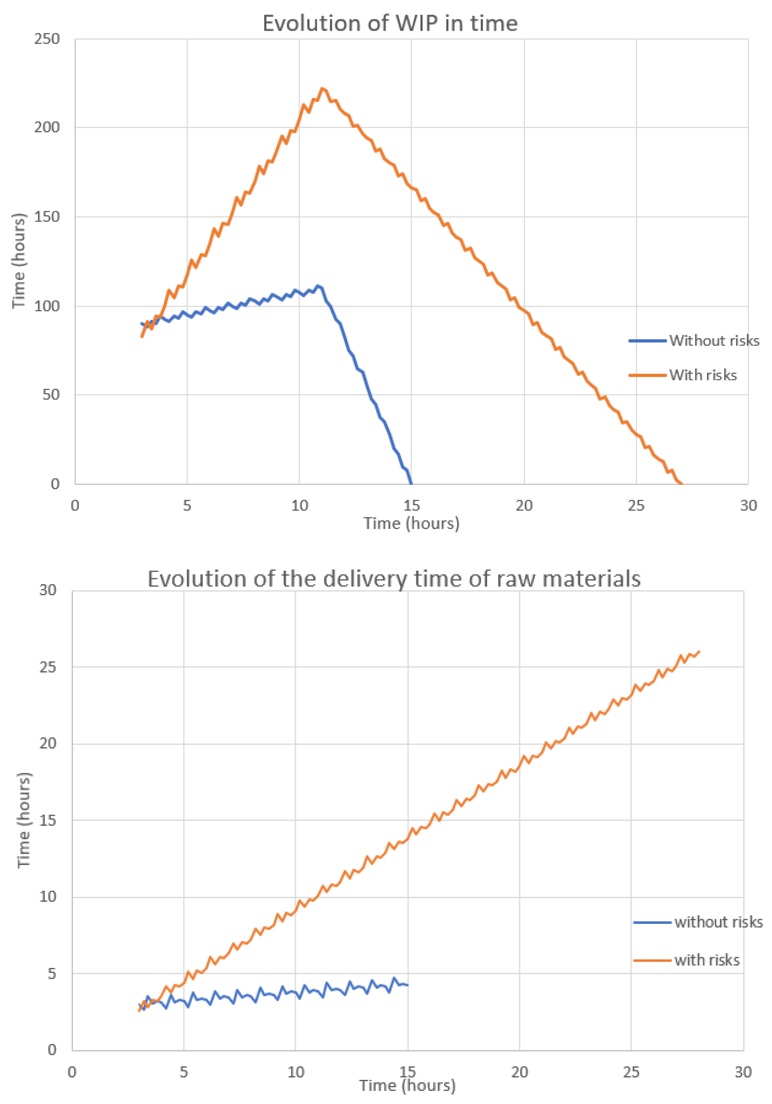
Both JaamSim simulations were configured to trace two KPI’s at simulation runtime:
As a demonstration of efficiency of our proposition, we ran the same simulation two times: first with the risk-management tool enabled and then without the risk-management tool. We can observe these results in
Figure 15.
Papyrus is a modeling and simulation tool that can work autonomously. By default, the orchestration of
Figure 11 can be run without the risk-management extension. Each of the tasks in the model (with the exception of the tasks referring to JaamSim simulations) has a nominal duration defined by the user. The set of these durations is determined by the engineers who estimate the average time of each steps. The uppers graphs of
Figure 15 are results of each JaamSim simulations without risk management enabled. We can see that the delivery time of raw materials without risk management (bottom blue) is linear and is almost horizontal. Once risk management is activated (bottom red), we can see that WIP is degraded. The same observation can be done on the second JaamSim simulation KIP’s (top graph of
Figure 15). All Papyrus tasks have thus received a temporal degradation according to various factors:
semirandom laws described according to the company’s knowledge (reproducible with a seed generation system);
simulation dates;
environmental factors related to the project (location, planned date of the construction site, rainfall, sunshine, etc.);
Author Contributions
Conceptualization, S.G., J.P., G.Z., N.P., and Y.D.; methodology, S.G., J.P., G.Z., N.P., and Y.D.; software, S.G., J.P., and G.Z.; validation, S.G., J.P., G.Z., N.P., and Y.D.; formal analysis, S.G., J.P., G.Z., and Y.D.; investigation, S.G., J.P., G.Z., and Y.D.; resources, S.G., J.P., G.Z., and Y.D.; data curation, S.G. and J.P.; writing—original draft preparation, S.G., J.P., G.Z., and Y.D.; writing—review and editing, S.G., J.P., G.Z., and Y.D.; visualization, S.G. and J.P.; supervision, G.Z. and Y.D.; project administration, G.Z.; funding acquisition, G.Z. and N.P. All authors have read and agreed to the published version of the manuscript.
Funding
This research was partially funded by Region Nouvelle Aquitaine, grant number 2016-1R60102-00007447.
Acknowledgments
Authors acknowledge ALSOLENTECH and CEA TECH for their technical support and their help in using Papyrus and Moka.
Conflicts of Interest
The authors declare no conflict of interest.
References
- Industry 4.0: Definition and Implementation to the Connected Plant. Visiativ Solutions. Available online: https://www.visiativ-solutions.fr/industrie-4-0/ (accessed on 25 September 2020).
- Kagermann, H.; Lukas, W.D.; Wahlster, W. Industrie 4.0: Mit dem Internet der Dinge auf dem Weg zur 4. industriellen Revolution. VDI Nachr. 2011, 13, 2–3. [Google Scholar]
- Adamik, A.; Nowicki, M. Preparedness of Companies for Digital Transformation and Creating A Competitive Advantage in the Age of Industry 4.0. In Proceedings of the International Conference on Business Excellence, Bucharest, Romania, 18–19 March 2018; Sciendo: Lodz, Poland, 2018; Volume 12, pp. 10–24. [Google Scholar]
- Ericson, Å.; Lugnet, J.; Solvang, W.D.; Kaartinen, H.; Wenngren, J. Challenges of Industry 4.0 in SME businesses. In Proceedings of the 2020 3rd International Symposium on Small-Scale Intelligent Manufacturing Systems (SIMS), Kyoto, Japan, 10–12 June 2020; pp. 1–6. [Google Scholar] [CrossRef]
- Ghadge, A.; Er Kara, M.; Moradlou, H.; Goswami, M. The impact of Industry 4.0 implementation on supply chains. J. Manuf. Technol. Manag. 2020, 31, 669–686. [Google Scholar] [CrossRef]
- Madni, A.M.; Madni, C.C.; Lucero, S.D. Leveraging digital twin technology in model-based systems engineering. Systems 2019, 7, 7. [Google Scholar] [CrossRef]
- Mangles, C. Gartner Hype Cycle 2018—Most Emerging Technologies Are 5–10 Years Away. Available online: https://www.smartinsights.com/managing-digital-marketing/managing-marketing-technology/gartner-hype-cycle-2018-most-emerging-technologies-are-5-10-years-away/2018 (accessed on 3 September 2016).
- Taylor, S.J.E. Distributed simulation: State-of-the-art and potential for operational research. Eur. J. Oper. Res. 2019, 273, 1–19. [Google Scholar] [CrossRef]
- Guermazi, S.; Tatibouet, J.; Cuccuru, A.; Dhouib, S.; Gérard, S. Executable Modeling with fUML and Alf in Papyrus: Tooling and Experiments. EXE MoDELS 2015, 11, 3–8. [Google Scholar]
- Lee, D. Development of Mediator-Based Direct Wokrflow Simulation System and HLA/RTI-Based Collaborative BPMS Middleware. Ph.D. Thesis, Korea Advanced Institute of Science and Technology, Daejeon, Korea, 2010. [Google Scholar]
- Falcone, A.; Garro, A.; D’Ambrogio, A.; Giglio, A. Engineering Systems by combining BPMN and HLA-based distributed simulation. In Proceedings of the 2017 IEEE International Systems Engineering Symposium, Vienna, Austria, 11–13 October 2017; pp. 1–6. [Google Scholar]
- Vernadat, F.B. UEML: Towards a Unified Enterprise Modelling Language. In Proceedings of the Actes 3ème Conférence Francophone de Modélisation et Simulation—MOSIM’01, Troyes, France, 25–27 April 2001. [Google Scholar]
- Possik, J.; d’Ambrogio, A.; Zacharewicz, G.; Amrani, A.; Vallespir, B. A BPMN/HLA-Based Methodology for Collaborative Distributed DES. In Proceedings of the 2019 IEEE 28th International Conference on Enabling Technologies: Infrastructure for Collaborative Enterprises (WETICE), Capri, Italy, 12–14 June 2019; IEEE: New York, NY, USA, 2019; pp. 118–123. [Google Scholar]
- Taylor, S.J.E.; Turner, J.S.; Strassburger, S. Guidelines for Commercial Off-the-Shelf Simulation Package Interoperability. In Proceedings of the 2008 Winter Simulation Conference, Miami, FL, USA, 7–10 December 2008; pp. 193–204. [Google Scholar]
- Bocciarelli, P.; Gianni, D.; Pieroni, A.; D’Ambrogio, A. A Model-Driven Method for Building Distributed Simulation Systems from Business Process Models. In Proceedings of the 2012 Winter Simulation Conference (WSC), Berlin, Germany, 9–12 December 2012; pp. 1–12. [Google Scholar]
- Bazoun, H.; Zacharewicz, G.; Ducq, Y.; Boyé, H. SLMToolBox: An Implementation of MDSEA for Servitisation and Enterprise Interoperability. In Enterprise Interoperability VI; Mertins, K., Bénaben, F., Poler, R., Bourrières, J.-P., Eds.; Springer International Publishing: Cham, Switzerland, 2014; pp. 101–111. [Google Scholar]
- Zacharewicz, G.; Frydman, C.; Giambiasi, N. G-DEVS/HLA environment for distributed simulations of workflows. Simulation 2008, 84, 197–213. [Google Scholar] [CrossRef]
- Yilmaz, F.; Durak, U.; Taylan, K.; Oguztuzun, H. Adapting Functional Mockup Units for HLA-compliant Distributed Simulation. In Proceedings of the 10th International Modelica Conference, Lund, Sweden, 11–12 March 2014; pp. 247–257. [Google Scholar]
- Falcone, A.; Garro, A. Distributed co-simulation of complex engineered systems by combining the high level architecture and functional mock-up interface. Simul. Model. Pract. Theory 2019, 97, 101967. [Google Scholar] [CrossRef]
- Awais, M.U.; Palensky, P.; Mueller, W.; Widl, E.; Elsheikh, A. Distributed Hybrid Simulation Using the HLA and the Functional Mock-Up Interface. In Proceedings of the IECON 2013—39th Annual Conference of the IEEE Industrial Electronics Society, Vienna, Austria, 10–13 November 2013; pp. 7564–7569. [Google Scholar]
- Obeng, E. All Change!: The Project Leader’s Secret Handbook; FT/Prentice Hall: Upper Saddle River, NJ, USA, 1994. [Google Scholar]
- Shachter, R.D. Evaluating influence diagrams. Oper. Res. 1986, 34, 871–882. [Google Scholar] [CrossRef]
- Sonchan, P.; Ramingwong, S. ARMI 2.0: An Online Risk Management Simulation. In Proceedings of the 2015 12th International Conference on Electrical Engineering/Electronics, Computer, Telecommunications and Information Technology (ECTI-CON), Hua Hai, Thailand, 24–27 June 2015; pp. 1–5. [Google Scholar]
- Jürjens, J. Secure Systems Development with UML; Springer Science & Business Media: Berlin/Heidelberg, Germany, 2005. [Google Scholar]
- Altuhhova, O.; Matulevicius, R.; Naved, A. An Extension of BPMN for Security risk management. Int. J. Inf. Syst. Model. Des. 2013, 4, 93–113. [Google Scholar] [CrossRef]
- Laue, R.; Müller, C. The Business Process Simulation Standard (BPSIM): Chances and Limits. In Proceedings of the ECMS, Regensburg, Germany, 31 May–3 June 2016; pp. 413–418. [Google Scholar]
- Aksyonov, K.; Bykov, E.; Aksyonova, O. Development and Application of Software Engineering Solution BPsim. SD. In Proceedings of the 2013 European Modelling Symposium, Lancaster, UK, 23–25 October 2013; IEEE: New York, NY, USA, 2013; pp. 321–325. [Google Scholar]
- Fan, M.; Thongsri, T.; Axe, L.; Tyson, T.A. Using a probabilistic approach in an ecological risk assessment simulation tool: Test case for depleted uranium (DU). Chemosphere 2005, 60, 111–125. [Google Scholar] [CrossRef] [PubMed]
- Lu, H.; Axe, L.; Tyson, T.A. Development and application of computer simulation tools for ecological risk assessment. Environmental Model. Assess. 2003, 8, 311–322. [Google Scholar] [CrossRef]
- Bixio, D.; Parmentier, G.; Rousseau, D.; Verdonck, F.; Meirlaen, J.; Vanrolleghem, P.; Thoeye, C. A quantitative risk analysis tool for design/simulation of wastewater treatment plants. Water Sci. Technol. 2002, 46, 301–307. [Google Scholar] [CrossRef] [PubMed]
- Benaben, F.; Montarnal, A.; Truptil, S.; Lauras, M.; Fertier, A.; Salatge, N.; Rebiere, S. A Conceptual Framework and A Suite of Tools to Support Crisis Management. In Proceedings of the HICSS 2017—50th Hawaii International Conference on System Sciences, Hilton Waikoloa Village, HI, USA, 4–7 January 2017; pp. 237–246. [Google Scholar]
- Marmier, F.; Deniaud, I.F.; Gourc, D. Strategic decision-making in NPD projects according to risk: Application to satellites design projects. Comput. Ind. 2014, 65, 1107–1114. [Google Scholar] [CrossRef]
- Fertier, A. Interprétation Automatique de Données Hétérogènes Pour la Modélisation de Situations Collaboratives: Application à la Gestion de Crise. Ph.D. Thesis, Ecole des Mines d’Albi-Carmaux, France, 2018. [Google Scholar]
- Cleary, P.W.; Thomas, D.; Hetherton, L.; Bolger, M.; Hilton, J.E.; Watkins, D. Workspace: A workflow platform for supporting development and deployment of modelling and simulation. Math. Comput. Simul. 2020, 175, 25–61. [Google Scholar] [CrossRef]
- Van Der Aalst, W.; Van Hee, K.M.; van Hee, K. Workflow Management: Models, Methods, and Systems; MIT Press: Cambridge, MA, USA, 2004. [Google Scholar]
- IEEE Computer Society. IEEE Standard 1516-2010 for M&S-HLA-Framework and Rules; IEEE: New York, NY, USA, 2010. [Google Scholar]
- IEEE Computer Society. 1516-2010—IEEE Standard for Modeling and Simulation (M&S) High Level Architecture (HLA)—Framework and Rules; IEEE: New York, NY, USA, 2010. [Google Scholar]
- Borshchev, A.; Karpov, Y.; Kharitonov, V. Distributed simulation of hybrid systems with AnyLogic and HLA. Future Gener. Comput. Syst. 2002, 18, 829–839. [Google Scholar] [CrossRef]
- About|Functional Mock-Up Interface. Available online: https://fmi-standard.org/about/ (accessed on 15 September 2020).
- King, D.H.; Harrison, H.S. Open-source simulation software “JaamSim”. In Proceedings of the 2013 Winter Simulations Conference (WSC), Washington, DC, USA, 8–11 December 2013; IEEE: New York, NY, USA, 2013; pp. 2163–2171. [Google Scholar]
- Semantics of a Foundational Subset for Executable UML Models (fUML); OMG Publication: Milford, MA, USA, 2018.
- Possik, J.J.; Amrani, A.A.; Zacharewicz, G. Development of a co-simulation system as a decision-aid in Lean tools implementation. In Proceedings of the 50th Computer Simulation Conference, Calgary, AB, Canada, 30 July–3 August 2018; Society for Computer Simulation International: Vista, CA, USA, 2018; p. 21. [Google Scholar]
- Unified Modeling Language (UML); OMG Publication: Milford, MA, USA, 2017.
| Publisher’s Note: MDPI stays neutral with regard to jurisdictional claims in published maps and institutional affiliations. |
© 2021 by the authors. Licensee MDPI, Basel, Switzerland. This article is an open access article distributed under the terms and conditions of the Creative Commons Attribution (CC BY) license (http://creativecommons.org/licenses/by/4.0/).


