Article

A Modular Design Concept for Shaping Future Wireless TSN Solutions

by
Christoph Fischer
1,*,
Dennis Krummacker
1,*,
Michael Karrenbauer
2,* and
Hans Dieter Schotten
1,2,*
1
Intelligent Networks Research Group, German Research Center for Artificial Intelligence GmbH (DFKI GmbH), D-67663 Kaiserslautern, Germany
2
Institute for Wireless Communication and Navigation, University of Kaiserslautern, D-67663 Kaiserslautern, Germany
*
Authors to whom correspondence should be addressed.
Information 2021, 12(1), 12; https://doi.org/10.3390/info12010012
Submission received: 27 November 2020 / Revised: 23 December 2020 / Accepted: 24 December 2020 / Published: 30 December 2020

Abstract

:
The use of wireless communication systems in industrial environments is gaining international importance. The requirements, which are placed thereby on the communication systems, are manifold depending on the specific use. In the field of industrial manufacturing, however, many applications are characterized by high reliability requirements and hard real-time demands. The latter requires a time-deterministic handling of processed transmissions and therefore requires the use of Time-Sensitive Networking (TSN) solutions. In this paper, we briefly describe which functionalities characterize a wireless TSN system and which approaches have already been pursued in the literature and standardization. Subsequently, we present a concept for a toolbox that allows one to combine the required functionalities into a working solution, which can be used as a guideline for software-based implementation. Additionally, since reliability of transmissions is one of the key challenges, especially in wireless communication, to achieve a performance comparable to wired systems, we provide some further design considerations to improve.

1. Introduction

What is it that gave wireless communication systems such a hard time competing in the industrial communication landscape for so long and why is this supposed to change with the upcoming technologies like Wi-Fi 7 and 5G URLLC? These are questions that this paper tries to answer and furthermore give a solution for increasing the confidence in wireless systems in order to pave the road to success in the industrial environment. When talking about the future of industry, the term industry 4.0 inevitably comes up, which means a highly modularized, dynamic, and fully automated industrial plant that is interconnected with every sensor and actuator. Without going into more detail it is obvious that a wireless communication is the way to go for interconnecting such a factory. However, there is one important point to mention in industrial communication, which is the necessity for reliability in a communication system, which is a weakness of an exposed wireless channel everyone is able to access. This is an outstanding requirement in the industrial communication environment and also the reason why industrial communication and all other communication standards were strictly separated and bus communication in the industry has become predominant over the years and remains so. In an industrial use case, everything follows a strict cycle that the communication system also has to follow. The guideline here is Ultra Reliable Low Latency Communication (URLLC) as it was named by 3GPP in the context of 5G. The new TSN Technology is the first attempt to include this restrictive communication into communication systems that are commonly used. Currently, the TSN idea is also transferred to the wireless world, where 5G and Wi-Fi 7 push into the industrial communication environment. In order to support these upcoming technologies and the trend for industrial grade wireless communication, this paper will introduce a design concept for a toolbox that joins a set of functionalities and that complements wireless TSN in way that can be used as guideline for a software-based implementation.
While the heart of this paper’s work is to propose an architecture design solution, further considerations on the reliable communication functionality is provided, since our concept is tailored to specifically aid a radio communication network. For the same reason and because precisely synchronized clocks are inevitable for reliability measures, also a deeper insight on clock synchronization is performed, which can be improved as compared to standardized approaches, due to certain wireless communication channel characteristics.
The remainder of the paper is structured as followed. Section 2 starts with a summary of related work. Section 3 will introduce the topic of wireless TSN in more detail as it analyzes the demands for a deploying environment and outlines the major functionalities a system has to comprise. Section 4 describes a concept proposal for a wireless TSN functionality toolbox. It depicts the relations between modules, how they interact in an implementation, and a resulting system architecture. Section 5 goes into more detail on the reliability assurance and Section 6 gives the conclusion and future work of the paper.

2. Related Work

Wireless TSN aspects are currently under development within the cellular (i.e., 5G) as well as the non-cellular (i.e., IEEE 802.11be [1]) wireless communication community. The authors in [2] have already shown which functionalities a wireless TSN system must provide and which aspects of wireless TSN are already part of standardization, especially within IEEE 802.11be. According to the authors, tsn can be divided into four key components: Time Synchronization, Traffic Shaping and Scheduling, Ultra Reliability, and Resource Management.
Time synchronization in tsn is usually achieved using the IEEE 802.1AS standard [3]. It is already possible to use this synchronization method in conjunction with an IEEE 802.11 system. In a future version of the standard, the Fine Timing Measurement (FTM) method described in IEEE 802.11mc [4] is intended to be used so to achieve more accurate time synchronization. The authors in [5] described an improved time synchronization solution for wireless systems, which exploits the broadcast nature of a wireless channel to improve the synchronization precision. In [6], the authors describe a concept to integrate TSN time synchronization compliant with 5G to fulfill requirements of industrial use cases. In terms of scheduling and Media Access Control (MAC) layer protocols, IEEE 802.11e already provides improvements by introducing Enhanced Distributed Channel Access (EDCA) and Hybrid Coordination Function-HCF-Controlled Channel Access (HCCA) in order to support more complex QoS scenarios [7].
In contrast to wired communication systems, wireless systems and their radiated waves are affected by a variety of influences during transmission like propagation loss, fading, multipath propagation, interference, or even jamming. All of these influences could possibly decrease the reliability of a wireless system, which makes it important to focus on the reliability aspect during the design and parameterization of a wireless system. It has been found in the literature that a high degree of diversity has to be exploited in order to achieve strict reliability requirements. This includes spatial diversity (e.g., space-time block coding and other MIMO techniques), frequency diversity (using multi-carrier waveforms), as well as the exploitation of time diversity. In the latter field, IEEE 802.1cb [8] has been introduced in order to add redundancy to data transmissions. Within this standard, frames are replicated at the sender, transmitted via different links and at the receiver side, redundant frames are eliminated. This functionality is therefore similar to the functionality provided by the Parallel Redundancy Protocol (PRP) according to IEC 62439-3 [9]. Transmission are transparent for higher protocol stacks, which makes IEEE 802.1cb usable with existing protocols without modifications.

3. Wireless TSN

To create a working collective of multiple devices communicating compliantly to TSN, every device has to implement a collection of features. Certain features are essential and inevitable for a working solution. Further features, such as coexistence with other communication technologies can be important too but are considered optional.
TSN does basically control the allocation of transmission link budget, which is in principle not bound to the physical transmission medium. Due to this, a big portion of a feature toolbox for a TSN solution can be shared between physical transmission technologies, such as Ethernet or wireless local area network (LAN).
A big share of the functionality set of a (wireless) TSN implementation is of algorithmic essence. Physical influences also exist, especially at utilizing a physical air-channel itself, but the work at hand shall focus on those parts under the control of software.

3.1. Necessary Features

3.1.1. Deterministic Communication

To enable deterministic communication is the intention of TSN in the first place. Requirement to achieve this goal is to create means for information exchange, which are predictable and thus allows one to grant guarantees. This requires one to eliminate factors of uncertainty on the transmission paths, such as channel competition or collisions. This is done via allocating dedicated slots in time to senders, where only this sender is allowed to access the transmission medium. A Schedule to represent this behavior needs to be computed with the transmission demands of deployed real-time applications as input.

3.1.2. Ultra Reliability

The requirement that a message arrives in time does of course intrinsically include that it arrives at all. Other than in customary consumer networks, automated re-transmissions are not arranged in TSN. Automated re-transmissions are triggered on demand instead of planned and would thus inflict random traffic on occurrence, which would conflict with the idea of allotted time-slots and with the goal of messages arriving in time.
The packet error rate of a physical transmission can only be influenced to a certain degree. At some point, the real-world circumstances are as they come. In particular, wireless transmissions underlie constant fluctuations and inflict a tougher magnitude of uncertainty to the predictability of a communication. This is the foremost reason for wireless communication being introduced very reservedly into the industrial landscape. Equally difficult is a merge of wireless transmission technologies with TSN, where high reliability is a declared goal and of utmost importance. Measurements above the physical layer need to be introduced, to reduce the degree of uncertainty and to raise the reliability. Section 5 introduces a high-level platform as a module to our Wireless Temperature Sensor Network (WTSN) toolbox as a proposal to enhance the reliability of network communication.

3.1.3. Time Base

To have a common understanding of time amongst all participants is a crucial requirement. Only with tightly synchronized local clocks can it be assured that the execution of a schedule across several distributed devices results in the desired outcome. The feature of time actually comprises multiple sub-features. One is the mentioned synchronization of clocks, regarded in Section 3.2. Another is the actual capturing of a timestamp. To perform accurate measurements of time, the capturing of a timestamp has to happen as close as possible to the measured event, which means to the physical sending of receiving of packets for communication-related measurements. For this reason, hardware timestamping should be supported by used network interfaces.

3.1.4. Resource Management

A coordination of participating devices is an additional requirement, emerging from the necessity of a schedule calculation. In order to calculate a reasonable schedule, a comprehensive view of the network must be accumulated. No matter whether a central or distributed configuration model is chosen, the participants have to interact and interchange data. To do so, clearly every TSN device must implement the appropriate methods, including state monitoring, requirement, and capability signaling as well as receiving and maintaining a network configuration.

3.2. Synchronization

Clock synchronization for TSN is a procedure already well described in the literature and also the adaptations for wireless TSN systems were already part of publications (cf. [5]). The most important aspects are briefly summarized below for the sake of completeness. The purpose of a clock synchronization is to create a common time base between several devices in order to compare events or coordinate actions. This synchronization has to be repeated regularly because two clocks always have a certain deviation of the clock frequency, which is called clock skew. This leads to the fact that the phase difference, i.e., the absolute time difference of two clocks, increases with time. Clock synchronization is done via an exchange of clock values between participating devices. Centralized solutions exist, where one Clock Master (or time server) propagates its clock’s time as well as distributed solutions, where the synchronization is done cooperatively. Clock synchronization methods are not perfect (i.e., even after a synchronization process, the participating clocks are not perfectly synchronized with an error ϵ = 0 ), because the process itself consumes time, which mostly cannot be exactly known. Causes, which introduce such errors can be for instance the propagation delay of transmissions, processing these messages or interrupts the devices. Approaches exist to reduce the introduced errors or even exclude specific error sources. For the concerns of a (wireless) TSN system, clock synchronization is in most cases performed using the procedure described in the IEEE 802.1AS standard [3], which itself is an adaption of the Precision Time Protocol (PTP). PTP describes two approaches for synchronization [5].
One step mode
In this mode, the PTP protocol terminates after the first synchronization step, which includes the sync message and the corresponding timestamp, triggered by the Master. The advantage is a fast synchronization but in case of a long distance (many hops) from the master to the slave, the synchronization loses accuracy;
Two step mode
This mode has the idea to send an acknowledgment message as soon as possible after a Sync message is received, just to generate two possibilities to calculate timestamp deviations and then send a second message, called Follow-up to transport this deviation.
While the basic principles of PTP could be exactly used as is in wireless networks, its performance can be improved by exploiting peculiarities only given by radio communications. How this can be done in detail depends on the operation mode. At first, using a one-step operation, the clock sync signal message (as is the follow-up message if used) can be broadcasted to every station in range, independent of the logical interconnection (e.g., in meshed ad-hoc networks). This is already a very worthwhile improvement and can erase the clock error induced by network hops to some extent that is inside the range of one radio cell. From that, the mainly left source of clock errors is the path propagation delay, which then depends on the distance between the clock master and receiving station, resulting in the light velocity times the distance. So as to further increase the synchronization precision, additional steps need to be taken to eliminate or at least diminish the effect of the path propagation delay.
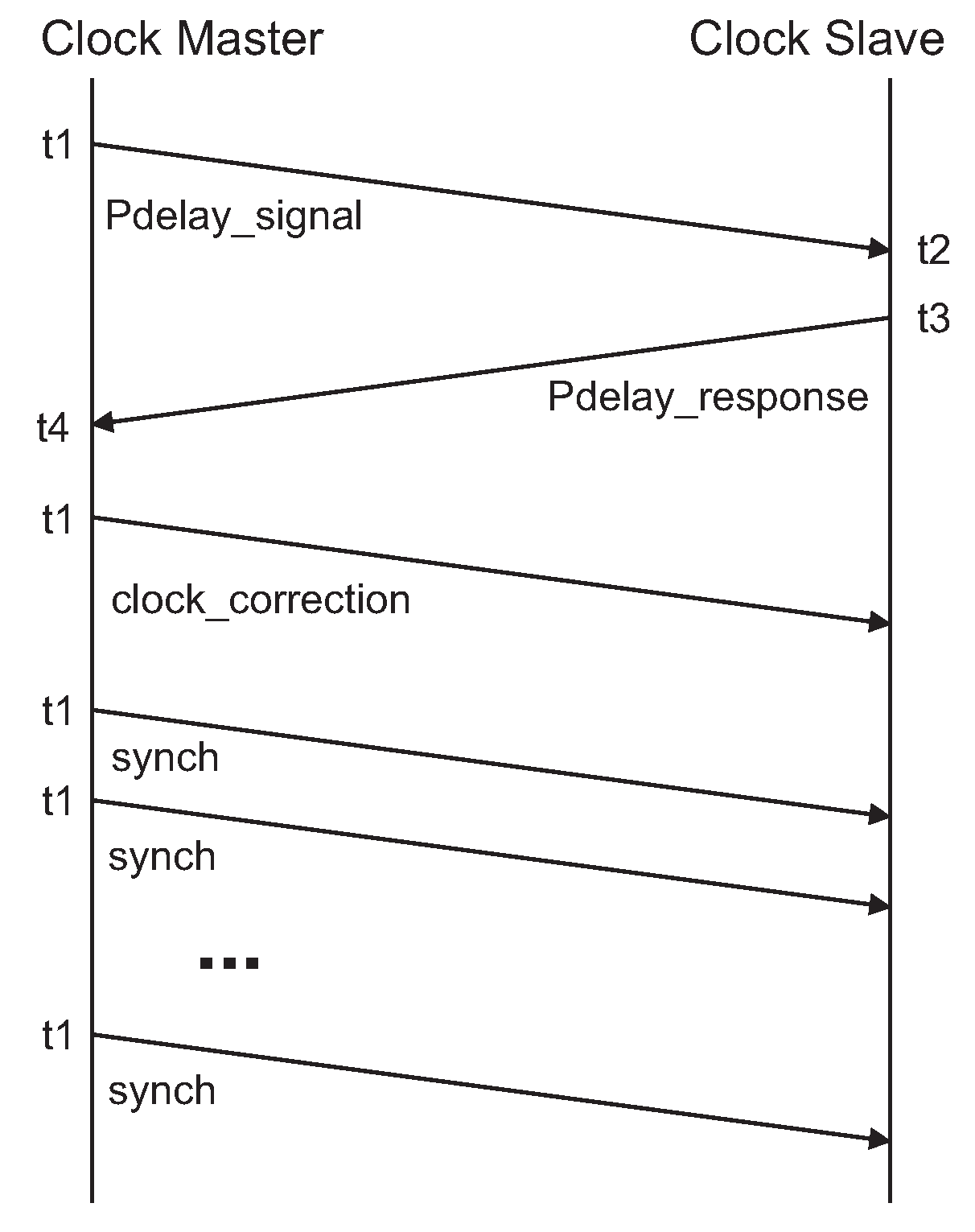
Possibility (1), path propagation delay measurement. Possibility (1) would be to perform a path propagation delay measurement, but with adjustments to improve the performance with wireless interconnections, as shown in Figure 1.
Using IEEE 802.11v, the path propagation delay measurement interval and the synchronization interval are bound together. Separating them like we did, allows one to make more use of a wireless channels broadcast character.
First, the Clock Master broadcasts a Pdelay_signal (generating t 1 ), to which every station has to reply individually. This Pdelay_response contains t 2 and t 3 . With the reception of Pdelay_response, the Clock Master generates t 4 and calculates n r i : = the ratio of the clock of the neighbor time-aware system to the local clock. By that, it knows all necessary information to calculate the path propagation delay as with PTP’s equation:
D i = 1 2 t 4 t 1 n r i · t 3 t 2
Since the path propagation delay is station specific, the signaling of these is still an issue. So generally, there is one clock_correction message per client required. In cases where confidentiality of this information is of no concern, one big message carrying all clock_corrections can be broadcast, which could again save channel occupation. Whichever approach is adopted, after the reception of the clock_correction message, a Clock Slave is able to synchronize more precisely via adding the received clock correction value (aka path propagation delay) to the distributed t 1 of the Master.
If the measurement interval and the synchronization interval are now chosen differently, a very efficient and precise clock synchronization can be practiced after the path propagation delay measurement phase. As every station knows its path propagation delay, it is sufficient for the Clock Master to broadcast its clock value. This approach however makes the assumption that the Clock Slaves (which are wireless stations) remain spatially static.
According to how true this prerequisite is for a given application, the measurement interval may be adjusted. For given definitions:
  • I m : = path propagation delay measurement interval. Time between the start of consecutive path propagation delay measurements;
  • I s y n c : = clock synchronization interval. Time between consecutive clock synchronizations, that is the sending of current clock values by the Clock Master;
  • N s y n c : = number of sent Synch messages (not including the clock_correction message). This results from I s y n c and the remaining time from I m after the measurement is finished;
  • N: = number of Clock Slaves.
This yields a required number of message exchanges of ( 1 + 2 N + N s y n c ) as far as one clock_correction is sent per client and ( 2 + N s y n c ) in case one bigger consolidated clock_correction message is sent. For comparison, the equivalent of an IEEE 802.11v synchronization process would be to fill I m completely with its described cycle, starting with one initial req and resp, giving 2 N ( N s y n c + 1 ) messages for such a period of time.
Since a proper path propagation delay measurement is performed just as with IEEE 802.11v, the achieved synchronization accuracy is the same as in the two step time transfer. While this proceeding already performs well, (2) still involves less overhead at the cost of less synchronization accuracy but still better accuracy than with a default one-step approach.
Possibility (2), distance estimation. As an alternative approach, we propose to estimate the passed transmission delay via the Received Signal Strength Indication (RSSI) directly on the receiving station, based upon the assumption that the received signal strength decreases reciprocal exponential with increasing the distance the signal had to travel.
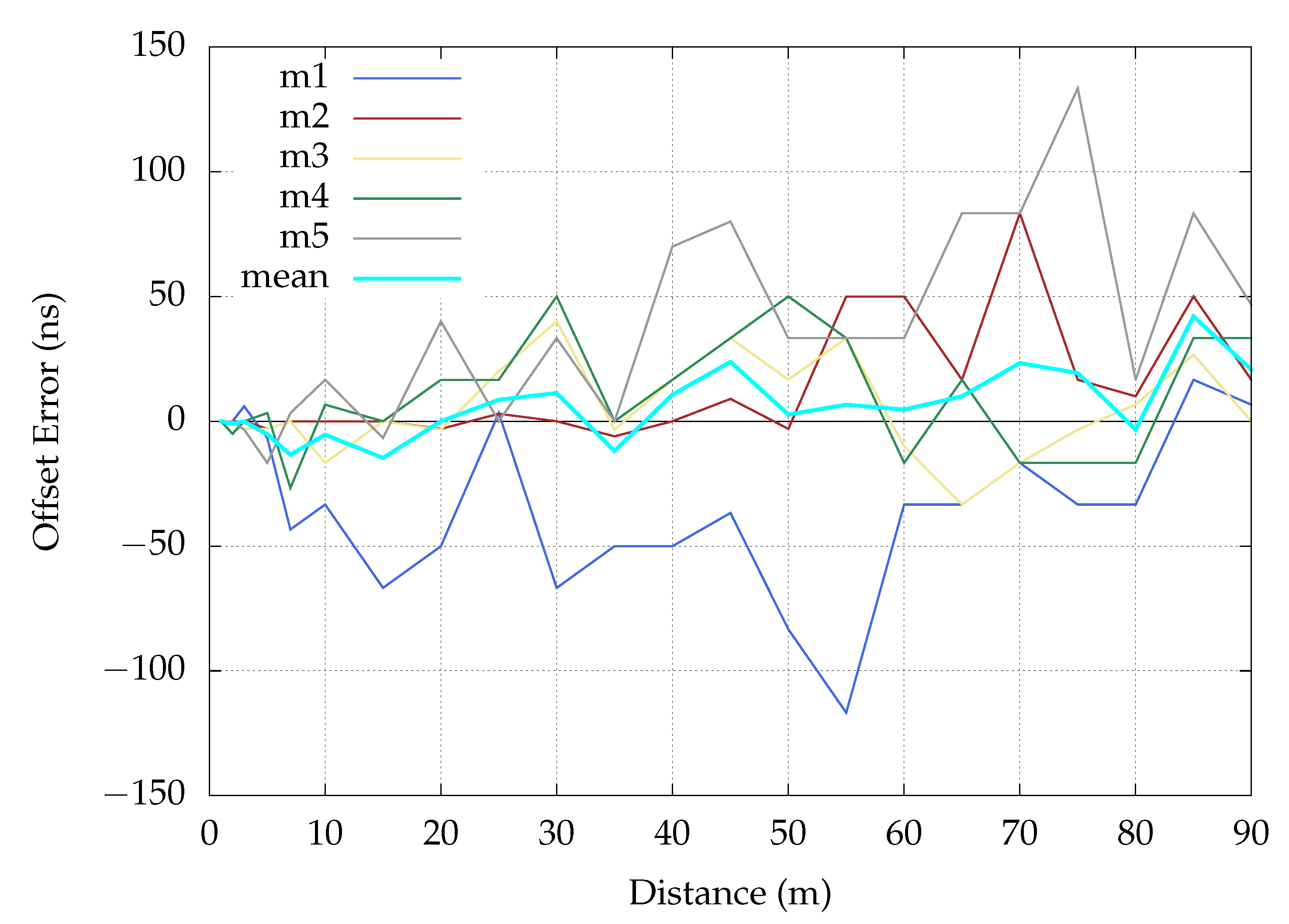
Figure 2 shows measurement results made in a real environment.
For the RSSI measurement in the live environment, the Access Point (AP) was configured with channel 1, channel frequency 2.412 GHz, channel width 20 MHz, and transmit power 20 dBm. The environment was an open area, where the measurements were taken in line of sight. We started the measurement at the distance of 1 m from the access point, initially repeated every 2 m and from 50 m on measured every 5 m, up to 90 m at maximum. Although it is an inaccurate estimation because there are a lot of influencing factors for the RSSI-like multi-path propagation, antenna characteristics, or physical obstacles, which can affect the signals, it is nevertheless very useful since an estimation of the distance already helps to increase the accuracy. Furthermore this way of calculating the distance is very fast and therefore useful. By having an assumption of the distance we can approximate the delay for each client that the timestamp of the first synchronization package had. This is shown in Figure 3, where the clock offset was deduced by the signal strength. The procedure at this point was as follows: Over several signal strength measurements an average was calculated, which can be seen in Figure 2. With this graph the distance can be derived from a signal strength measurement. In a further step, the distance can be converted into a correction of the clock using the speed of light. As in Figure 3 visible, the synchronization error is moving in a corridor between 0 and 140 ns without a correlation to the distance. Furthermore, the synchronization effort in this approach was reduced to a single broadcast message which is optimal for future use cases since the effort does not increase with the increasing number of clients.

3.3. Scheduling

Scheduling is an essential part of TSN. More precisely, time slotted scheduled channel access on the level of service traffic flow, which will be focused on here. This means that each service is assigned a dedicated time slot for exclusively utilizing the communication link. True communication guarantees can only be granted in cases where it is beforehand possible to determine what will happen. A way for that is to time slotted dictate which package will occupy the communication channel at which point in time. In TSN, a schedule defines for each sending node at which point in time messages of which service are allowed to be sent. This schedule is calculated prior to operation and cyclically executed. With having re-occurring defined time slots, during which a specific service is arranged to be transmitted, this scheduled traffic is not disrupted by best-effort traffic or messages of other services not scheduled for this time slot.
In wireless communication, a proper schedule is even more important and in fact, some way of channel access arbitration is already performed anyways albeit for a slightly different purpose. While in most Ethernet interconnections an exclusive transmission medium access can be assumed, radio technology inevitably is a shared medium. In mobile communications like LTE or 5G, the transmission medium resource management performs a combination of frequency and time spectrum coordination, in which a segment of a certain bandwidth is allocated for a certain time span as a resource block to a specific client. In WLAN, all participating devices of a network agree on a frequency band to use and on this wireless channel a Time-Division Multiple Access (TDMA)-oriented sharing of the channel is performed. With TDMA, the transmission capacity of a link is divided in the time domain, which means that accessing devices use it exclusively one after another. It should be noted that the use of TDMA is a deviation from the 802.11 standards. While the whole approach of channel scheduling requires unique handling depending on the wireless technology in use, for all equal is the requirement to control the channel occupation in time, which may then be joined with the time slot allocation on the service level that is performed by TSN.

4. Wireless TSN Functionality Toolbox

The features, covered in 
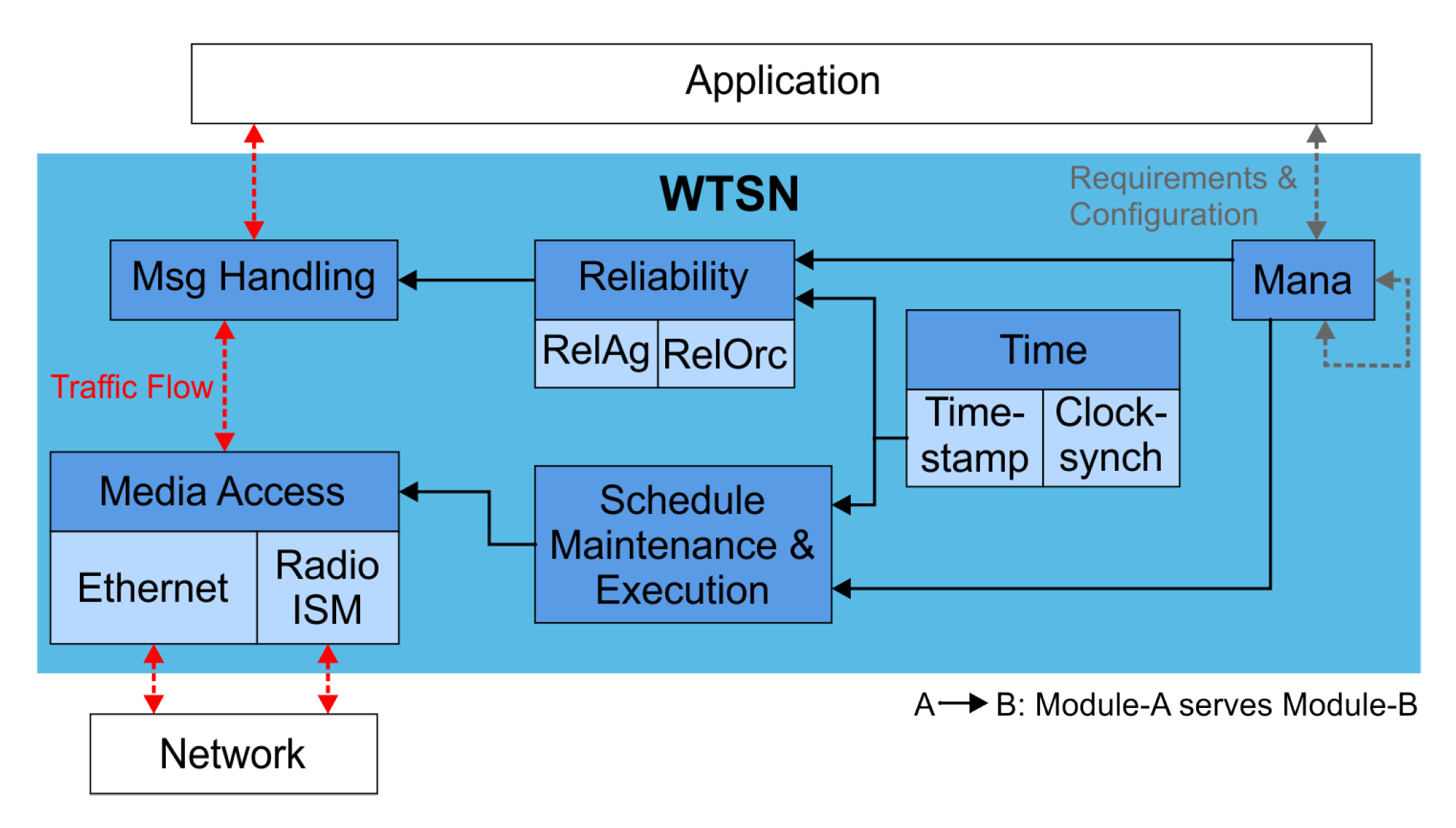
Section 3.1, can be implemented in independent modules, many in software or at least strongly software assisted, giving the opportunity to reuse single functionalities and place them in the Open Systems Interconnection (OSI)-Model where appropriate. The resulting interactions are depicted in
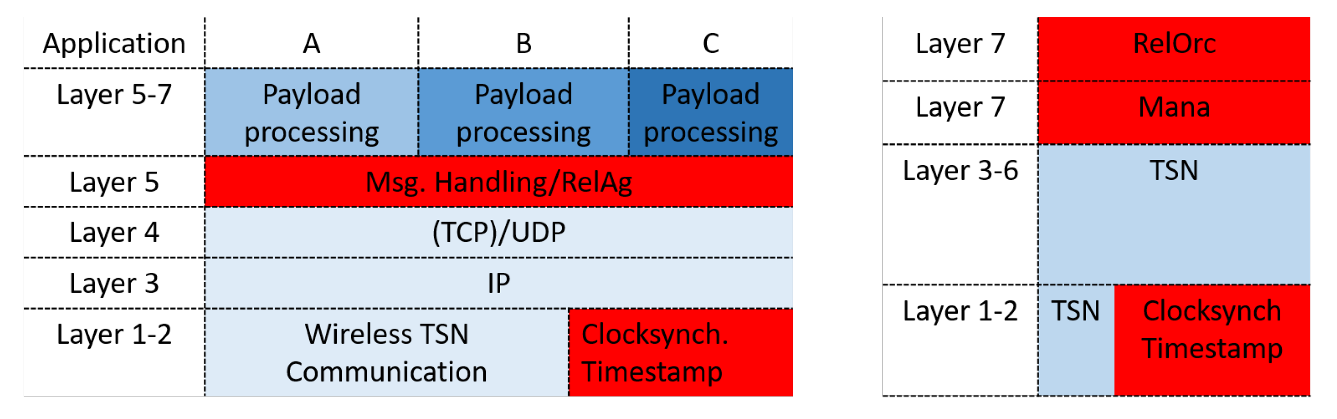
 Figure 4. Figure 5 indicates that a TSN implementation—while essentially introducing management procedures above classical network packet handling—can partly span across and influence multiple lower OSI layers.
There are two points where a real-time application interacts with the (Wireless) TSN toolbox: The Mana (Management) Module and the Msg Handling Module. All other performed tasks happen invisibly, inside the TSN System itself. The Mana interaction occurs prior to an operating state. The application informs its communication demands and subsequently obtains a Talker/Listener configuration. Basically, this step can of course happen repeatedly to refresh a configuration but nonetheless every time preceding a permanent operation, working subsequently according to its resulting configuration. This certainly requires special attention from network applications, which is unique to TSN (as opposed to e.g., best-effort standard Ethernet). During permanent operation though, the only interaction occurs with the Msg Handling module, which is nothing other than the ordinary sending or receiving of messages.
Media Access is the interfacing point between the TSN toolbox and an underlying transmission technology (see Figure 5). In highly compatible cases, as for example IEEE802.1 Ethernet, the additional functionality set of TSN and the actual physical transmission of a packet can be kept separate in the sense that the TSN toolbox simply hands a packet down, which then is sent and vice-versa gets a received packet forwarded up by layer 2. Depending on factors like how stringent regulations for a transmission medium are or fundamental conceptual issues, a strict separation at the transition point above layer 2 cannot always apply.
Regardless of which transmission technology is used below, many parts of the TSN toolbox stay completely unaltered. Some parts are more relevant for specific transmission technologies—as is the Reliability-Agent (RelAg) of particular importance, while using wireless transmission—but are nonetheless equally available in all cases. When finally passing a packet out to the transmission medium, it is possible with a given transmission technology that adaptions to its MAC or PHY layer are required. Due to that, submodules of the Media Access module may be more invasive than only handing a package down to layer 2. They might require a more thorough interface parameterization or even replace certain functionalities. In particular for Wireless LAN (or more general the ISM radio bands), the shared medium radio character deserves serious consideration in terms of the competitive channel access, PHY-layer ACK procedure, automated re-transmissions, and usage regulations.
The Msg Handling module is from an abstract view, mainly responsible for controlling the processing flow inside the TSN toolbox, for payload, which is to be sent for real-time applications. This is the interfacing point at the other side of the toolbox, directed towards network applications. During live operation, messages sent by applications are passed onto the TSN toolbox, where they arrive at the Msg Handling module, which then performs actions using the capabilities supplied by the other functionality modules, according to the requirements for this message. The Msg Handling module furthermore supplies optional interfaces, which allow an application or module in the toolbox to acquire deeper insights in specific internal operations if desired. For instance, a module could ascertain transmission time measurements as it is done in the following by the Reliability module.
The Reliability module is responsible for increasing communication reliability beyond the physical conditions by adding algorithmic analysis and message handling on top of the fundamental network operations. This module is explained in detail in Section 5.
RelAg is running on devices, which communicate using TSN, which will supposedly be a multitude.
Reliability-Orchestrator (RelOrc) is executed on a Central Network Controller, one running instance at a time. The distributed RelAgs are controlled by the one RelOrc.
Mana is what turns a collective of TSN devices operable. It covers the coordination between TSN endpoints, switches, and Centralized User Configuration (CUC)/Centralized Network Controller (CNC): The exchange and collection of demands and capabilities, the calculation and reception of a configuration and therewith tasks performed prior to the sending of messages during live operation. The looping interaction arrow in Figure 4 at the Mana module reflects that an interaction is happening between different Mana modules on distinct TSN entities.

5. Reliability Assurance

At first, we delineate the currently possible level of reliable wireless communication. This can then be considered a baseline for further improvements in future. Following that, we provide an architectural concept, which can be included in the proposed wireless TSN toolbox and that can be utilized as a universal framework for establishing new reliability raising measures in future. This reliability concept, explained from Section 5.2 onwards, provides a software-based algorithmic management basis, capable of increasing the reliability of a communication system and to flexibly integrate new proceedings on an algorithmic level. Algorithmic solutions are characterized with being independent of concrete transmission technologies, possibly functioning across several links, hops, maybe whole network segments. Such approaches are often times controlled by a dedicated instance—a software, controller or coordinated, collaborating collective of distributed instances.

5.1. State-of-the-Art Baseline

Considering the newest Wi-Fi standard IEEE 802.11be, likely designated as Wi-Fi 7, recent performance analysis exist. In [10], a Packet Error Rate (PER)is provided as a function of SNR, which showed a PER of 0.01% to be achieved with an SNR between 8 & 23 depending on the signals modulation and utilized physical measures.
A standardized procedure for increasing reliability is provided by the IEEE standard 802.1CB via Frame Replication and path redundancy. This is also well applicable with wireless interconnections. Frame replication increases the reliability by a stochastic process depending on the error rates of involved parallel transmission paths. Combining it with frequency diversity allows for more specific optimization in a wireless environment.
While for example IEEE 802.11be is a communication technology that hence utilizes physical and MAC layer solutions to improve the reliability of a single p2p link, IEEE 802.1CB is an example for an algorithmic solution.

5.2. Improving Approach

Following, we propose another modular design concept, which for one can be integrated into the toolbox introduced in Section 4 and secondly is as modular by itself as it allows one to flexibly and transparently invoke new reliability algorithms. As the baseline for reliable communication as with the current state-of-the-art, IEEE 802.1CB can be assumed, which is then to be improved by upcoming techniques. IEEE 802.1CB could be used as part of our reliability concept. However the application of frame replication is better performed by configuring it as part of the basic system setup and using it only on network paths, where appropriate. Subsequently, our reliability concept can be deployed on top to either raise the reliability even more or to make it more adaptive.
A dependable or reliable TSN network, regardless of wireline or wireless communication, is characterized by a high probability for a successful transmission within a certain time frame. Since this is an application viewpoint on the problem, the border for the network and its needed reliability would be between Layer 4 (Transport) and 5 (Session) in the OSI model on the Client side. There will never be a hundred percent probability for a successful transmission.
Hence, the task arises to handle the delta between the realistic reliability percentage and the hundred percent that is desired to achieve. A wireless channel is even more critical in this aspect since the physical restrictions to interfere this channel are minimal.
For a reliable communication, the detection of failed transmissions is just as important as the transmission itself. In order to provide a certain monitoring and control loop for wireless transmissions, there are certain aspects to have in mind. It is necessary to make sure that the packet was not only received but was received within a certain time.
In case a packet does not arrive in time, the Industrial application would stop operating. The problem here is that the information of packet loss is tied inside the application (in layer 7 of the OSI model) and the network would not get any feedback. This information can be helpful for the network to either prevent a message from missing the time frames so as to repair the network and initiate a fallback solution, or at least let the engineer know that a packet was lost and where the error is. The border between the applications and network, as it was defined previously, is the handover point from network to application.
The data and the meta information at this point is of special interest to determine the achieved reliability. For instance, for time critical information it is important to access the network at the right time as well as leaving the network at the destined client at the right time. This example illustrates that there are several timestamps necessary to determine the success of a single transmission, which have to be captured on different clients. These distributed information require an equal distributed processing system and precise synchronization, as already introduced, in order to have timestamps that are reliable.
A solution to this problem can be to integrate a reliability module below the applications to introduce an additional round of pre-processing. Since such an intercepting layer is already present with the presented WTSN toolbox, the reliability concerning processing is a functionality delivering module, connected to the Msg Handler, processing timestamps and other meta information.
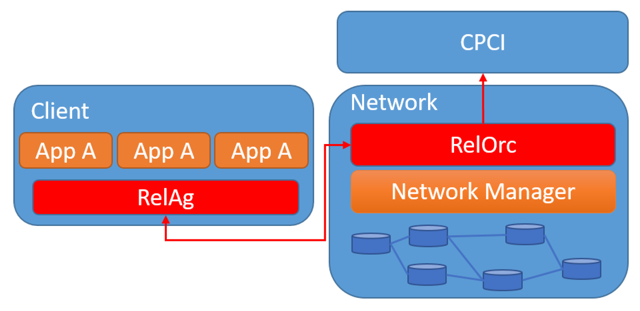
Figure 6 shows the architecture of the Reliability modules separated. On the client side, there is the RelAg that is responsible for collecting and processing the meta information from the Msg Handling module.
The counterpart to these distributed agents is the RelOrc that is shown in the architecture on the network side. Main responsibilities of the RelOrc are collecting meta information from the RelAg, in order to put the information into context to perceive the end-to-end picture.
On the other side the RelOrc is connected to the Central Process Control Instance (CPCI). The CPCI is an interface to personnel that observes the production. It is assumed that in any emergency that is detected and that can not be resolved by software itself, this is the interface for both, the RelOrc and network manager, for setting warnings, error feedback, or further instructions. This might be instructions bringing up another Access Point or another Switch, or warnings like a certain application has stopped working. Furthermore, the RelOrc is connected to the Network manager, which is in the case of TSN, the Centralized Network Configuration (CNC) or in WLAN the Access Point, to enable a control loop in order to resolve detected errors.
These are management instructions or suggestions, exchanged between the RelOrc and network manager. The interactions in the architecture are described in more detail in the following subsections.
The proposed TSN toolbox already serves as a decoupling interface between application and network. This allows in principle to transparently insert additional functionality and to higher abstract the communication. The reliability module will bring a lot of benefits for time critical applications. In the first step, it can be used as a benchmarking tool, in order to measure data throughput on the network as well as timing of various packets. In this scenario it is important for the RelAg to be synchronized with the network, otherwise only relative time measurements can be handled, like the continuity of a cycle time. Another benefit is that this benchmarking is not part of an initial network test phase but can be done live since the message handler will forward the timestamps to the RelAg in a continuous manner while the network and applications are online.
A second feature arises with the RelOrc. As already mentioned, this is the counterpart for the RelAg which means this is the aggregation point for the data collected by the distributed RelAgs in the network. Another responsibility for the RelOrc is the sorting and clustering of the information coming in and deriving management reactions for the network, which are highlighted in the next subsections.

5.3. Acquisition of QoS Parameters

A main reason for inserting a TSN Toolbox as well as for a Reliability Layer is to abstract the communication issues from the application, sender, and receiver, as far as possible. The application itself will be released from all communication tasks and therefore will be able to put all responsibilities in the hands of the network. The term Communication as a Service (CaaS) fits this context very well.
The main contribution to the provisioning of this service is done by the Centralized User Configuration (CUC). In TSN, the CUC is defined as the centralized entity that discovers end stations, retrieves end station capabilities and user requirements, and configures TSN features in end stations. The Mana will collect the information of QoS parameters and relevant client configuration from the CUC and provide it to the RelAg, in order to continuously inspect the measurements of the RelAg for matching the requirements.

5.4. Reliability Functionalities Conducted by RelAg

The RelAg acts as the gatekeeper for time sensitive communication. If any part involved in the QoS requirements is violated, the RelAg will detect it and will report the violation to the RelOrc.
The reliability functionalities that serve these detection missions are highlighted in more detail in this section. To begin with simple and obvious solutions, the RelAg will detect a packet loss of real-time critical packets. This can be done because the RelAg knows when a real-time packet is supposed to arrive. In case of a missing packet, the receiving RelAg has the possibility to react with a re-transmission request to the sender. This request will only be sent if re-transmission will still meet the deadline. Important here are two factors. Firstly, the time to deadline should be at least double that of the transmission time and secondly, the schedule should contain a sending slot before the deadline. If these two aspects are valid, the re-transmission will be triggered. If the re-transmission can not be triggered or was unsuccessful, the packet will be considered as not received meaning a violation of the QoS requirements. Important to mention at this point is that the RelAg will not only measure violations committed by the network but also by the application. This might be a payload that exceeds the agreed size coming from the application or a timing constraint that is not fulfilled by the application. Important here is that other re-transmission functionalities in other OSI layers, like TCP or WLAN re-transmissions are disabled, to avoid multiple re-transmissions. Information of these mentioned detection functionalities will then be sent to the RelOrc immediately. In some cases in future scenarios, it might also be possible to give feedback to the application. Furthermore, the RelAg will send all timestamps together with packet size and source and destination information as a bundle to the RelOrc. The cycle of these meta information packets depend on the requirements of the detection performance. Obviously the faster the cycle, the faster the detection of possible changes in the network behavior, but more additional network load is generated.

5.5. Processing Overhead Induced by RelAg

In toady’s program landscape there is only a very limited number of real-time requiring applications. In most cases found in the industry, there is time restrictive interaction between sensors, controls, and actuators. Applications running here are mostly delivered with dedicated hardware like micro-controllers or FPGAs. On these systems, processing power is a limited source that must be considered. Since the RelAg is not only an additive processing effort but also substitutes efforts that an application would have to handle the final processing overhead is caused by the functionalities that go beyond the reception and extraction of the payload. Although this might cause problems in some tightly fitted systems it is not assumed to cause any significant processing overhead. Furthermore, with the upcoming of sophisticated real-time operating systems it is assumed that stronger hardware will be used and the lack of processing power should be a minor problem in the future.

5.6. Data Processing Conducted by RelOrc

There are two different data sources that the RelOrc has to manage. First are the direct warnings of malfunction sent by the RelAgs. This information is directly forwarded to the CPCI in order to inform an system engineer of a critical packet loss. The second source are the previously mentioned meta information bundles. The RelOrc will receive the meta data from the RelAgs and then start with the processing of the data immediately.
The processing is performed in two stages. In the first stage, the data pairs will be merged. A pair of data is the dataset from the sending RelAg of a packet merged with the dataset of the receiving RelAg of the same packet. By doing so, it is possible to calculate the transmission time, which is the time difference between sending and receiving. This tuple of information can than be compared to the configured schedule of the network and the required QoS of the application. Depending on the outcome of this comparison, there are three possibilities for a tag that will be added to the data pair. Data that passed the QoS requirements and the expected transmission time of the network is tagged as successful. Data that passed the QoS requirements but were not transmitted according to the configurations expectations are tagged as critical and in the last case, data pairs that did not meet the QoS requirements are tagged as failed. A failed transmission will directly cause a warning for the CPCI, whereas a critical tag will not cause any direct consequence. After being tagged, the data pairs will be forwarded to the second processing stage.
In the second processing stage, the data will be processed by an AI that is responsible for classifying the data. This topic will not be highlighted further since this is an ongoing work and not finalized yet. The clustering as a result will give an assumption of the underlying malfunctions in case of critical or failed communication. The AI should distinguish at least the following cases. In case of a single critical or failed transmission, the error is assumed to be in an exclusively used node of this transmission that might be the sending or receiving clients or an exclusively used communication path. If the same transmission fails frequently, it might be again an exclusively used resource or a configuration error like a schedule configuration or calculation. A periodically repeated or a burst of critical or failed transmissions gives rise to the suspicion that another machine interferes with the communication, e.g., a microwave that emits frequencies on the same band as WLAN. Otherwise, it might be another subnetwork that is on the same channel and also interferes with the communication in a repetitive way. In case of uncorrelated errors that do not follow any pattern, it is assumed that another communication network on the same frequency causes interference. This assumption is made because an interference that eliminates single transmissions has to have a highly time selective sending pattern itself, which is, to the knowledge of the authors, unique for communication systems

5.7. Network Management Triggered by RelOrc

The RelOrc is a central aggregation point for the data that is sent by all RelAgs in the network.
Once the configuration of the network is set and the communication is running, the RelOrc will receive the monitoring packets from various RelAgs. This data will then be processed and clustered in order to find correlations on a higher level. These results can be forwarded to a higher control instance where personnel can observe these data or/and the RelOrc will derive management solutions in order to optimize the network performance. These management instructions might be for example to trigger a channel selection for the wireless channel in case there is interference assumed for a client. This might be because the transmission took too long or a packet got lost. Furthermore, it might also be sufficient to reduce the modulation coding scheme to improve the SNR or vice versa increase the modulation coding scheme if the transmission takes too long. There are several more possibilities that can be triggered on certain events, as increasing the transmission power if a client loses signal or vice versa if there is a risk of interfering with another wireless transmission. Another possibility that the RelOrc might have is to put the application on the client into a failsafe mode if the communication is expected to be interrupted. This might as well be triggered by the RelAg if the connection is already lost.

5.8. Network Overhead Induced by RelAg

The RelAg will indisputably add traffic overhead to the network, since there are the monitoring information that have to be sent to the RelOrc continuously. So the question arises if this added load is significant or negligible. To answer this question, the increased data have to be determined and put into context of the achievable data rate. For the first aspect of induced extra information into the packets the amount of data is minimal, since it will be 64 Bit for the identifier. This sums up to 8 Byte per application data packet. The second type of traffic that is induced is harder to determine since it strongly depends on the amount of application data packets per client and then the amount of clients. These two added data sources are not expected to add a significant amount of additional data.

6. Conclusions and Future Work

The essence of the paper showed a new concept to deal with communication in an industrial environment given the ability to separate the application completely from the communication and therefore going the next step to increase reliability. The approach described here was deliberately kept very restrictive and minimalist in order to draw attention to the core functionalities. However, the idea of an end-to-end management and monitoring application could be taken much further. For example, various security concepts could be implemented uniformly for all applications or application specific redundancy requirements could be fulfilled. A network engineer gains full access to all communication aspects in their network and is therefore able to use its full potential without having to modify every application.
In future, the concept will be enhanced in order to detach software and hardware for industrial applications as it is known by consumer products. By doing so, the deployment of software will be easier and the cloudification of industrial applications will be enabled.

Author Contributions

Conceptualization, C.F. and D.K.; Investigation, D.K. and M.K.; Software, C.F. and D.K.; Writing—original draft, C.F., D.K. and M.K.; Writing—review & editing, D.K. and M.K.; Supervision, H.D.S. All authors have read and agreed to the published version of the manuscript.

Funding

This research received no external funding.

Conflicts of Interest

The authors declare no conflict of interest.

References

  1. Khorov, E.; Levitsky, I.; Akyildiz, I.F. Current Status and Directions of IEEE 802.11be, the Future Wi-Fi 7. IEEE Access 2020, 8, 88664–88688. [Google Scholar] [CrossRef]
  2. Adame, T.; Carrascosa, M.; Bellalta, B. Time-Sensitive Networking in IEEE 802.11 be: On the Way to Low-latency WiFi 7. arXiv 2019, arXiv:1912.06086. [Google Scholar]
  3. IEEE. IEEE Standard for Local and Metropolitan Area Networks–Timing and Synchronization for Time-Sensitive Applications. In IEEE Std 802.1AS-2020 (Revision of IEEE Std 802.1AS-2011); IEEE: Piscataway, NJ, USA, 2020; pp. 1–421. [Google Scholar] [CrossRef]
  4. Shao, W.; Luo, H.; Zhao, F.; Tian, H.; Yan, S.; Crivello, A. Accurate Indoor Positioning Using Temporal-Spatial Constraints Based on Wi-Fi Fine Time Measurements. IEEE Internet Things J. 2020, 1. [Google Scholar] [CrossRef]
  5. Krummacker, D.; Fischer, C.; Alam, K.; Karrenbauer, M.; Melnyk, S.; Dieter Schotten, H.; Chen, P.; Tang, S. Intra-Network Clock Synchronization for Wireless Networks: From State of the Art Systems to an Improved Solution. In Proceedings of the 2020 2nd International Conference on Computer Communication and the Internet (ICCCI), Nagoya, Japan, 26–29 June 2020; pp. 36–44. [Google Scholar] [CrossRef]
  6. Gundall, M.; Huber, C.; Rost, P.; Halfmann, R.; Schotten, H.D. Integration of 5G with TSN as Prerequisite for a Highly Flexible Future Industrial Automation: Time Synchronization based on IEEE 802.1AS. In Proceedings of the IECON 2020 The 46th Annual Conference of the IEEE Industrial Electronics Society, Singapore, 18–21 October 2020; pp. 3823–3830. [Google Scholar] [CrossRef]
  7. Karrenbauer, M.; Weinand, A.; Melnyk, S.; Schotten, H.D. On industrial mac protocols: State of the art systems and recent approaches. IFAC-PapersOnLine 2018, 51, 40–45. [Google Scholar] [CrossRef]
  8. IEEE. IEEE Standard for Local and metropolitan area networks–Frame Replication and Elimination for Reliability. In IEEE Std 802.1CB-2017; IEEE: Piscataway, NJ, USA, 2017; pp. 1–102. [Google Scholar] [CrossRef]
  9. Kirrmann, H.; Weber, K.; Kleineberg, O.; Weibel, H. HSR: Zero recovery time and low-cost redundancy for Industrial Ethernet (High availability seamless redundancy, IEC 62439-3). In Proceedings of the 2009 IEEE Conference on Emerging Technologies Factory Automation, Mallorca, Spain, 22–25 September 2009; pp. 1–4. [Google Scholar] [CrossRef]
  10. Fabris Hoefel, R.P. IEEE 802.11be: Throughput and Reliability Enhancements for Next Generation WI-FI Networks. In Proceedings of the 2020 IEEE 31st Annual International Symposium on Personal, Indoor and Mobile Radio Communications, London, UK, 31 August–3 September 2020; pp. 1–7. [Google Scholar] [CrossRef]
Figure 1. Two way clock synchronization, optimized for wireless communication.
Information 12 00012 g001
Figure 2. Received Power in the context of distance. Plotted are eight measurement series (m1–m8) and the calculated mean.
Information 12 00012 g002
Figure 3. Clock offset after distance correction. Plotted are five measurement series (m1–m5) and a calculated mean.
Information 12 00012 g003
Figure 4. Modular architecture for a reliability assuring WTSN toolbox.
Information 12 00012 g004
Figure 5. Reliability Application in the OSI context (client left side and network right side).
Information 12 00012 g005
Figure 6. Software architecture.
Information 12 00012 g006
Publisher’s Note: MDPI stays neutral with regard to jurisdictional claims in published maps and institutional affiliations.

