Article

Development of Control Experiments for an Online Laboratory System

Institute of Automotive Mechatronics, Faculty of Electrical Engineering and Information Technology, Slovak University of Technology in Bratislava, Ilkovičova 3, 812 19 Bratislava, Slovakia
*
Authors to whom correspondence should be addressed.
Information 2020, 11(3), 131; https://doi.org/10.3390/info11030131
Submission received: 19 January 2020 / Revised: 17 February 2020 / Accepted: 20 February 2020 / Published: 27 February 2020
(This article belongs to the Special Issue Online Experimentation and the IoE)

Abstract

:
Remote experiments have been gaining a lot of popularity over the last years. They are available for many areas including control education. The majority of laboratories available via the Internet were developed from scratch and lack modularity, which enables their easier adaptation. Crucially, the diversity of experiments that can be performed on a single device is quite limited. Along with the prospect of simple integration of new devices and simulation environments, this approach presents a way to more effectively utilize the available resources. The presented online laboratory system offers a possibility of an easy integration of new control experiments to the online environment. It allows users to define selected variables inside their block diagrams, upload them to the system and later initialize them within the system’s graphical user interface. The system was tested on a new developed air levitation plant that can be controlled via Matlab simulation environment.

1. Introduction

Remote experiment is a term describing a real device designed to conduct experiments over the Internet. Upon launch, relevant data is collected and displayed to the user via a web browser or other client application either during or after the experiment runs. This interface may also provide the ability to define input parameters that affect the course of the experiment and device behavior. It eliminates the need for physical interaction. This means that experiments can be run from any location and without time limits. Performing experiments in this way is also much safer in terms of protecting the user as well as the device itself, as incorrect handling is ruled out. Examples of remote experiments and experimentation were already described in many publications (see, e.g., [1,2,3,4,5,6,7]).
In recent years, a tendency to create more complex systems for managing remote experiments has appeared. These systems are commonly referred to as “remote laboratories”or together with “virtual laboratories” as “online laboratories” [8]. Several such web portals already exist around the world. They are mostly managed by educational institutions. There are also systems that cover multiple devices in different physical locations and use the resources of several universities (Table 1). In future it is expected that they will be also required to follow the IEEE standard for online laboratories [9] that was published recently.
In addition to facilitating access to experiments, these systems also provide features such as authentication, authorization, and device reservation. This allows for more efficient allocation of machine time with individual experiments and provides the possibility to monitor their use. The obtained data can contribute to the optimization of the educational process.
Online laboratory system should adapt to changes easily. It is necessary to integrate new devices and implement new simulation environments regularly, so new technologies can be incorporated to the educational process. The ability to innovate and grow is therefore essential.
These changes should not hinder the users in any way. A unified access to all experiments has to be established. Each experiment and software solution requires a different approach when it comes to communication, hence a number of interfaces were created to facilitate the data flow between the interchangeable parts of a laboratory. Every interface handles a different task and is built on a different technology for which it is best suited [10].

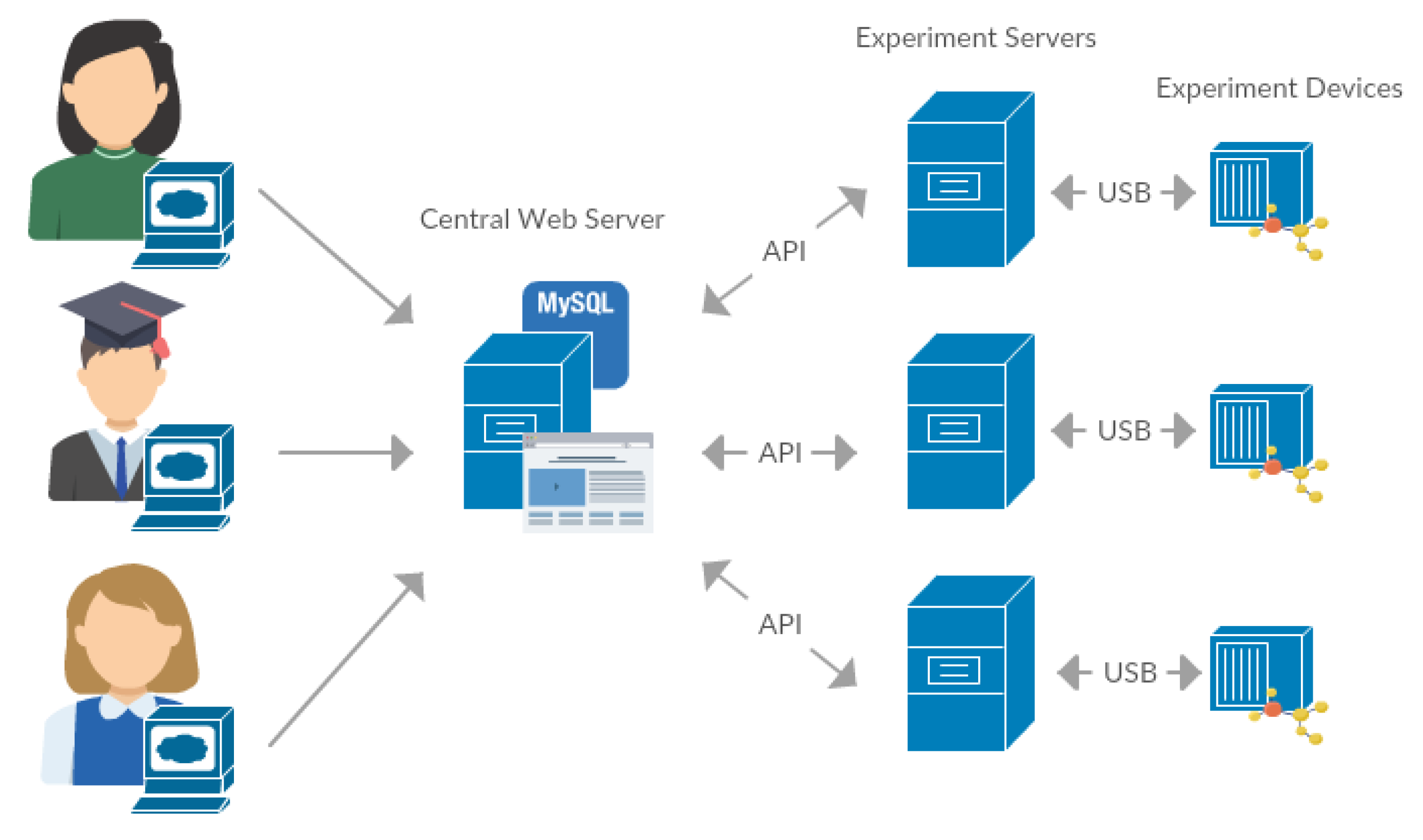
2. Laboratory Architecture and Data Flow

To maximize modularity within the laboratory, all of its parts are arranged in a star topology with a central server acting as a center node. The central server is the interface between the users and experiments. Its role is to facilitate a unified platform for experiment reservation, user management and control algorithm configuration. The experiments consist of a real device and a dedicated server. This experiment server is connected to the central server via Internet and to the device by a serial connection, generally a USB cable. More information about the architecture (Figure 1) and data-flow within the system is provided in [11].

2.1. Commands and Parameters

To simplify the integration of new experiments to the system, each device implements four different commands - stop, start, init and change.
The initialization command serves to prepare the experiment device to a state where it can safely operate and perform the experiment correctly. This is not necessary for all devices, so the implementation of this command is not mandatory.
The termination of the experiment is handled by the stop command. It does not require any arguments and simple stops the experiment process before the intended end time if the user decides to do so.
To change the experiment parameters during its runtime a change command must be issued. It generally requires the same arguments as the start command.
The main focus of this paper is the start command. It launches the experiment process and defines all of its variables. The data transmitted from the central web server to the script implementing this command can be divided into four separate categories.

2.1.1. Identifying Parameters

These parameters contain information about the device and simulation software. If the connected device is capable to run with several simulation environments (Matlab, OpenModelica, Scilab, etc.), these parameters serve to determine which one is used. In addition, the device type specification and also the identification string of the particular instance is also transmitted. For now, this is just another layer of validation, but in the future more than one device might be connected to the experiment server and distinguishing between them will be crucial.

2.1.2. General Parameters

These data do not change with changing simulation environment or even the connected device. General parameters include, for example, the simulation time or the sampling period.

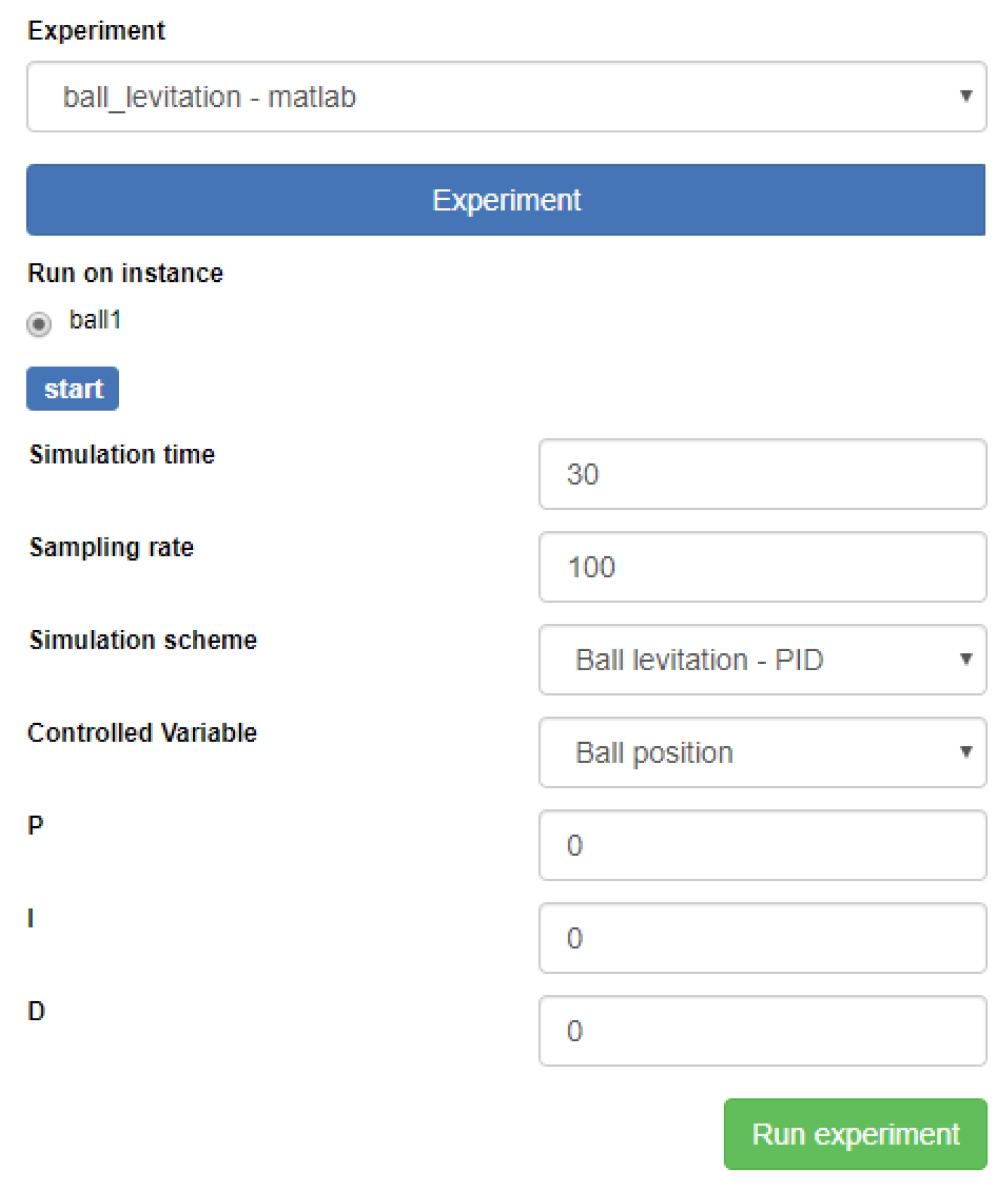
2.1.3. Experiment Specific Parameters

This data might be different for each experiment device.

2.1.4. Schema Specific Parameters

The experiment requires additional data that is specific for each implementation. A control algorithm is specified in a file created using a simulation environment. In case of Matlab it can be an .mdl or .slx file. The algorithm selected by the user to test on a real device is automatically downloaded to the experiment server using the central web server API. The defined controller can contain several more variables, such as the P, I and D values of a PID controller.

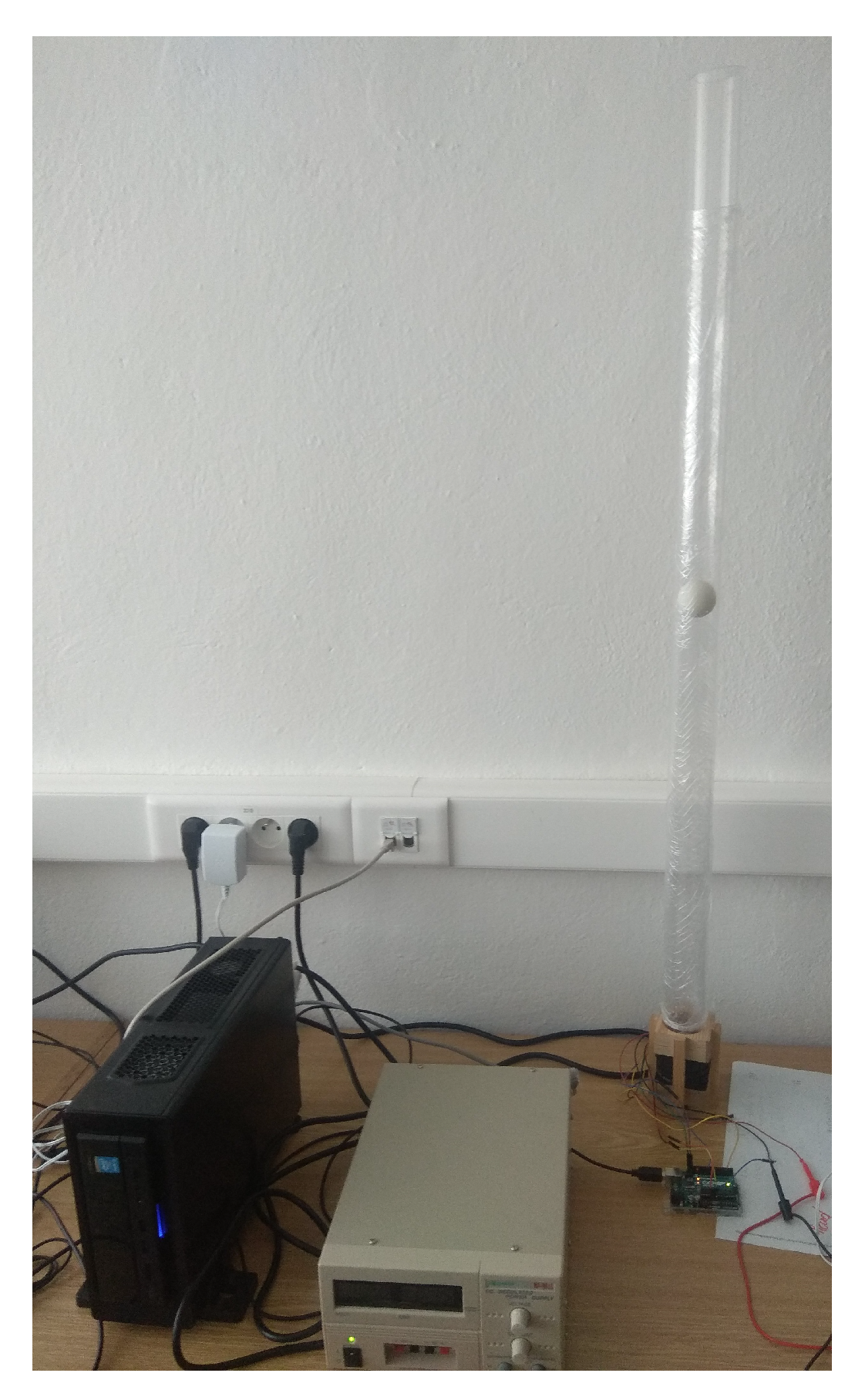
2.2. Connected Device

The ball levitation device (Figure 2) was built to test and verify system’s unified interface for easy integration. It is a simple one input two output system, that consists of a transparent vertical tube with a fan mounted to its base. Various similar plants already exist and have been successfully introduced to different online laboratory systems or work as standalone remote experiments [12,13,14,15,16].
The flow of air generated by the fan lifts a ping-pong ball situated inside of the tube. The air current is controlled by a PWM signal altering the rotation speed of the fan. The height to which the ball rises is measured by a laser-based proximity sensor. More on this device is written in [17].

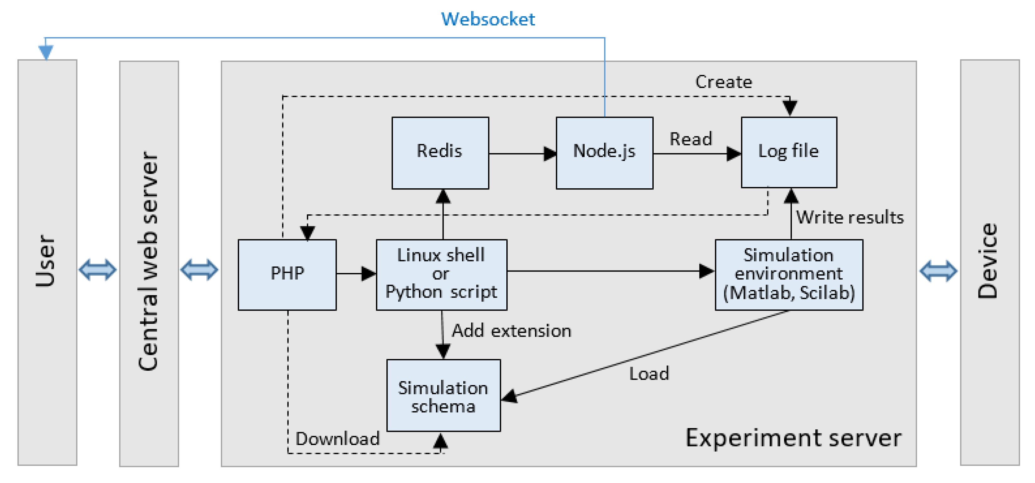
3. Simulation Environment Integration

Simply passing parameters to a device and reading values from its sensors would not be enough to facilitate the process of teaching control algorithms. Handling the device this way might be useful to figure out the device dynamics, but to actually achieve some level of regulation, a feedback loop must be established.
Arguably the best way to achieve this level of control is to use simulation environments. Matlab is widely used and learning how to use it is beneficial for the students.
There are two different approaches when it comes to interfacing an experiment device to Simulink. Previously connected devices (see e.g., [18]) are generally represented by a single block in a diagram. This block is created as an S-function. Developing this subroutine can pose a challenge for people not well-acquainted with Matlab as a programming language. However, once created, it is simple to use and implement in different experiments.
Second approach is to take advantage of already existing built-in functionality for serial communication in the form of “Serial send” and “Serial receive” blocks. These kinds of diagrams are much easier to develop, but not every device can be connected without any issues. Problems might stem from unsupported communication protocols or transmitted data formats. Since the described device was developed with the goal of integrating it to the online laboratory system in mind, it is able to communicate in this manner.
Regardless of the device representation, the online laboratory system lets users create their own block diagrams to test different control algorithms. This means that the emphasis was placed on not just running a single experiment defined by one block diagram, but on the ability to create, alter and test new ones. With multiple possible variables defined within the diagram, users can rapidly change these values without altering the diagram itself or even reuploading it to the server.
The problem arises from the communication between the simulation environment and the PHP server. Since there is no functionality integrated in the PHP language to issue commands to Matlab, a new interface had to be created to handle the communication. This is resolved by a Python script, that is executed by the server.
The process of obtaining the correct simulation algorithm file might seem trivial but actually poses a few challenges. Since actually multiple different simulation environments might be implemented, the files are stored without a designated filename extension on the central web server. A proper one is attached once the file is downloaded to the dedicated experiment server. Matlab is not capable of loading a file without an extension. The same rule also applies to other environments, e.g., Scilab.
Even though these files are generally not taking up a sizable part of a hard drive, it is a good practice to erase them once the experiment has concluded. Since their name is altered by adding the extension, they are located and deleted with the use of a regular expression or regex.

3.1. Linux Shell Script Interface

All of the necessary input arguments are passed to a linux shell script. In the past these were generally written in bash, but recently due to several advantages Python is being preferred. Matlab provides an API for Python since the R2014b version. Thanks to this, it is possible to start the simulation environment, load the block diagram downloaded from the central web server and initialize declared variables.
For each supported simulation environment a separate set of dedicated scripts must be created. These are the scripts written for the different commands. The optional init command is not necessary in this implementation. To prematurely terminate the experimentation process, the stop command shuts down the fan motor by setting the PWM signal’s duty cycle to 0%. Running the experiment is the most complex task so the start command is usually the one that is the most difficult to implement.
Starting the Matlab software each and every time a new experiment request is issued would be extremely taxing on the server performance. Luckily, it is possible to run Matlab as a shared engine in the background, which means that different processes can access its resources.
When the start command script is executed, it searches for a running instance of the Matlab software and connects to it. It sets the values for the variables and initializes the experiment through a set_param() command. To execute this command Matlab needs access to the graphical user interface and cannot be executed solely by a command line instance. A supervisor script ensures that this program does not close, or more exactly, if closed or terminated is swiftly relaunched.

3.2. Matlab

The script implementing the start command sets the value of the experiment output file to the simulation environment. Its filename is a combination of an ID number of the logged-in user and a string of characters representing the current time. This rules out the possibility of inadvertent duplicate files, but also it serves to categorise the files mainly for debugging and troubleshooting reasons.
While the experiment is taking place, the sensor data is periodically written to the specified log file. This file is read in a predefined time interval by a Node.js server and its contents are sent through a websocket directly to the connected user’s internet browser. More on this functionality can be found in [19]. The flow of data within the system is displayed in Figure 3.

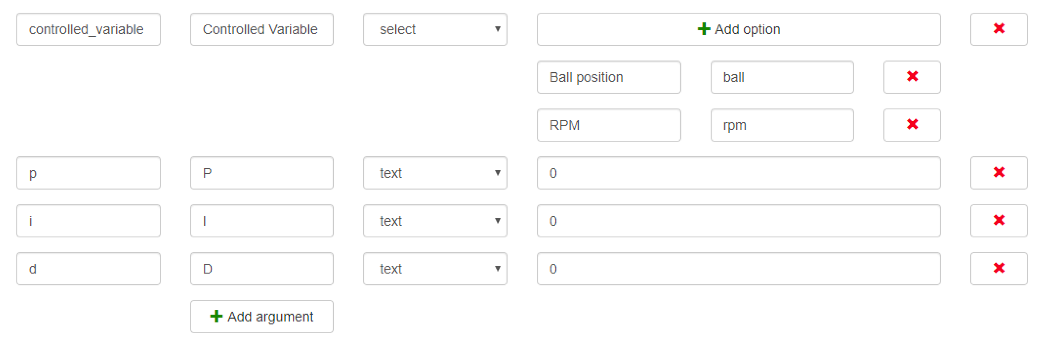
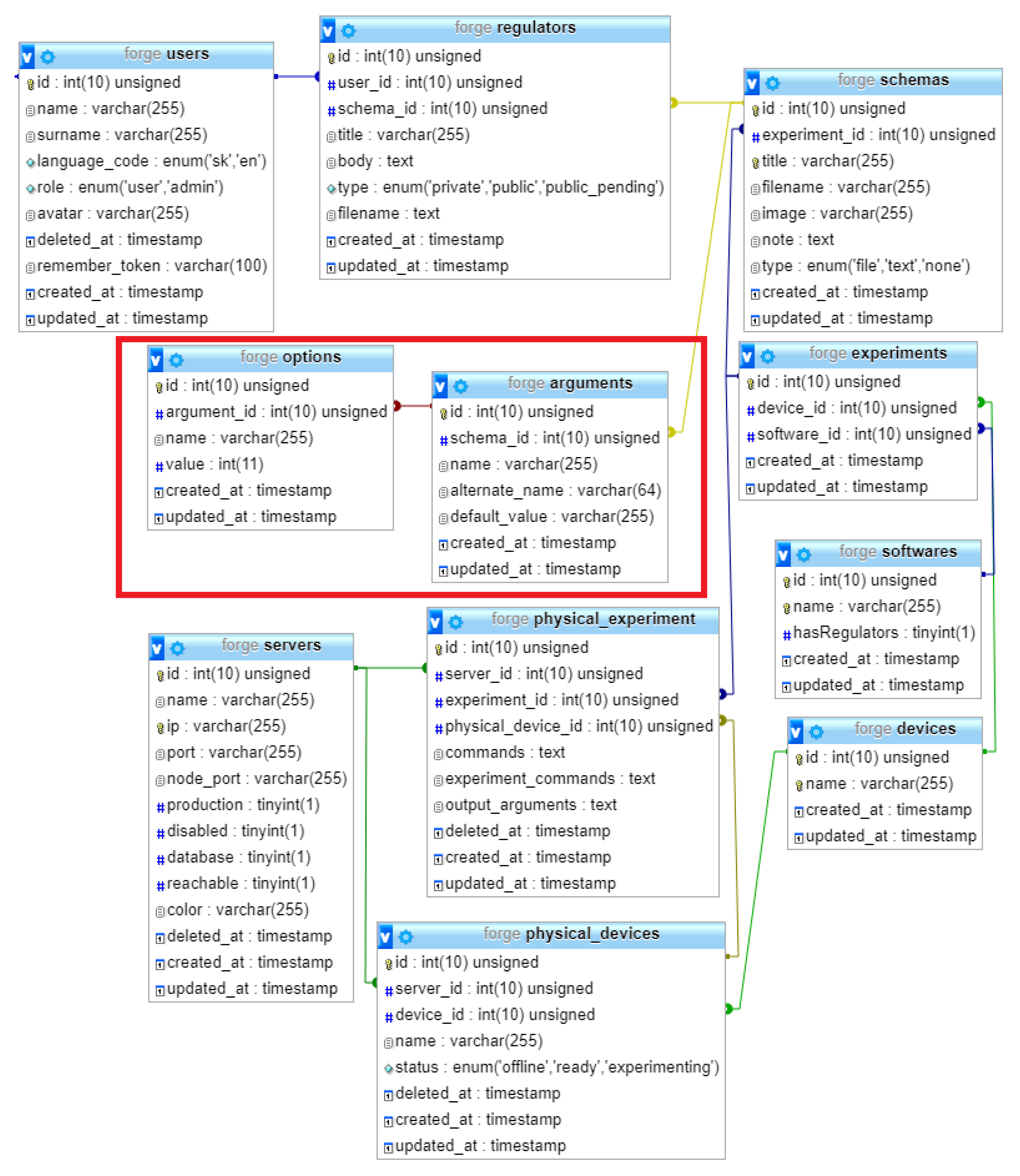
4. Passing Arguments

The experiment input parameters declared by the developer and later initialized by the user might not always be a simple numerical value. It is possible to declare variables of any data type and even to determine a set of their possible values. This might serve to reflect a hardware limitation, to create a problem for the student or simply to protect the device from unwanted and potentially dangerous states of operation.
An user interface to both declare these variables and also initialize them was created, so the process is simplified. The layout and behaviour of the interface is also the same for all of the connected devices and also all implemented simulation environments. Its contents are generated based on the specific experiment.
The user must have the ability to pass any defined values within the input parameters sent to each simulation environment while the start command is being issued. This argument can have various forms or data types, so there must be a comprehensive and intuitive user interface that provides these options. The user interface provided by the system for users to define the arguments can be seen in Figure 4.
The declared variables along with their labels and placeholder values are stored in the central web server database. Once an experiment control panel is opened, a new HTML form is generated to reflect each specific implementation.
All of this combined assures that the user can select from a variety of real devices and simulation software, but also it is possible to have a variety of different control algorithms defined for each device type (Figure 5).
Figure 6 shows an entity-relation diagram illustrating the stored tables and their attributes. The diagram also visualizes some important connections to other tables to better demonstrate the inner workings of this online laboratory system. The section visibly marked by a red rectangle contains tables designed to store the experiment parameters, which are associated with a specific schema.

5. Conclusions

Having an online laboratory system capable of running different kinds of experiments on a single device is very useful in teaching control algorithm design. Most remote experiments offer only one type of experiment and changing the algorithm would require a lot of modifications to every level of the system from its front end to the software running on the device’s control unit. The described system resolves these issues by a highly modular architecture on both hardware and software levels. The process of integration of the device described in the paper was proven to be straightforward and replicable.
Communication with each device is handled by a dedicated server, which serves as an interface between a generalized central web server and a specific device. When a command is issued by an user, it traverses every level in the system hierarchy where is gradually broken down into particular sub tasks. Each of these tasks is then performed by a software solution best suited for the job.
The process of new experiment integration was verified by connecting a ball levitation experiment to the system. Since the device was developed for this reason, some further improvements were made to increase its compatibility. Nevertheless, the system is capable of running even non-optimized experiments, albeit not as effectively. An integration of a thermo-opto-mechanical plant [20] to the system is described in [18].
Lastly, the administrative user interface for configuration further decreases the difficulty of adding a new experiment type for an already integrated device. The variables once declared in a block diagram within a simulation environment can easily be stored in the system and later initialized by users, when experimenting.

Author Contributions

Conceptualization, M.R. and K.Ž.; Investigation, M.R. and K.Ž.; Writing-original draft, M.R.; Writing-review & editing, M.R. and K.Ž. All authors have read and agreed to the published version of the manuscript.

Funding

This research was funded by Kultúrna a Edukačná Grantová Agentúra MŠVVaŠ SR (KEGA) grant number 025STU-4/2017 and by Vedecká Grantová Agentúra MŠVVaŠ SR a SAV (VEGA) grant number 1/0745/19.

Conflicts of Interest

The authors declare no conflict of interest.

References

  1. Chen, S.; Chen, R.; Ramakrishnan, V.; Hu, S.; Zhuang, Y.; Ko, C.; Chen, B.M. Development of remote laboratory experimentation through Internet. In Proceedings of the 1999 IEEE Hong Kong Symposium on Robotics and Control, Hong Kong, China, 2–3 July 1999; Volume 2, pp. 756–760. [Google Scholar]
  2. Scanlon, E.; Colwell, C.; Cooper, M.; Di Paolo, T. Remote experiments, re-versioning and re-thinking science learning. Comput. Educ. 2004, 43, 153–163. [Google Scholar] [CrossRef]
  3. Garcia-Zubia, J.; Gomes, L. (Eds.) Advances on Remote Laboratories and E-Learning Experiences; University of Deusto: Bilbao, Spain, 2007. [Google Scholar]
  4. Garcia-Zubia, J.; Alves, G.R. (Eds.) Using Remote Labs in Education: Two Little Ducks in Remote Experimentation; University of Deusto: Bilbao, Spain, 2011. [Google Scholar]
  5. Restivo, M.T.; Cardoso, A. Exploring online experimentation. Int. J. Online Eng. 2013, 9, 4–6. [Google Scholar] [CrossRef]
  6. Heradio, R.; de la Torre, L.; Galan, D.; Cabrerizo, F.J.; Herrera-Viedma, E.; Dormido, S. Virtual and remote labs in education: A bibliometric analysis. Comput. Educ. 2016, 98, 14–38. [Google Scholar] [CrossRef]
  7. Heradio, R.; de la Torre, L.; Dormido, S. Virtual and remote labs in control education: A survey. Ann. Rev. Control 2016, 42, 1–10. [Google Scholar] [CrossRef]
  8. Zutin, D.G.; Auer, M.E.; Maier, C.; Niederstätter, M. Lab2go—A repository to locate educational online laboratories. In Proceedings of the IEEE EDUCON 2010 Conference, Madrid, Spain, 14–16 April 2010; pp. 1741–1746. [Google Scholar] [CrossRef]
  9. IEEE Standards Association. IEEE Standard for Networked Smart Learning Objects for Online Laboratories; No: 1876-2019. Available online: https://standards.ieee.org/standard/1876-2019.html (accessed on 22 February 2020).
  10. Papcun, P.; Zolotova, I.; Tafsi, K. Control and Teleoperation of Robot Khepera via Android Mobile Device through Bluetooth and WiFi. IFAC-PapersOnLine 2016, 49, 188–193. [Google Scholar] [CrossRef]
  11. Rábek, M.; Žáková, K. Online laboratory manager for remote experiments in control. IFAC-PapersOnLine 2017, 50, 13492–13497. [Google Scholar] [CrossRef]
  12. Chacon, J.; Saenz, J.; Torre, L.; Diaz, J.; Esquembre, F. Design of a low-cost air levitation system for teaching control engineering. Sensors 2017, 17, 2321. [Google Scholar] [CrossRef] [PubMed] [Green Version]
  13. Jernigan, S.R.; Fahmy, Y.; Buckner, G.D. Implementing a remote laboratory experience into a joint engineering degree program: Aerodynamic levitation of a beach ball. IEEE Trans. Educ. 2008, 52, 205–213. [Google Scholar] [CrossRef]
  14. Chaos, D.; Chacon, J.; Aranda-Escolástico, E.; Dormido, S. Robust switched control of an air levitation system with minimum sensing. ISA Trans. 2019, 96, 327–336. [Google Scholar] [CrossRef] [PubMed]
  15. Chołodowicz, E.; Orłowski, P. Low-cost air levitation laboratory stand using MATLAB/Simulink and Arduino. Pomiary Automatyka Robotyka 2017, 21, 33–39. [Google Scholar] [CrossRef]
  16. Berisch, G.; Donath, H.; Heinrich, F.; Huebener, I.; Lipke, T.; Mende, T.; Schriefer, M.; Schulte, H.; Zajac, M. Design and Development of a Low Cost Rapid Control Prototyping System Applied to an Air Suspension System. IFAC Proc. Vol. 2012, 45, 194–199. [Google Scholar] [CrossRef]
  17. Rábek, M.; Žáková, K. Building of the fan driven ball levitation system. IFAC-PapersOnLine 2019, 52, 283–287. [Google Scholar] [CrossRef]
  18. Rábek, M.; Žáková, K. Integration of new control experiments to online environment. In Proceedings of the 5th Experiment@ International Conference (exp.at’19), Funchal, Portugal, 12–14 June 2019; pp. 80–84. [Google Scholar] [CrossRef]
  19. Rábek, M.; Žáková, K. Simple experiment integration into modular online laboratory enviroment. In Proceedings of the 4th Experiment@ International Conference (exp. at’17), Faro, Portugal, 6–8 June 2017; pp. 264–268. [Google Scholar]
  20. Huba, T.; Huba, M.; Bisták, P.; Tapak, P. New thermo-optical plants for laboratory experiments. IFAC Proc. Vol. 2014, 47, 9013–9018. [Google Scholar] [CrossRef]
Figure 1. The system architecture.
Information 11 00131 g001
Figure 2. The air levitation device connected to the online laboratory system.
Information 11 00131 g002
Figure 3. Data flow within the system.
Information 11 00131 g003
Figure 4. User interface only accessible to users with administrative privileges where block diagram arguments can be specified.
Information 11 00131 g004
Figure 5. A dashboard view generated based on arguments specified by an administrator.
Information 11 00131 g005
Figure 6. Definition of arguments in entity-relation diagram.
Information 11 00131 g006
Table 1. Web portals providing access to remote experiments.
TitleProviderAreaAddress
iLabMassachusetts Institute of Technology (MIT), USAMicroelectronics, chemical engineering, signal processinghttps://icampus.mit.edu/projects/ilabs
UNILabsNational Distance Education University (UNED), SpainPhysics, mechatronics, optics, robotics, controlhttp://unilabs.dia.uned.es
WebLab DeustoUniversity of Deusto, SpainElectronics, physicshttp://weblab.deusto.es
NetLabsUniversity of South AustraliaElectronicshttp://netlab.unisa.edu.au
RExLabFederal University of Santa Catarina, BrasilElectronics, optics, physicshttp://relle.ufsc.br/labs
GOLDiIlmenau University of Technology, GermanyRobotics, mechatronicshttp://goldi-labs.net

