Article

Investigation on the Reflection Coefficient for Seawalls Protected by a Rubble Mound Structure

1
Department of Civil, Environmental, Building Engineering and Chemistry, Polytechnic University of Bari, Via E. Orabona, 4, 70125 Bari, Italy
2
Environmental and Maritime Hydraulic Laboratory (LIAM), Department of Civil, Construction-Architectural and Environmental Engineering Department (DICEAA), University of L’Aquila, 67100 L’Aquila, Italy
3
Department of Civil Engineering, University of Salerno, via Giovanni Paolo II, 132, 84084 Fisciano, Italy
*
Author to whom correspondence should be addressed.
J. Mar. Sci. Eng. 2021, 9(9), 937; https://doi.org/10.3390/jmse9090937
Submission received: 11 August 2021 / Revised: 25 August 2021 / Accepted: 26 August 2021 / Published: 29 August 2021
(This article belongs to the Section Coastal Engineering)

Abstract

:
Sea wave reflection from coastal protection structures is one of the main issues in the coastal design process. Several empirical formulas have been proposed so far to predict reflection coefficient from rubble mound breakwaters and smooth slopes. The aim of this study is to investigate wave reflection from a rubble mound structure placed in front of a vertical concrete seawall. Several experimental tests were performed on a two-dimensional wave flume by reproducing on a rubble mound structure with a steep single primary layer armored with a novel artificial unit. A new approach for the prediction of the reflection coefficient based on dimensional analysis is also proposed, and a new empirical equation is derived. The performance of the proposed equation was compared with widespread existing formulas, and a good accuracy was found.

1. Introduction

Seawalls are coastal protection structures, employed for preserving the mainland from sea waves action. They are effective in stabilizing the coast from wave-induced erosion, but they are also used for contrasting overtopping and consequent flooding of the inland areas with possible damage to infrastructures (i.e., roads, and buildings). These aspects are crucial within the frame of coastal risk assessment (e.g., [1,2,3,4,5]).
Seawalls are generally arranged parallel to the shoreline and often consist of either a vertical or curved concrete wall. One of the main problems connected with the seawalls is the increase of wave reflection in front of the structure, which could be estimated around 90–100% higher if compared to the undisturbed configuration, in the case of perpendicularly approaching waves [6]. Standing waves could be then generated [7], and the stability of the seawalls could be undermined by local scour at the toe (e.g., [8,9]).
To reduce wave reflection, sloping structures can be employed with artificial or rock armor units on the offshore side of the concrete wall [10]. These type of structures, however, could require a large quantity of granular material, especially where water depths are high, and their cost could be considerable. This issue could be fixed by using well-graded mixture resulting from other civil works to create the core of the sloping structure. Then, a primary armor layer, similar to that typical of rubble mound breakwaters (RMBs), is required to assure the global stability of the structure. Indeed, permeable coastal structures, including RMBs, are employed for various purposes such as protection from coastal erosion, or to provide safe mooring in artificial ports by reducing sea waves energy. Given the importance of these structures, the study of their interaction with incident waves (e.g., reflection, dissipation, and transmission of waves energy) is of extreme importance [11] and has received attention from past research studies (e.g., [12,13,14]).
From a general point of view, the physical properties of structures and incident waves affect the behavior of RBMs (i.e., [15,16]). Indeed, their global performance strongly depends on berm height, so as to determine a primary classification between the so-called emerged and submerged RBMs. The differences between these two categories are noteworthy, both in terms of waves interaction [17,18] and environmental aspects, such as the impact on landscapes, natural surroundings (i.e., impacts on the water quality), and coastal ecosystems [19].
Furthermore, the cross-sectional shape of RMBs has a significant influence on the wave–structure interaction. Analytical and theoretical studies have not proved always satisfactory to investigate the phenomenon, and several experimental studies have been conducted on various configurations of both impermeable (e.g., [20]) and permeable (e.g., [21]) breakwaters.
The permeability is a further important element for the main performance variables (i.e., waves reflection, transmission, and dissipation), the extent of which depends on the flow around and inside the structure [18,22,23], and for their stability [24,25]. These aspects reveal that wave reflection, due to the armoring of seawalls with RMBs, is of crucial importance. For impermeable structures with the same shape, the roughness of the slope plays a crucial role, especially in terms of wave reflection and transmission [17].
The design of RBMs has also to face some engineering problems concerning their global stability, intended as the ability to avoid heavy damages, failures, or collapses in both static and dynamic conditions [24,26]. This issue mainly affects the primary armor of a breakwater; it strongly depends on the characteristics of this layer, such as its slope [27,28], its shape [15], the armor unit type (see, e.g., [29,30,31]) for some of the more popular armor concrete units), and the number of the layers (see, e.g., [32,33]) for single and double layer, respectively), as well as on the seabed configuration (water depth and seabed slope of the foreshore).
The level of protection from incident waves provided by RMBs also depends on the characteristics of the waves. The reflection coefficient can, for example, be related to the spectral features [34] or to the angle of incidence of waves [35], whereas the stability and the overtopping phenomena (for emerged RMBs) are more tied to the waves’ steepness [24,26] or, mostly for seabed interaction, to sea currents [36]. In these cases, the water level (i.e., related to the storm surge phenomenon) can also play a crucial role (e.g., [37,38,39]). Finally, it should be noted how different the interactions of solitary [40,41] and cnoidal [42] waves are from short-period waves.
As for the type of units used in the primary armor, it is important to highlight that the performances of artificial armor units are an open topic in scientific research. Due to the difficulty and the high costs of finding natural rocks of the suitable size to be used for breakwater primary armor, artificial concrete units use represents one of the most appropriate alternatives to armor rubble mound structures. In the past decades, many different shapes of units have been patented that are able to ensure high performances both in terms of dissipation of wave energy and global stability. For a comprehensive overview and a classification of the most common types of armor units with a detailed analysis of their performances, the readers are referred to the study of Bakker et al. [43]. For all the new patented units, the need arises to verify if the available practical design formulas based on experimental tests (e.g., [24,26,44,45]) retain their validity. In particular, for the wave reflection by rubble mound structures, on which this paper is focused, several formulas have been tested for specific configurations of RMBs, in terms of layers number, the front slope of the primary armor, and typology of employed blocks [46,47,48,49,50]. An extensive set of data about wave reflection on many types of structures have been provided [51] from two research projects: the EU-projects DELOS [52] and CLASH [53]. In the last years, various composite-type breakwaters have also been tested using physical and numerical models to investigate their performance in coastal protection (e.g., [54,55]).
This study aims to extend previous works to seawalls protected by a rubble mound structure. Based on a 2D physical model experimental investigation, as described in Section 2, the reflection coefficients of a concrete seawall protected by a rubble mound structure armored by a novel concrete unit arranged in a single layer, named MAYA, and characterized by a steep slope and a core constituted by a well-graded sediment mixture, is investigated for different incident wave conditions. The obtained results are illustrated in Section 3, where a comparison between the reflection coefficients calculated using the widespread prediction formulas for RMBs and the observed reflection data is also discussed. Moreover, a novel formula, derived from an approach based on dimensional analysis, is proposed in Section 4. Concluding remarks close the paper.

2. Experimental Setup and Tests

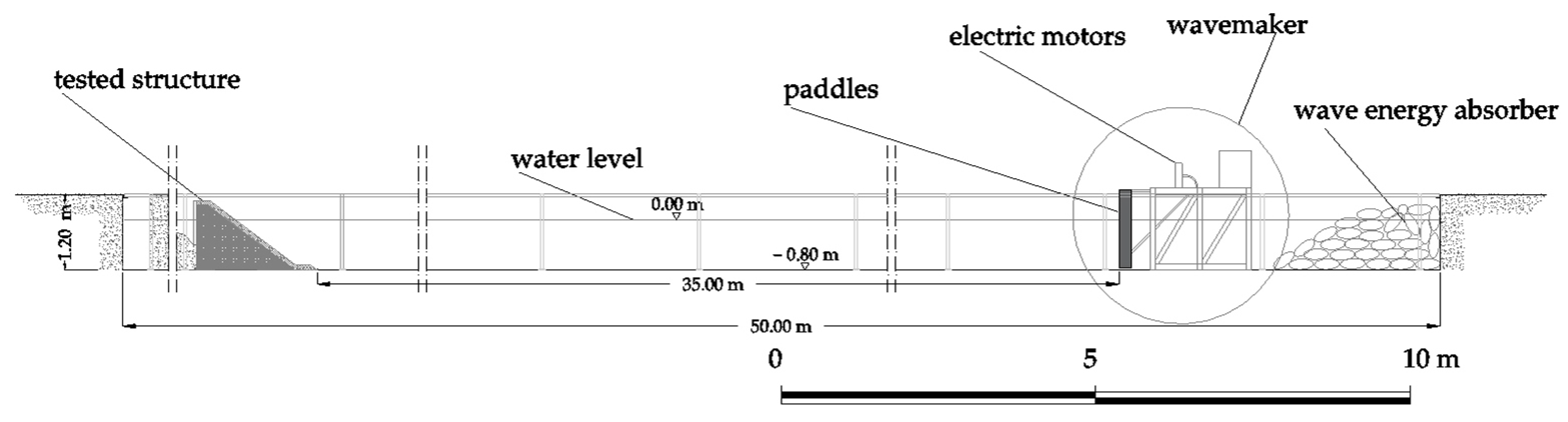
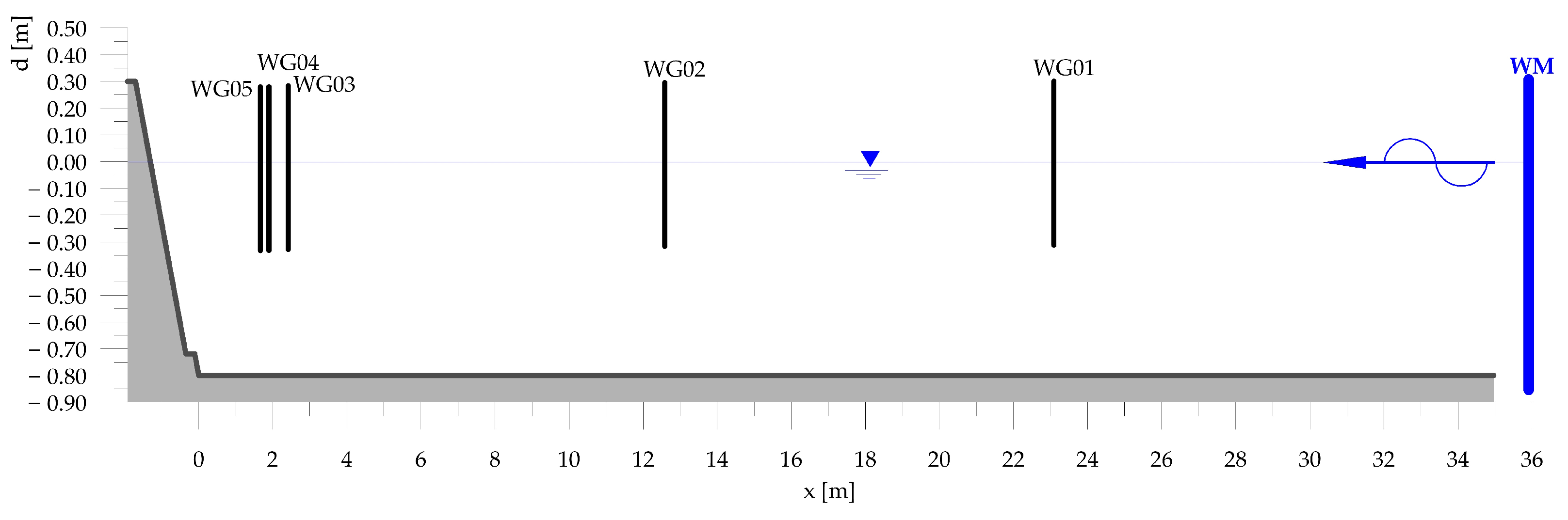
2.1. Experimental Setup

Physical modeling is recognized as a valuable tool to investigate wave propagation (i.e., [56]) and fluid–structure interaction (i.e., [57]). The interactions between waves and long trunk sections are usually investigated with 2D laboratory models, whereas 3D models are required in cases of oblique waves and for the analysis of specific features of the structures (e.g., roundheads) [58,59].
All the experiments illustrated hereinafter were performed in a wave flume at the Coastal Engineering Laboratory (LIC) of the Polytechnic University of Bari (Italy). The wave channel is 2.50 m wide, 50.00 m long, and 1.20 m deep. It is equipped with a piston-type wave maker. The bottom of the flume is flat and made of smooth concrete, whereas the side walls are metallic and smooth. Crushed stones were placed behind the wave paddles to absorb waves on the rear side of the wave generator.
The Froude scaled model was built with a prototype-to-model ratio equal to 20. The physical model reproduced a vertical wall protected by a rubble-mound structure with a core, an underlayer, and a primary armor realized by a single layer of artificial blocks randomly placed with a rather steep front slope (3V:4H). A toe-protection was deployed at the offshore boundary of the rubble-mound structure to improve the armor layer stability. During all the experiments, the water depth in the channel was kept constant at 0.8 m. The experimental configuration is shown in Figure 1.
The new tested artificial concrete armor unit, hereinafter referred to as MAYA unit, was designed at the Maritime Engineering Division, University of Salerno (MEDUS) to be positioned in a rubble mound breakwater single layer primary armor. The idea started with the analysis of a cube to which the ratio between the external surface and volume was incremented, thus improving the porosity of the armor layer and interlocking effect (Figure 2).
The armor layer consisted of concrete units with a density of 2500 kg / m 3 , an individual mass W = 0.891 kg, and a nominal diameter D n = 72.8 mm. The under-layers were realized using a well-graded sediment mixture: the core layer was constituted by fine gravel with a median size, D n 50 = 8.0 mm and the density was ρ = 2600 kg / m 3 , and the layer material was coarse gravel with a D n 50 = 23.0 mm.
The berm width was set equal to three times the single unit width (a frequently adopted solution for these type of structures), whereas its height was set to 0.3 m above the still water level in order to limit wave overtopping, outside the bounds of the experimental investigation. The size of the MAYA units was selected in order to avoid rocking and displacement in the armor, as the stability of the armor is out of the scope of the study illustrated herein.
Figure 3 shows a cross section of the tested structure.
The free surface elevations time series were collected through a series of resistive wave gauges deployed along the wave flume. The analysis of wave reflection was carried out using the widespread method of Mansarde & Funke [60] for the separation of the incident and reflected waves. For this purpose, a triplet of wave gauges (WG03, WG04, and WG05 shown in Figure 4) was placed in front of the breakwater. Other probes were used to measure the free surface elevation near the generation area (WG01) and in a middle section (WG02). Figure 4 shows a sketch of the experimental layout displaying the positions of the gauges.

2.2. Experimental Tests and Reflection Coefficient Analysis

A series of 42 experimental tests were carried out generating about 1000 waves for each test. The generated time series were synthesized in order to reproduce standard JONSWAP wave spectra.
Six different offshore significant spectral wave heights ( H m 0 ) ranging from 0.1 m to 0.3 m were considered.
To better investigate the influence of the wave period on the reflection phenomena, several peak periods ( T p ) were considered for each significant spectral wave height (Table 1). The largest wave periods were included in the test runs to investigate wave reflection from incident waves that can occur in swell-dominated regions [61,62]. The investigation can then be intended as a parametric analysis aimed to highlight the role of H m 0 and wave (either peak or mean) period upon the reflection behavior of sea walls protected by rubble mound structures.
Indeed, the dependence of the reflection coefficient K r with the main wave parameters, as estimated by performing the reflection analysis on the free surface elevation collected by means of the wave gauges WG03, WG04, WG05 (Figure 4), was assessed. The (bulk) reflection coefficient is defined as the square root of the ratio between the reflected ( E r ) and incident ( E i ) energy as follows:
K r = E r E i = 0 S i ( f ) d f 0 S r ( f ) d f
where S i and S r are the incident and reflected spectra estimated using the Mansard & Funke approach [60].
Table 2 details the experimental parameters in terms of relative water depth ( d / L 0 p ), wave steepness ( H m 0 , t / L 0 p ), wave height and water depth ratio ( H m 0 , t / d ), and surf similarity parameter ( ξ m 1 , 0 ) where d is the toe water depth, H m 0 , t is the incident significant spectral wave height at the structure toe), L 0 p is the offshore wavelength calculated by using the peak wave period, and ξ m 1 , 0 is defined as
ξ m 1 , 0 = tan α 2 π H m 0 , t g T m 1 , 0 2
where T m 1 , 0 = m 1 / m 0 is the spectral energy period; m 1 is the spectral moment of order 1 ; m 0 is the spectral moment of order 0; tan α is the RMB front armor slope.
Table 2 shows that experimental ranges of the ratios d / L 0 p , H m 0 , t / L 0 p , H m 0 , t / d , and ξ m 1 , 0 that were tested in order to investigate the reflection coefficient for the considered configuration for a wide range of incident wave conditions, i.e., for both intermediate and deep waters conditions and for different types of breaking mechanisms.
Figure 5a shows a clear correlation between K r and the peak period as already observed by [50]: the larger the peak wave period is, the higher the reflection coefficient is. Figure 5b reports the relationship between K r and the surf similarity parameter ξ m 1 , 0 . Despite a pronounced dispersion of the experimental data, a high correlation between K r and ξ m 1 , 0 can be observed: the larger the surf similarity parameter is, the higher the reflection coefficient is. The trend of the reflection coefficient values as a function of the wave steepness ( H m 0 , t / L 0 p ) is shown in Figure 5c: the larger the wave steepness is, the lower the reflection coefficient is. It is also evident that the reflection coefficient can be considered independent from wave steepness for values greater than 0.05. Finally, according to Muttray et al. [50], a clear correlation is found between K r and the ratio d / L 0 p (Figure 5d): the larger the relative water depth is, the lower the reflection coefficient is.
The experimental findings were qualitatively compared to the database available from previous works. Experimental points from the present study were then inserted in the large dataset reporting data retrieved from several experimental campaigns exploited by [63]. As expected, it can be observed that the experimental points lay in the region of the diagram assigned to “armor units” and the “rock permeable” structures (Figure 6). Indeed, it is well known that the reflection coefficient depends on the armor layer type (influencing the hydraulic roughness of the front slope), as well as on the (bulk) permeability of the structure [63,64]. It should be noted that the comparison against the database exploited by Zanuttigh and Van der Meer [63] does not allow us to provide information about the role of the (bulk) permeability of the structure, as only the features of the armor layer was analyzed.

3. Results and Discussion

The numerous empirical formulas for the prediction of the reflection coefficient K r of RMBs differ depending on the geometric characteristics of the structure as well as the type of units used for primary armor [46,47,48,49,50].
The most widely used prediction formulas can be classified into two main categories: formulas based on surf similarity parameter [51,64], and relative depth [50].
Nevertheless, Muttray et al. [50] observed that the correlation between K r and the surf similarity parameter is weak in the case of the steep slope of the armor. Since experimental data analysis reveals a strong dependence of K r on both d / L 0 p and ξ m 1 , 0 , as reported in Figure 5, in the present work, both approaches were followed.
Firstly, the linear wave reflection approach adopted by Muttray et al. [50] was investigated considering that the dependence of K r on the ratio d / L 0 p is noticeable (Figure 5d).
Muttray et al. carried out experimental trials on RMBs characterized by an ACCROPO-DES™ primary armor slope equal to 2:3, with non-breaking waves (due to the foreshore), and in the absence of overtopping phenomena (Table 3). All these conditions are comparable to the present experimental setup, except for the armor slope.
Several studies have dealt with the testing of the Muttray et al. formula by changing experimental conditions. In particular, Calabrese et al. [65] carried out tests with ECOPODES™ armored RMB with two different front slopes: (i) a slope of 2:3 (as the Muttray et al. experiments [50]); (ii) a slope of 3:4 (equal to that in the present paper).
Calabrese et al. also extended the experimental range of the surf similarity parameter ξ m 1 , 0 , which, in the experiments of Muttray et al. [50], was set greater than 6 (Table 3), and rewrote Muttray’s et al. formula as follows:
K r = 1 A ( m ) + B ( m ) 2 π d L 0 p
where m = t g α is the RMB armor slope, and A and B are two coefficients that depend on m.
Buccino et al. [49] further refined the estimation of A ( m ) and B ( m ) coefficients providing new values (Table 4). These coefficients were estimated fitting the experimental data of K r obtaining the best values of the coefficient of determination ( R 2 ) and standard deviation ( σ ) between measured and predicted K r .
Figure 7 shows the comparison of the present experimental results with the curves by Muttray et al. (named as “M 2:3”) and Buccino et al. with a slope of 2:3 (named as “B 2:3”), and Buccino et al. with a slope of 3:4 (named as “B 3:4”).
Figure 7 reports that the B 3:4 curve is above the B 2:3 curve, since the greater the slope is, the greater the reflected wave energy is, whereas small deviations of the curves can be found between M 2:3 and B 2:3. Buccino et al. already observed that those differences could be caused by the different scales used in the two experimental campaigns (the scale used by Muttray et al. [50] was larger compared to [49,65]). Furthermore, the experimental ranges of the surf similarity parameter were also different: greater than 6 in [50], 2.5 ÷ 9.5 in [49,65], and finally, the water depth at the toe of the structure in the experiments carried out by [49,65] was deeper than Muttray et al. [50]. Hence, it is evident that the coefficients estimated by [49,50,65] have to be considered as characteristic of the particular type of RMB armor unit and front slope.
The experimental investigation carried out in this work, characterized by wider experimental ranges of both d / L 0 p and ξ m 1 , 0 , represent an extension of previous research studies (as reported in Table 2 and Table 3). On the other hand, it is possible to argue the role of the limited (bulk) permeability of the structure. Figure 7 shows that the experimental data of the present study lie above B 3 : 4 curve, preserving the shape. The figure also shows that the reflection coefficient is not influenced by d / L 0 p for values (of the relative water depth) greater than 0.25.
Therefore, restricting the application of Equation (3) to the experimental data of the present study with values of d / L 0 p in the range [ 0 ÷ 0.25 ] , the coefficients A ( m ) and B ( m ) are updated based on the new experimental findings (Table 5). The statistical values, reported in Table 5, confirm a satisfactory fit: R 2 assumes a high value (0.988), both Mean Absolute Error (MAE) and σ are low (0.012 and 0.014, respectively). Figure 8 shows the experimental data of the present work with the theoretical curve of Equation (3), using the refitted coefficients A ( m ) and B ( m ) , i.e., based on the experimental data of the study illustrated herein. Furthermore, in this case, the comparison shows a satisfactory agreement.
The tested structure seems to provide a higher reflection coefficient than RMB tested by Muttray et al. [50] and Buccino et al. [49]. This result is likely due to the presence of the seawall behind the rubble mound structure, the (bulk) permeability, and the novel concrete unit.
More recently, Diaz-Carrasco et al. [66] proposed a new formula to estimate K r in a wider range of variation of the relative water depth [66]. The reflection coefficients are estimated exploiting a sigmoid function depending on the relative water depth and front slope d / ( L tan α ) (Equation (4))
K r = ( K r 1 K r 0 ) 1 + d a L tan α γ 1 + K r 0
where K r 1 and K r 0 are the higher and lower asymptotes of the function, respectively, and a and γ are coefficients representative of the shape of the sigmoid function.
As already observed in other formulas depending on the relative water depth, the sigmoid function must be fitted for each tested front slope, since the lower asymptotic value K r 0 clearly depends on the front slope angle, whereas K r 1 , a, and γ could be considered as constants [66]. Diaz-Carrasco et al. suggested K r 1 = 0.8, a = 0.18 , and γ = 3.5 for all slopes, whereas K r 0 ranges from 0.2 (for a 1:3 slope) to 0.27 (for a 1:1.5 slope) [66].
The K r data observed in the experimental tests carried out in this work were then used to fit Equation (4). Figure 9 shows that the experimental data are well represented by a sigmoid function, and, as expected, the lower asymptotic value K r 0 (=0.30) assumes a higher value than those estimated for milder front slopes. The coefficients a and γ were also refitted (Table 6), and the estimated values are lower than those estimated by Diaz-Carrasco et al. [66].
The influence of the surf similarity parameter upon the reflection coefficient K r was also investigated. Figure 10 shows the measured reflection coefficients represented as a function of the surf similarity parameter ξ m 1 , 0 . The representative curves of the formulas by Zanuttigh and Van der Meer [63] and Seelig and Ahrens [64] refitted by Zanuttigh and Van der Meer [63] are also plotted. It can be observed that both formulas fit well the experimental points.

4. A New Approach to Estimate Reflection Coefficient

The experimental data, as reported in Figure 5, clearly indicate that K r strongly depends on both d / L 0 p and ξ m 1 , 0 . Hence, a more comprehensive approach is proposed herein to involve more than a parameter in K r prediction.
Indeed, within the frame of a general dimensional analysis approach, the reflection coefficient should be expressed as a function of a long series of parameters from which a series of dimensionless groups could be identified (e.g., [58]).
From the example of the application of dimensional analysis, owing to the Buckingham Π theorem (e.g., [58]), the organization of lab runs, and the analysis of experimental data are regulated by dimensionless groups. As shown by Barenblatt [67], it is possible defining similar tests in the laboratory of the same physical phenomenon in which, although the numerical values of the dimensional quantities governing the phenomenon itself are different, the values of the corresponding dimensionless parameters are identical.
Π 1 = f ( Π 2 , Π 3 , . . . , Π i , . . . , Π k )
On the contrary, self-similar solutions are those for which a certain dimensionless parameter can be neglected, as it assumes very small or very large values. In other words, in some phenomena, it may happen that the dependence on an index number vanishes when the latter takes on very large or rather very small values. Barenblatt [67] pointed out that self-similar solutions are called incomplete when the function f tends to 0 or for Π i 0 or Π i . In this case, it is necessary to maintain the dependence on Π i , and therefore, the following equation applies:
Π 1 = f ( Π 2 , Π 3 , . . . , Π i , . . . , Π k ) = f ( Π 2 , Π 3 , . . . , 0 , . . . , Π k ) = Π i α f 1 ( Π 2 , Π 3 , . . . , Π i 1 , Π i + 1 , . . . , Π k )
In Equation (6), the power law with respect to the dimensionless parameter Π i must be also preferred for its simplicity. This is the case of the so-called incomplete self-similarity in the parameter Π i .
For the case at hand, the reflection coefficient can be expressed as a function of the relative water depth and surf similarity parameter as follows:
K r = f ( d / L 0 p , ξ m 1 , 0 )
where the investigation of other parameters (i.e., bulk permeability, porosity of the armor, configuration of the foreshore) is out of the scope of this work, as the aim of the research effort is to address the behavior of a particular kind of structure (i.e., seawalls protected by a rubble mound structure armored with MAYA units).
The formal definition of the functional dependence of K r from the identified dimensionless groups can be a hard and complex task. Indeed, it should depend on physical reasoning (as the formulation proposed by Diaz-Carrasco et al. [66]) and must reveal the main feature of the phenomenon to be described.
Based on an in-depth sensitivity analysis, the reflection coefficient is proposed to be estimated by a power law as follows:
K r = C d L 0 p a ξ m 1 , 0 b
where the parameters were estimated by means of a non-linear least square method: C = 0.1381 (with a 0.95 confidence interval ± 0.020 ), a = 0.1810 (with a 0.95 confidence interval ± 0.104 ), and b = 0.5035 (with a 0.95 confidence interval ± 0.162 ). The inspection of the parameters’ value reveals that the higher the relative water depth and the lower the surf similarity parameter are, the lower the reflection coefficient is. Furthermore, it can be observed that the role of the surf similarity parameter is larger if compared to the role of relative water depth.
Equation (8) was tested against other widely used formulas for the estimation of the reflection coefficient, which take into account the dependence of K r from the surf similarity parameter ξ m 1 , 0 [63,64] and the relative water depth [66]. Figure 11 shows a satisfactory agreement between the experimental points and those calculated using Equation (8), as also confirmed by the accuracy assessment estimated using the statistical parameters reported in Table 7.
Since the coefficient of determination R 2 is insensitive to additive and proportional differences between the predicted and observed data, an additional statistical parameter, the Nash–Sutcliffe coefficient of efficiency (NSE), was exploited to assess the performance of the proposed formula (e.g., [68]). The NSE is defined as the ratio of the mean square error to the variance in the observed data subtracted from unity and ranges from minus infinity to 1.0. Given that the higher the values of NSE are, the better the agreement is, four model performance classes have been proposed by Ritter & Munoz-Carpena [68]: unsatisfactory (NSE ≤ 0.65), acceptable (NSE = 0.65–0.8), Good (NSE = 0.8–0.9) and Very good (NSE≥ 0.9).
A comparative analysis of the statistical parameters, shown in Table 7, reveals that, although the existing equations based on the Iribarren parameter could be also used for providing reflection coefficient values for the tested structure, their performances are lower than those of the Equation (8). The formula proposed by Diaz-Carrasco et al. [66] provides the best results, but the coefficient in the equation needs fitting for each front slope, as the lower asymptotic value of the reflection coefficient ( K r 0 ) depends on the front slope. Hence, the proposed approach can be used without further parameter estimation for seawalls protected by a rubble mound structure for a relative water depth in the range [0.042÷0.709] and surf similarity parameters ( ξ m 1 , 0 ) in the range [2.91÷11.91].

5. Concluding Remarks

This paper aims to investigate the wave reflection of a rubble mound structure used to protect a vertical concrete seawall. A novel concrete unit was used to armor the primary layer, and a well-graded sediment mixture was used to deploy core and filter layers. The behavior of the structure in terms of reflection coefficient was investigated by performing several experimental trials that prove the following observations:
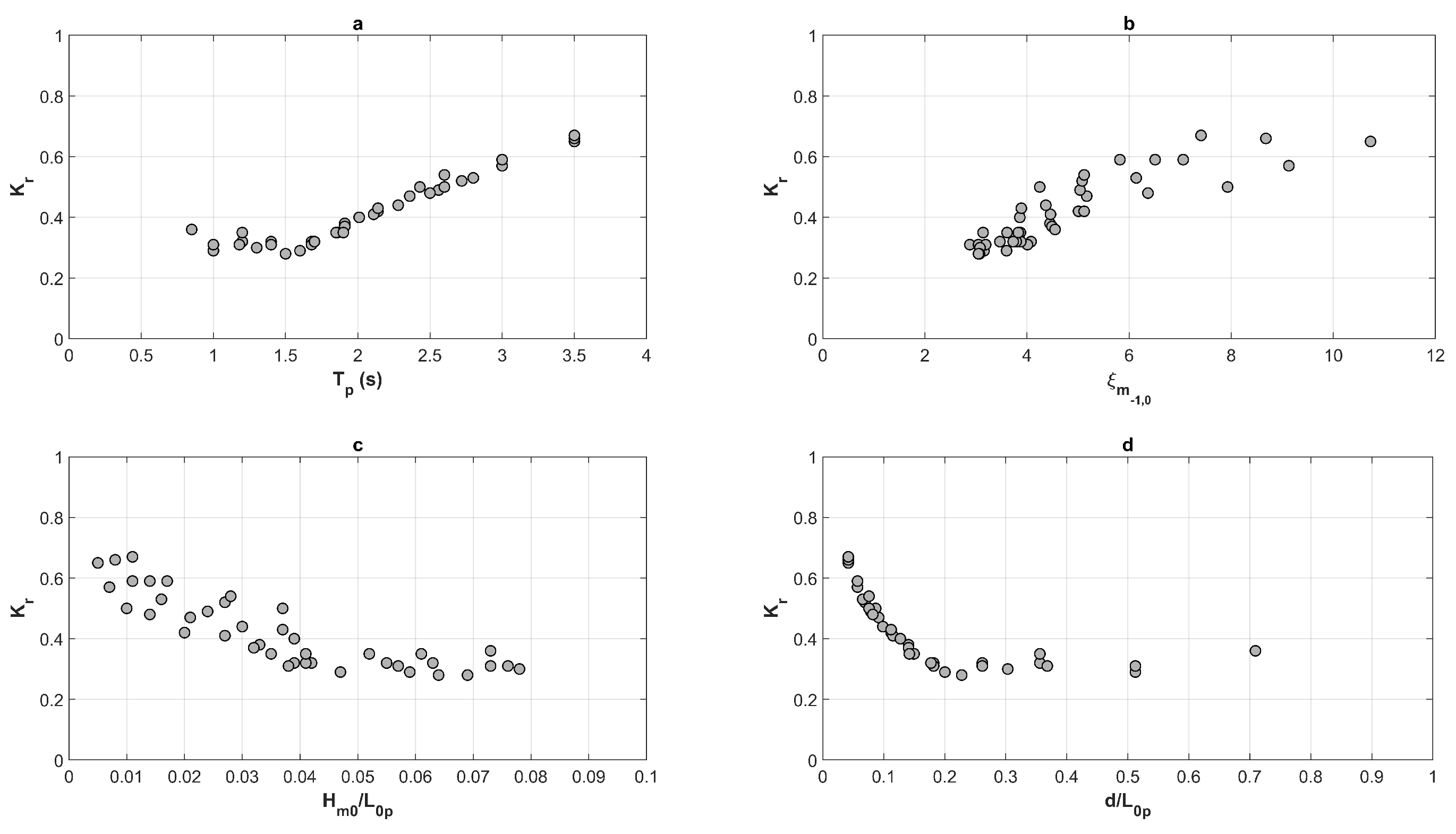
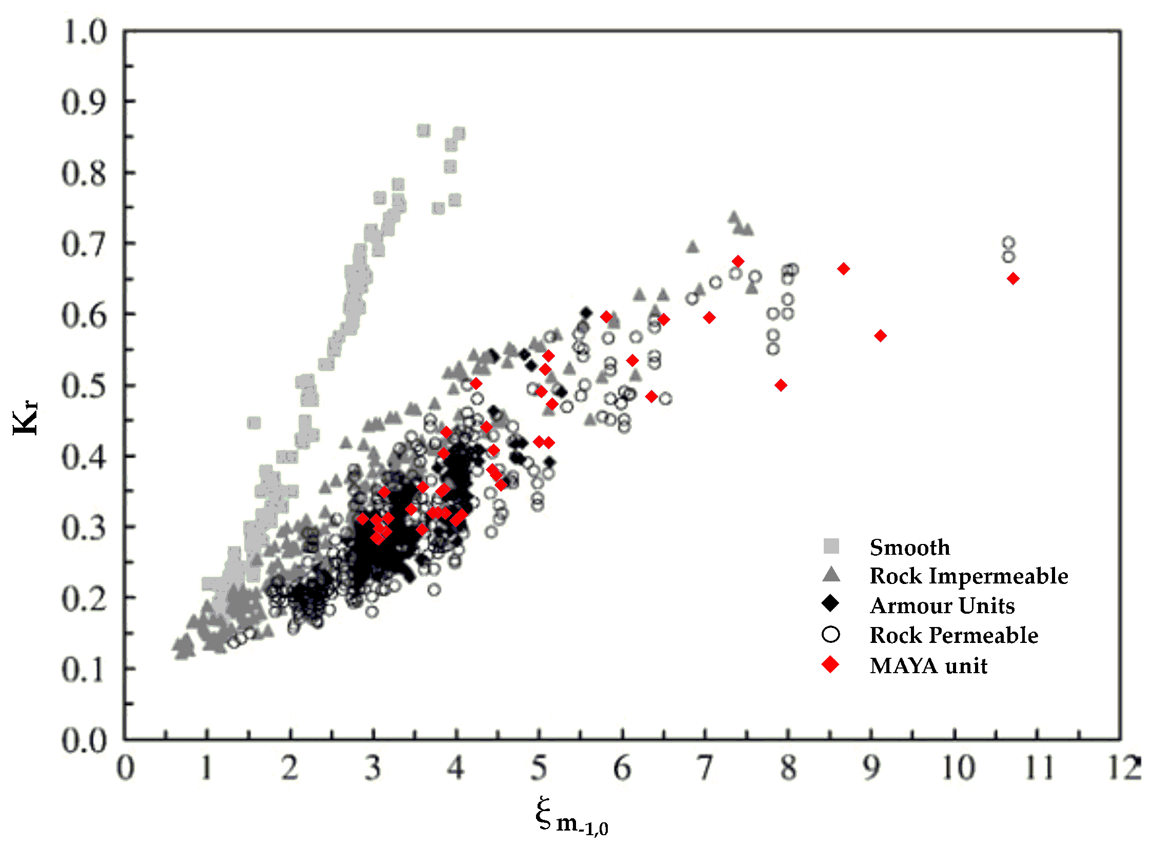
  • The influence of the main wave parameters upon the estimated reflection coefficients shows, at least qualitatively, the expected big picture: the larger the peak wave period is, the larger the surf similarity parameter is, the lower the wave steepness is, and the lower the relative water depth is, the larger the reflection coefficient will be;
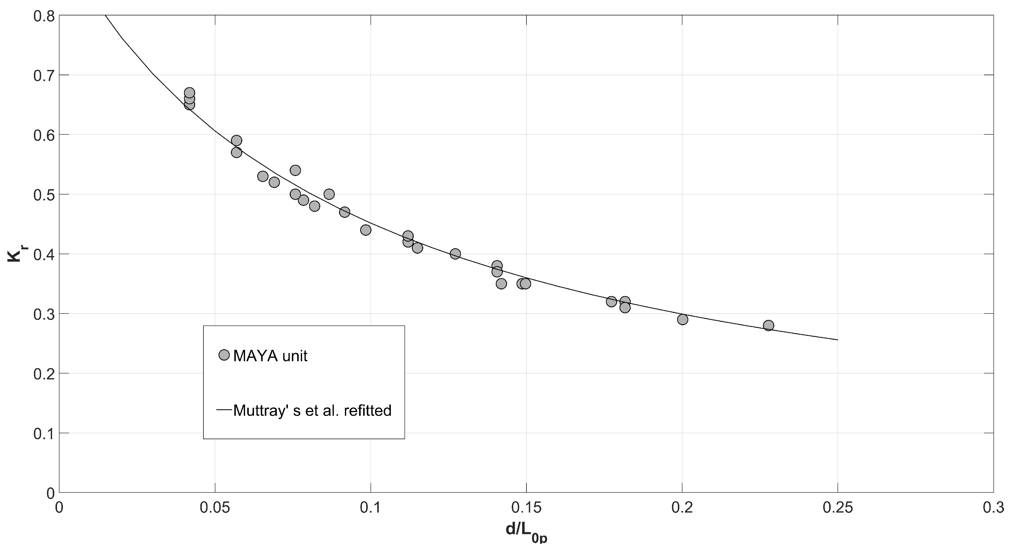
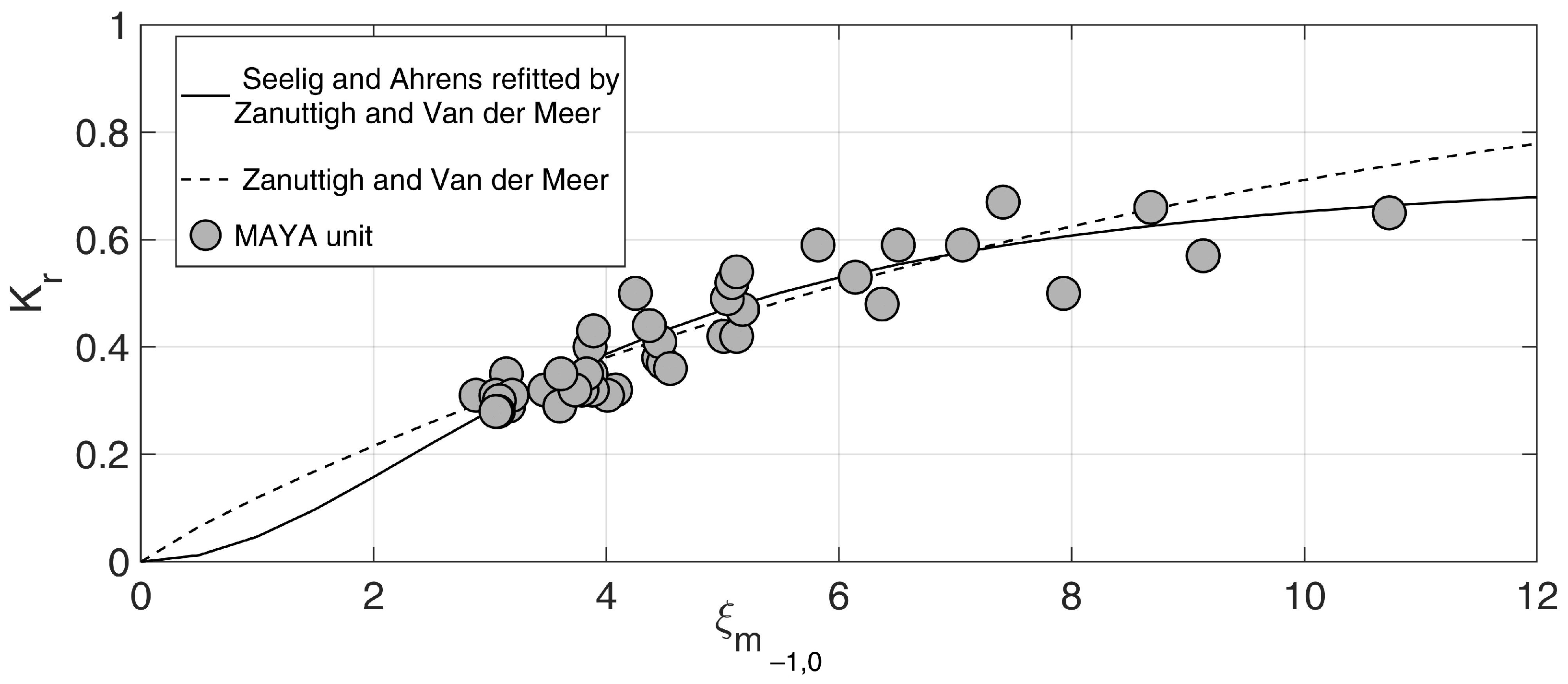
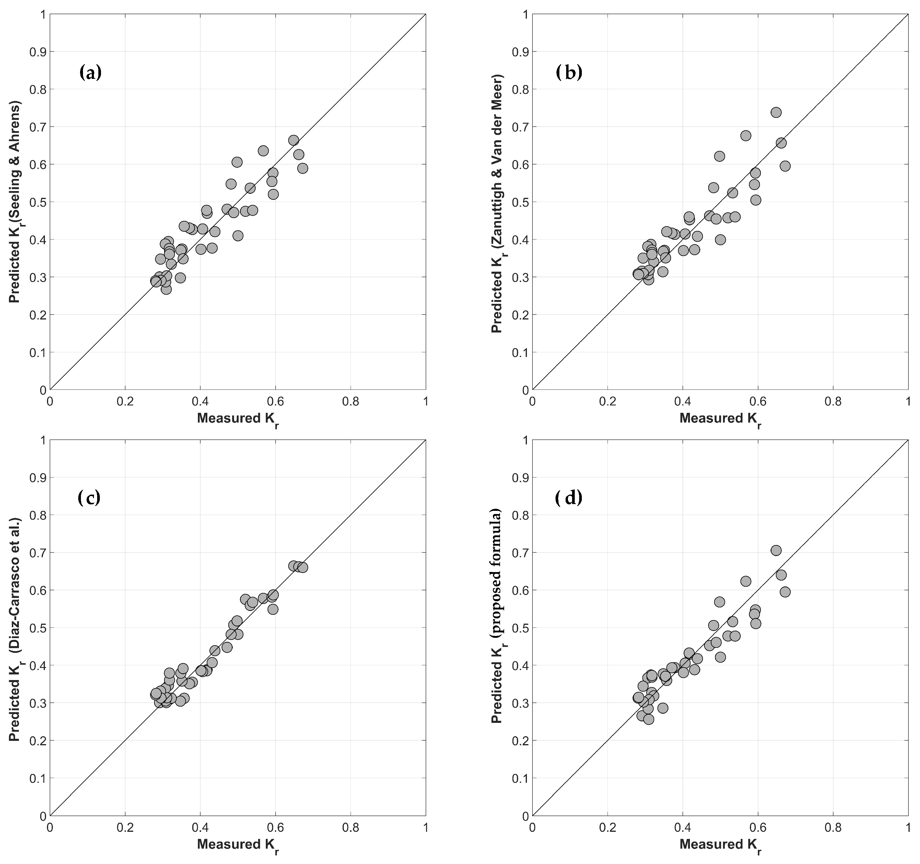
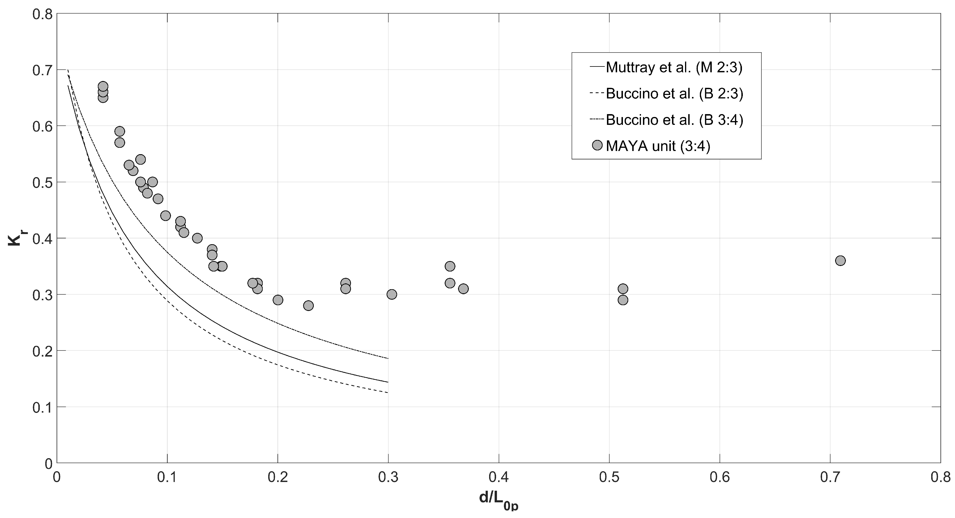
  • The modeled structure has a more reflective behavior with respect to conventional rubble mound breakwaters, likely due to the presence of the vertical seawall influencing the (bulk) porosity. Widespread empirical formulations were then used, after refitting the empirical parameters, and a satisfactory agreement was obtained.
Nevertheless, in order to avoid the need for the refitting procedure, a novel empirical formulation was proposed with the following features:
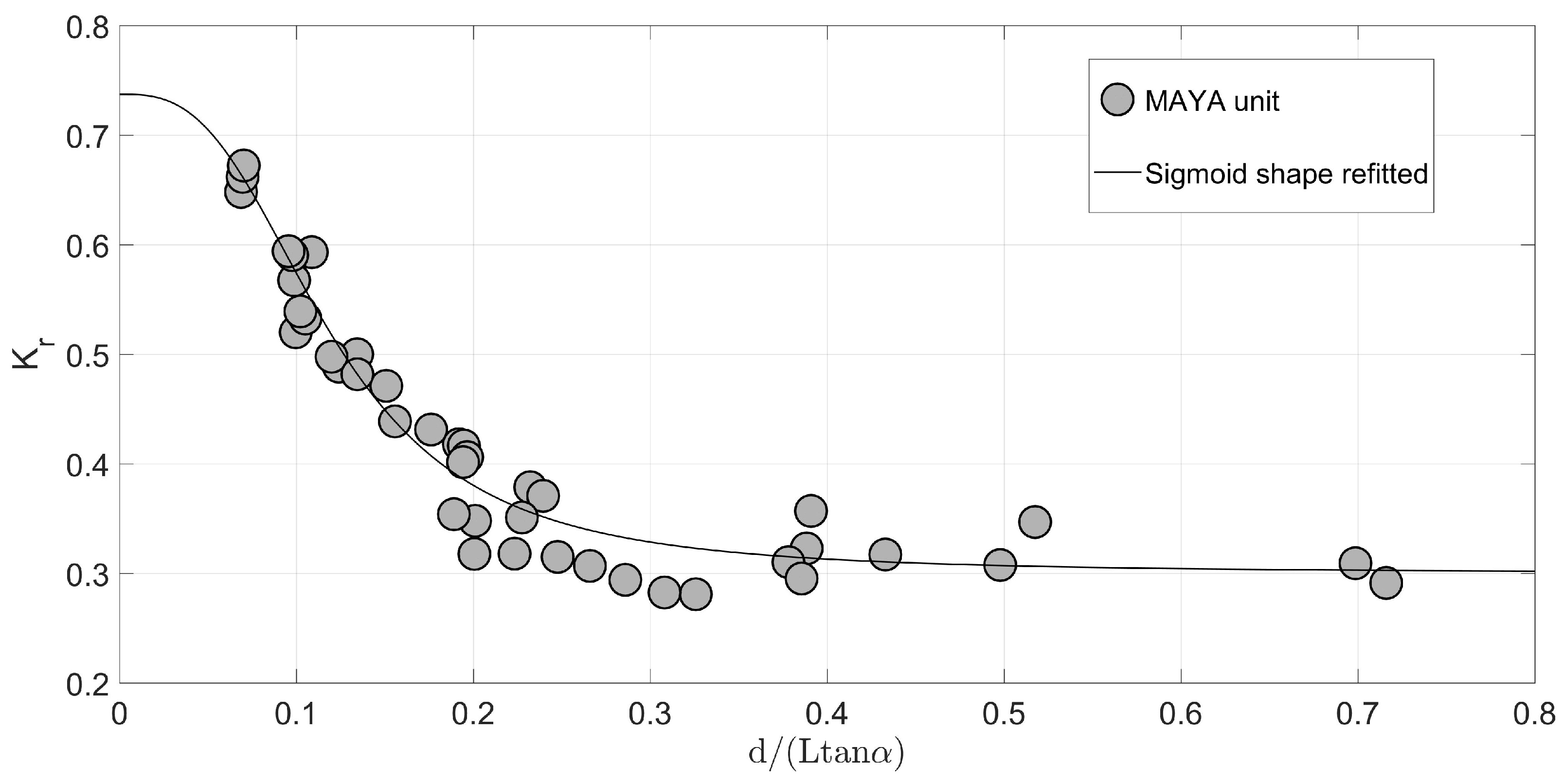
  • It relies on the hypothesis that both the relative water depth (ratio between the water depth and the peak wavelength at the toe of the structure) and the surf similarity parameter (computed by using the spectral wave height at the toe of the structures and the spectral mean period) influence the reflection coefficient. The fitting procedure confirmed that both the dimensionless parameters cannot be neglected in the case at hand. Indeed, the inspection of the value of the estimated parameters reveals that the role of the surf similarity parameter is larger if compared to the role of relative water depth: the higher the relative water depth and the lower the surf similarity parameter are, the lower the reflection coefficient is;
  • It provides a reliable prediction of the reflection coefficient without further parameter estimation, for seawalls protected by rubble mound structures and for a relative water depth in the range [0.042 ÷ 0.709] and a surf similarity parameter in the range [2.91 ÷ 11.91].
More experimental trials are planned to investigate the stability of the novel armor unit and the wave overtopping discharge under extreme wave conditions to provide further design guidelines for seawalls protected by rubble mounds breakwaters.

Author Contributions

Conceptualization, L.P., A.R., M.G.M., M.F.B., and F.D.; methodology, L.P., A.R., M.G.M., M.F.B., and M.M.; software, L.P., A.R., M.G.M., M.F.B., and D.P.; validation, L.P., A.R., and M.G.M.; formal analysis, L.P., A.R., M.G.M., M.F.B., and M.M.; investigation, L.P., A.R., M.G.M., M.F.B., and D.P.; resources, L.P., A.R., M.G.M., M.F.B., and D.P.; data curation, L.P., A.R., M.G.M., and M.F.B.; writing—original draft preparation, L.P., M.G.M., and M.F.B.; writing—review and editing, L.P., A.R., M.G.M., M.F.B., D.P., F.D., and M.M.; visualization, L.P., A.R., M.G.M., M.F.B., and D.P.; supervision, M.M.; project administration, L.P.; funding acquisition, M.M. All authors have read and agreed to the published version of the manuscript.

Funding

This research received no external funding.

Institutional Review Board Statement

Not applicable.

Informed Consent Statement

Not applicable.

Data Availability Statement

To gain access to the experimental data, please contact the authors.

Conflicts of Interest

The authors declare no conflict of interest.

References

  1. Di Risio, M.; Bruschi, A.; Lisi, I.; Pesarino, V.; Pasquali, D. Comparative analysis of coastal flooding vulnerability and hazard assessment at national scale. J. Mar. Sci. Eng. 2017, 5, 51. [Google Scholar] [CrossRef] [Green Version]
  2. Bruno, M.F.; Molfetta, M.G.; Pratola, L.; Mossa, M.; Nutricato, R.; Morea, A.; Nitti, D.O.; Chiaradia, M.T. A combined approach of field data and earth observation for coastal risk assessment. Sensors 2019, 19, 1399. [Google Scholar] [CrossRef] [Green Version]
  3. Archetti, R.; Damiani, L.; Bianchini, A.; Romagnoli, C.; Abbiati, M.; Addona, F.; Airoldi, L.; Cantelli, L.; Gaeta, M.G.; Guerrero, M.; et al. Innovative strategies, monitoring and analysis of the coastal erosion risk: The stimare project. In Proceedings of the 29th International Ocean and Polar Engineering Conference, Honolulu, HI, USA, 16–21 June 2019; Volume 3, pp. 3836–3841. [Google Scholar]
  4. Bruno, M.F.; Saponieri, A.; Molfetta, M.G.; Damiani, L. The DPSIR approach for coastal risk assessment under climate change at regional scale: The case of apulian coast (Italy). J. Mar. Sci. Eng. 2020, 8, 531. [Google Scholar] [CrossRef]
  5. Pasquali, D.; Marucci, A. The effects of urban and economic development on coastal zone management. Sustainability 2021, 13, 6071. [Google Scholar] [CrossRef]
  6. Silvester, R. Wave reflection at sea walls and breakwaters. Proc. Inst. Civ. Eng. 1972, 51, 123–131. [Google Scholar]
  7. Mallayachari, V.; Sundar, V. Reflection characteristics of permeable seawalls. Coast. Eng. 1994, 23, 135–150. [Google Scholar] [CrossRef]
  8. Saponieri, A.; Di Risio, M.; Pasquali, D.; Valentini, N.; Aristodemo, F.; Tripepi, G.; Celli, D.; Streicher, M.; Damiani, L. Beach profile evolution in front of storm seawalls: A physical and numerical study. Coast. Eng. Proc. 2018, 36, 70. [Google Scholar] [CrossRef]
  9. Salauddin, M.; Pearson, J. Wave overtopping and toe scouring at a plain vertical seawall with shingle foreshore: A Physical model study. Ocean Eng. 2019, 171, 286–299. [Google Scholar] [CrossRef] [Green Version]
  10. Koraim, A.; Heikal, E.; Zaid, A.A. Hydrodynamic characteristics of porous seawall protected by submerged breakwater. Appl. Ocean Res. 2014, 46, 1–14. [Google Scholar] [CrossRef]
  11. Mettam, J.; Berry, J. Factors of safety for the design of breakwaters. In Coastal Engineering 1982; ASCE: Reston, VA, USA, 1982; pp. 2097–2106. [Google Scholar]
  12. Di Risio, M.; Lisi, I.; Beltrami, G.M.; De Girolamo, P. Physical modeling of the cross-shore short-term evolution of protected and unprotected beach nourishments. Ocean Eng. 2010, 37, 777–789. [Google Scholar] [CrossRef]
  13. Celli, D.; Li, Y.; Ong, M.C.; Di Risio, M. The role of submerged berms on the momentary liquefaction around conventional rubble mound breakwaters. Appl. Ocean Res. 2019, 85, 1–11. [Google Scholar] [CrossRef]
  14. Molines, J.; Centi, R.; Di Risio, M.; Medina, J.R. Estimation of layer coefficients of cubipod homogeneous low-crested structures using physical and numerical model placement tests. Coast. Eng. 2021, 168, 103901. [Google Scholar] [CrossRef]
  15. Celli, D.; Pasquali, D.; De Girolamo, P.; Di Risio, M. Effects of submerged berms on the stability of conventional rubble mound breakwaters. Coast. Eng. 2018, 136, 16–25. [Google Scholar] [CrossRef]
  16. Celli, D.; Li, Y.; Ong, M.C.; Di Risio, M. Random wave-induced momentary liquefaction around rubble mound breakwaters with submerged berms. J. Mar. Sci. Eng. 2020, 8, 338. [Google Scholar] [CrossRef]
  17. Kobayashi, N.; Wurjanto, A. Wave transmission over submerged breakwaters. J. Waterw. Port Coast. Ocean. Eng. 1989, 115, 662–680. [Google Scholar] [CrossRef]
  18. Rojanakamthorn, S.; Isobe, M.; Watanabe, A. A mathematical model of wave transformation over a submerged breakwater. Coast. Eng. Jpn. 1989, 32, 209–234. [Google Scholar] [CrossRef]
  19. Anton, I.A.; Panaitescu, M.; Panaitescu, F.V.; Ghiţă, S. Impact of coastal protection systems on marine ecosystems. In E3S Web of Conferences; EDP Sciences: Les Ulis, France, 2019; Volume 85, p. 07011. [Google Scholar]
  20. Dattatri, J.; Raman, H.; Shankar, N.J. Performance characteristics of submerged breakwaters. In Coastal Engineering 1978; ASCE: Reston, VA, USA, 1978; pp. 2153–2171. [Google Scholar]
  21. Abdul Khader, M.I.; Rai, S. A study of submerged breakwaters. J. Hydraul. Res. 1980, 18, 113–121. [Google Scholar] [CrossRef]
  22. Requejo, S.; Vidal, C.; Losada, I. Modelling of wave loads and hydraulic performance of vertical permeable structures. Coast. Eng. 2002, 46, 249–276. [Google Scholar] [CrossRef]
  23. Dalrymple, R.; Losada, M.A.; Martin, P. Reflection and transmission from porous structures under oblique wave attack. J. Fluid Mech. 1991, 224, 625–644. [Google Scholar] [CrossRef]
  24. Van der Meer, J.W.; Daemen, I.F. Stability and wave transmission at low-crested rubble-mound structures. J. Waterw. Port Coast. Ocean. Eng. 1994, 120, 1–19. [Google Scholar] [CrossRef]
  25. Eldrup, M.R.; Lykke Andersen, T.; Burcharth, H.F. Stability of rubble mound breakwaters—A study of the notional permeability factor, based on physical model tests. Water 2019, 11, 934. [Google Scholar] [CrossRef] [Green Version]
  26. Van der Meer, J.W.; Pilarczyk, K.W. Stability of low-crested and reef breakwaters. In Coastal Engineering 1990; ASCE: Reston, VA, USA, 1991; pp. 1375–1388. [Google Scholar]
  27. De Rouck, J.; Van Damme, L. Overall slope stability analysis of rubble mound breakwaters. In Coastal Engineering 1996; ASCE: Reston, VA, USA, 1997; pp. 1603–1616. [Google Scholar]
  28. Bux, I. The Effects of Foreshore Slope on Breakwater Armour Unit Stability. Master’s Thesis, UNESCO-IHE Institute for Water Education, Delft, The Netherlands, 2007. [Google Scholar]
  29. Mousavi, S.H.; Kavianpour, M.; Aminoroayaie Yamini, O. Experimental analysis of breakwater stability with antifer concrete block. Mar. Georesour. Geotechnol. 2017, 35, 426–434. [Google Scholar] [CrossRef]
  30. Fabião, J.; Teixeira, A.T.; Araújo, M. Hydraulic stability of tetrapod armour layers. Physical model study. In Proceedings of the 6th International Short Course/Conference on Applied Coastal Research, Lisbon, Portugal, 4–7 June 2013; Available online: http://scacr.eu/6th-scacr-2013/ (accessed on 6 August 2021).
  31. Giraudel, C.; Garcia, N.; Ledoux, S. Single-layer breakwater armouring: Feedback on the accropode technology from site experience. In Coastal Engineering 2014; ASCE: Reston, VA, USA, 2014; p. 34. [Google Scholar]
  32. Muttray, M.; ten Oever, E.; Reedijk, B. Stability of low crested and submerged breakwaters with single layer armouring. J. Shipp. Ocean. Eng. 2012, 2, 140–152. [Google Scholar]
  33. Herrera, M.P.; Gómez-Martín, M.E.; Medina, J.R. Hydraulic stability of rock armors in breaking wave conditions. Coast. Eng. 2017, 127, 55–67. [Google Scholar] [CrossRef]
  34. Dick, T.M.; Brebner, A. Solid and permeable submerged breakwaters. In Coastal Engineering 1968; ASCE: Reston, VA, USA, 1969; pp. 1141–1158. [Google Scholar]
  35. Isaacson, M.; Papps, D.; Mansard, E. Oblique reflection characteristics of rubble-mound structures. J. Waterw. Port Coast. Ocean. Eng. 1996, 122, 1–7. [Google Scholar] [CrossRef]
  36. Zhao, H.; Liang, Z.; Jeng, D.S.; Zhu, J.; Guo, Z.; Chen, W. Numerical investigation of dynamic soil response around a submerged rubble mound breakwater. Ocean Eng. 2018, 156, 406–423. [Google Scholar] [CrossRef]
  37. Pasquali, D.; Di Risio, M.; De Girolamo, P. A simplified real time method to forecast semi-enclosed basins storm surge. Estuar. Coast. Shelf Sci. 2015, 165, 61–69. [Google Scholar] [CrossRef]
  38. Muis, S.; Verlaan, M.; Winsemius, H.C.; Aerts, J.C.J.H.; Ward, P.J. A global reanalysis of storm surges and extreme sea levels. Nat. Commun. 2016, 7, 11969. [Google Scholar] [CrossRef] [PubMed] [Green Version]
  39. Pasquali, D.; Bruno, M.F.; Celli, D.; Damiani, L.; Di Risio, M. A simplified hindcast method for the estimation of extreme storm surge events in semi-enclosed basins. Appl. Ocean Res. 2019, 85, 45–52. [Google Scholar] [CrossRef]
  40. Losada, M.; Kobayashi, N.; Martín, F.L. Armor stability on submerged breakwaters. J. Waterw. Port Coast. Ocean. Eng. 1992, 118, 207–212. [Google Scholar] [CrossRef]
  41. Lin, P.; Karunarathna, S. Numerical study of solitary wave interaction with porous breakwaters. J. Waterw. Port Coast. Ocean. Eng. 2007, 133, 352–363. [Google Scholar] [CrossRef] [Green Version]
  42. Cao, Y.; Jiang, C.; Bai, Y. Wave attenuation properties of double trapezoidal submerged breakwaters on flat-bed. Trans. Tianjin Univ. 2012, 18, 401–410. [Google Scholar] [CrossRef]
  43. Bakker, P.; van den Berge, A.; Hakenberg, R.; Klabbers, M.; Muttray, M.; Reedijk, B.; Rovers, I. Development of concrete breakwater Armour Units. In Proceedings of the 1st Coastal Estuary and Offshore Engineering Specialty Conference of the Canadian Society for Civil Engineering, Moncton, NB, Canada, 4–7 June 2003. [Google Scholar]
  44. Iribarren, R. Una Fórmula Para el cálculo de los Diques de Escollera; Ed. M. Bermejillo Usabiaga: Pasajes, Spain, 1938. [Google Scholar]
  45. Hudson, R.Y. Laboratory investigation of rubble-mound breakwaters. Trans. Am. Soc. Civ. Eng. 1961, 126, 492–520. [Google Scholar] [CrossRef]
  46. Losada, M.A.; Gim nez Curto, L.A. Flow characteristics on rough, permeable slopes under wave action. Coast. Eng. 1980, 4, 187–206. [Google Scholar] [CrossRef]
  47. Allsop, N. Reflection performance of rock armoured slopes in random waves. In Coastal Engineering 1990; ASCE: Reston, VA, USA, 1991; pp. 1460–1472. [Google Scholar]
  48. Zanuttigh, B.; Formentin, S.M.; Briganti, R. A neural network for the prediction of wave reflection from coastal and harbor structures. Coast. Eng. 2013, 80, 49–67. [Google Scholar] [CrossRef]
  49. Buccino, M.; Calabrese, M.; Ciardulli, F.; Di Pace, P.; Tomasicchio, G. One layer concrete armor units with a rock-like skin: Wave reflection and run-up. J. Coast. Res. 2011, SI 64, 469–473. [Google Scholar]
  50. Muttray, M.; Oumeraci, H.; Oever, E.T. Wave reflection and wave run-up at rubble mound breakwaters. In Coastal Engineering 2006; World Scientific: Singapore, 2007; pp. 4314–4324. [Google Scholar]
  51. Zanuttigh, B.; Van der Meer, J.W. Wave reflection from coastal structures. In Coastal Engineering 2006; World Scientific: Singapore, 2007; pp. 4337–4349. [Google Scholar]
  52. DELOS Project. Available online: http://www.delos.unibo.it (accessed on 6 August 2021).
  53. CLASH Project. Available online: http://www.clash-eu.org (accessed on 6 August 2021).
  54. Van der Meer, J.; Allsop, N.; Bruce, T.; De Rouck, J.; Kortenhaus, A.; Pullen, T.; Schüttrumpf, H.; Troch, P.; Zanuttigh, B. EurOtop: Manual on Wave Overtopping of Sea Defences and Related Structures: An Overtopping Manual Largely Based on European Research, but for Worldwide Application, 2nd ed. 2018. Available online: http://www.overtopping-manual.com/ (accessed on 6 August 2021).
  55. Guo, Y.; Mohapatra, S.; Guedes Soares, C. Composite breakwater of a submerged horizontal flexible porous membrane with a lower rubble mound. Appl. Ocean Res. 2020, 104, 102371. [Google Scholar] [CrossRef]
  56. Molfetta, M.G.; Bruno, M.F.; Pratola, L.; Rinaldi, A.; Morea, A.; Preziosa, G.; Pasquali, D.; Risio, M.D.; Mossa, M. A sterescopic system to measure water waves in laboratories. Remote Sens. 2020, 12, 2288. [Google Scholar] [CrossRef]
  57. Aristodemo, F.; Di Risio, M. Wave-structure interaction processes in coastal engineering. Water 2021, 13, 831. [Google Scholar] [CrossRef]
  58. Hughes, S.A. Physical Models and Laboratory Techniques in Coastal Engineering; World Scientific: Singapore, 1993; Volume 7. [Google Scholar]
  59. Wolters, G.; van Gent, M.; Allsop, W.; Hamm, L.; Muhlestein, D. HYDRALAB III: Guidelines for physical model testing of rubble mound breakwaters. In Coasts, Marine Structures and Breakwaters: Adapting to Change; Thomas Telford Ltd.: London, UK, 2010; pp. 559–670. [Google Scholar]
  60. Mansard, E.P.; Funke, E. The measurement of incident and reflected spectra using a least squares method. In Coastal Engineering 1980; ASCE: Reston, VA, USA, 1980; pp. 154–172. [Google Scholar]
  61. Thompson, W.C.; Nelson, A.R.; Sedivy, D.G. Wave group anatomy of ocean wave spectra. In Coastal Engineering 1984; ASCE: Reston, VA, USA, 1985; pp. 661–677. [Google Scholar]
  62. Bruno, M.F.; Molfetta, M.G.; Totaro, V.; Mossa, M. Performance Assessment of ERA5 Wave Data in a Swell Dominated Region. J. Mar. Sci. Eng. 2020, 8, 214. [Google Scholar] [CrossRef] [Green Version]
  63. Zanuttigh, B.; van der Meer, J.W. Wave reflection from coastal structures in design conditions. Coast. Eng. 2008, 55, 771–779. [Google Scholar] [CrossRef]
  64. Seelig, W.N.; Ahrens, J.P. Estimation of Wave Reflection and Energy Dissipation Coefficients for Beaches, Revetments, and Breakwaters; Technical Paper 81-1; Coastal Engineering Research Center: Fort Belvoir VA, USA, 1981. [Google Scholar]
  65. Calabrese, M.; Buccino, M.; Ciardulli, F.; Di Pace, P.; Tomasicchio, R.; Vicinanza, D. Wave run-up and reflection at rubble mound breakwaters with ecopode armor layer. Coast. Eng. Proc. 2011, 1, 45. [Google Scholar] [CrossRef] [Green Version]
  66. Díaz-Carrasco, P.; Eldrup, M.R.; Andersen, T.L. Advance in wave reflection estimation for rubble mound breakwaters: The importance of the relative water depth. Coast. Eng. 2021, 168, 103921. [Google Scholar] [CrossRef]
  67. Barenblatt, G.I. Dimensional Analysis; CRC Press: Boca Raton, FL, USA, 1987. [Google Scholar]
  68. Ritter, A.; Muñoz-Carpena, R. Performance evaluation of hydrological models: Statistical significance for reducing subjectivity in goodness-of-fit assessments. J. Hydrol. 2013, 480, 33–45. [Google Scholar] [CrossRef]
Figure 1. Wave flume setup: channel dimensions, water depth, wave board, and structure location for run tests.
Jmse 09 00937 g001
Figure 2. MAYA armor unit: 1:20 scale model (a), armor layer (b), and isometric views in different orientation (c).
Jmse 09 00937 g002
Figure 3. A cross section of the RMB model with MAYA mass unit.
Jmse 09 00937 g003
Figure 4. Wave gauge positions along the channel.
Jmse 09 00937 g004
Figure 5. Reflection coefficient K r as a function of peak period T p (a), surf similarity parameter ξ m 1 , 0 (b), offshore wave steepness H m 0 , t / L 0 p (c), and d / L 0 p (d).
Jmse 09 00937 g005
Figure 6. Experimental data included in the wave reflection database exploited by Zanuttigh and Van der Meer. Maya units are identified by red diamonds (adapted from [63]).
Jmse 09 00937 g006
Figure 7. Dependence of reflection coefficient K r from d / L 0 p .
Jmse 09 00937 g007
Figure 8. Muttray’s formula refitted using experimental data.
Jmse 09 00937 g008
Figure 9. Comparison of MAYA armor units with the refitted sigmoid function.
Jmse 09 00937 g009
Figure 10. Comparison of MAYA armor units with the curves by Seelig and Ahrens refitted by Zanuttigh and Van der Meer (solid line) and Zanuttigh and Van der Meer (dotted line).
Jmse 09 00937 g010
Figure 11. Comparison of predicted and measured reflection coefficient provided by (a) Seelig and Ahrens [64], (b) Zanuttigh and Van der Meer [63], (c) Diaz-Carrasco et al. [66], and (d) the proposed formula.
Jmse 09 00937 g011
Table 1. List of the wave conditions tested in the LIC channel.
Test SeriesNumber of Tests Conducted H m 0 (m) T p (s)
A60.100.85–3.50
B120.151.00–3.50
C90.201.18–3.50
D80.251.30–3.00
E70.301.50–2.72
Table 2. Overview of the geometrical and wave parameters tested in the experimental layout.
d (m) d / L 0 p H m 0 , t / L 0 p H m 0 , t / d ξ m 1 , 0
MinMaxMinMaxMinMaxMinMax
0.80.0420.7090.0040.0660.090.312.91011.910
Table 3. Overview of the geometrical and wave parameters tested by Muttray et al. and Calabrese et al.
d / L 0 p H m 0 , t / L 0 p H m 0 , t / d ξ m 1 , 0
AuthorsMinMaxMinMaxMinMaxMinMax
Muttray et al. [50]0.0500.2300.0050.0530.080.40 6
Calabrese et al. [65]0.0480.3080.0060.0650.090.402.5029.505
Table 4. Coefficients A ( m ) and B ( m ) to be included in Equation (3) refitted by Buccino et al. [49]. Best fit values R 2 and σ are reported for each front slope.
Mass UnitSlope A ( m ) B(m) R 2 σ
ECOPODES2:31.2033.600.9660.014
ECOPODES3:41.3122.1580.9340.020
Table 5. New coefficients A ( m ) and B ( m ) to be included in Equation (3) refitted exploiting the experimental data. Best fit values R 2 , σ , and MAE are also reported.
Mass UnitSlopeA(m)B(m) R 2 σ MAE
MAYA3:41.0861.7960.9880.0140.012
Table 6. Values of the sigmoid function parameters refitted for MAYA units and a 3:4 front slope.
Mass UnitSlope K r 0 K r 1 a γ
MAYA3:40.300.740.122.90
Table 7. Best fit values estimated for the existing formulas and the proposed approach.
Author R 2 σ MAENSE
Seelig and Ahrens [64]0.8220.0500.0410.817 (Good)
Diaz-Carrasco et al. [66] refitted0.9440.0280.0230.943 (Very good)
Proposed formula0.8690.0430.0350.868 (Good)
Publisher’s Note: MDPI stays neutral with regard to jurisdictional claims in published maps and institutional affiliations.

