1. Introduction
Tank heel, or the liquefied natural gas (LNG) volume remaining in the tank before bunkering, is a significant issue in LNG fuel tank design and sump tank optimization. Unlike offshore LNG fuel tanks where the operation has no filling limitation, seagoing LNG units are designed to keep the liquid above a specific filling level. The filling ratio should satisfy the desired filling head to keep the suction pipe submerged in the LNG under operation conditions (DNV RU ship) [
1]. The tank geometry needs to be optimized to increase the usage efficiency of the LNG fuel tank.
Recently, studies on sloshing have increased for the application of LNG fuel tanks [
2,
3,
4]. The most popular methods of sloshing studies are model tests and numerical simulations. Nasar et al. [
5] conducted experiments on the sloshing of a fuel tank to study the phenomena of liquid sloshing in tanks attributed to normal beam waves. Model testing is visual and reliable, but there are some uncontrollable factors in the model tests, such as the capability and accuracy of the equipment.
With advances in computer technology, the numerical method for sloshing analysis has become popular and reliable. Numerical and experimental studies were conducted to dictate the behavior of the free surface motion of the liquid inside the tank under the excitation of a natural frequency [
6]. In numerical analysis, the smoothed particle hydrodynamics (SPH) method was applied to analyze sloshing flow. The results were in good agreement with the experimental method.
Previous studies focused on the effects of sloshing on the tank by adapting the loads and wave conditions [
7,
8,
9,
10,
11,
12,
13]. Some references considered the sloshing impact on the structure to strengthen the tank. Studies on the effects of parameters on LNG bunkering addressed many factors, such as the temperature difference between tanks, pressure control, transfer rate, pipe thermal insulation, pipe diameter, and LNG composition [
14,
15,
16,
17]. The optimization work for the LNG fuel tank was towards the unloading operations and regasification [
18,
19,
20,
21]. Nevertheless, the tank structure is the primary factor affecting the use and operation of the fueling system on cargo ships under practical working conditions. Therefore, optimization of the LNG fuel tank structure in the process of tank design needs to be studied to supply the baseline for use and increase the usage efficiency in cargo ships.
In this study, a numerical study was performed for tank heel minimization to support the LNG fuel tank design. The SPH method was applied to simulate the motion of liquid in the LNG fuel tank and measure the instantaneous filling heads under the roll and pitch conditions. The LNG fuel tank was filled with the particle elements representing the LNG fuel up to the target filling head corresponding to the target filling ratio of the LNG fuel tank. The SPH model with a specific filling ratio was verified if the filling head under the gravity load was kept the same as the target filling head. The SPH analyses were conducted at various filling ratios to determine the minimum filling ratio.
2. Study Background
2.1. Determination of LNG Heel
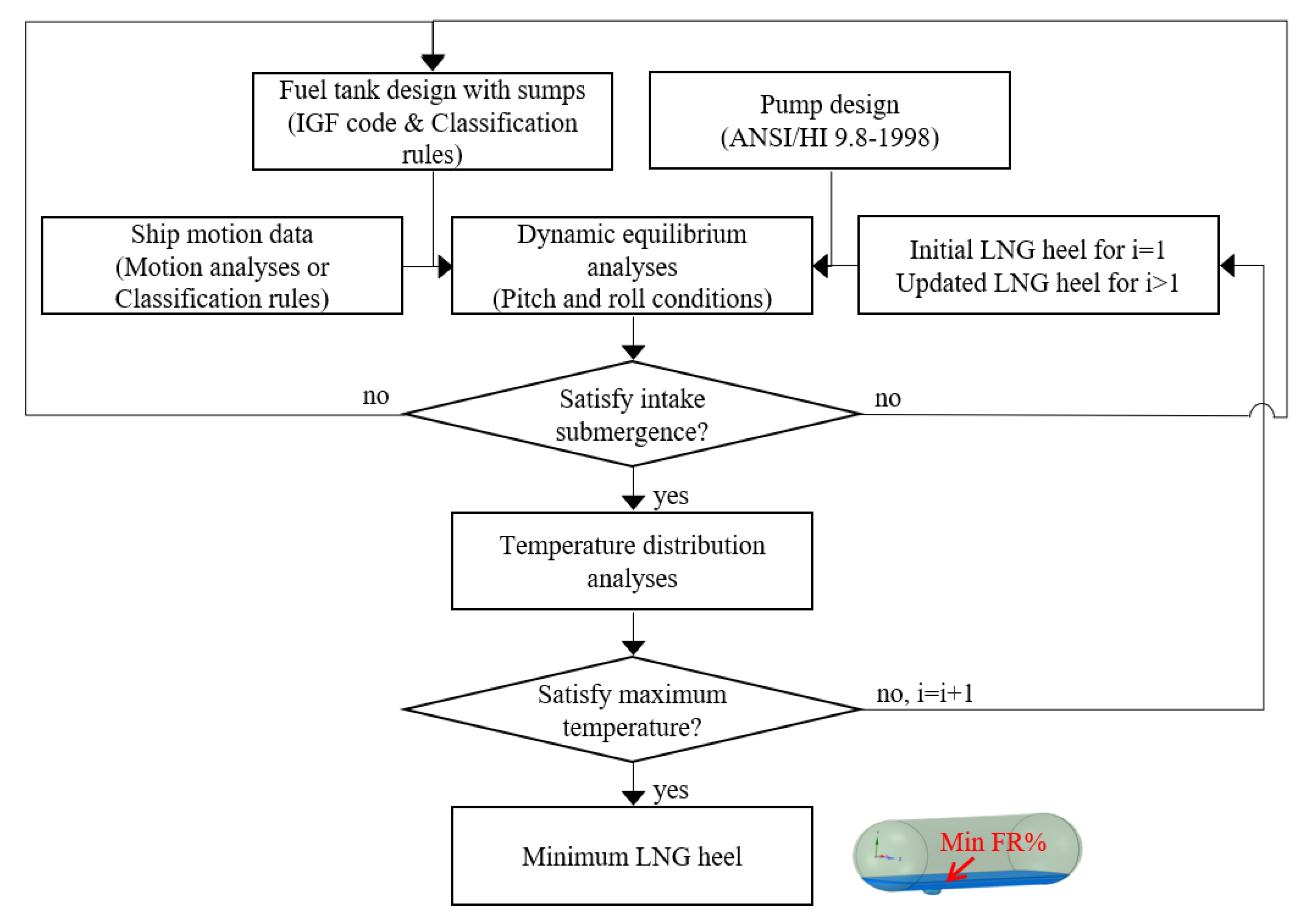
An LNG fuel tank should be designed based on the standard IGF code [
22], and specifications of the fuel pump follow the designed fuel pump. As depicted in
Figure 1, the LNG heel determination process should feed back to the LNG fuel tank design because it directly impacts the usable capacity of a tank. The required tank heel is determined by several factors, including the volume and shape of the tank, the ship’s operating conditions, engine gas consumption, heat transfer from external sources, and bunkering and voyage schedule.
An LNG heel is the minimum LNG volume to fuel. The minimum filling ratio can range from 2% to 33%, depending on the cases [
23,
24,
25]. With regard to the initial design considerations, the minimum filling ratio of 10% can be assumed as a rule of thumb. The amount of LNG remaining in the tank directly affects the tank’s pressure and temperature and the bunkering process [
26]. When the amount of LNG is insufficient to maintain the tank at a critical temperature, bunkering thermal shock can occur in the LNG fuel tank because of the significant temperature difference between the tank atmosphere and charged LNG [
27]. In LNG fuel tank design, the tank heel needs to be minimized so that it provides an extended voyage distance, guaranteeing a tolerable thermal shock.
One of the most important specifications of the LNG pump is to keep the pump fully submerged in the LNG fuel to avoid gasification during suction in the tank. Most LNG fuel tanks adopt a sump which improves fuel pump submergence under reduced LNG heel volume.
The fuel pump setting with the relative distance to the sump tank can be referenced in the handbook of pump intake design ANSI/HI 9.8-1998 [
28]. The depth for fuel pump submergence, which is the level of liquid required above the suction inlet to avoid the vortex flow around the inlet and prevent the air inflow, is calculated using Equation (1).
where
S (m) denotes the fuel pump submergence,
Dpump (m) is the pump diameter, and
Q (m
3/s) is the flow rate.
Simulation models can be developed with the reference filling height. There are two steps of simulations for the determination of the optimal LNG heel. As a first step, dynamic sloshing simulations under ship motions are needed to ensure pump submergence, which should be monitored at every moment of ship motion. This step can be simulated based on conventional computational fluid dynamics (CFD) or SPH. The next step is to check if the filling head satisfying the pump submergence can be acceptable in terms of LNG thermal differences. CFD and finite element analysis (FEA) are alternatively used for the second step. For more rigorous evaluation, LNG boil-off, which leads to a decrease in the volume of liquid, can be considered.
2.2. SPH Method
A number of publications related to the SPH method have been reported. In general, the SPH method is more reasonable than Lagrangian finite element analyses and even than coupled Eulerian–Lagrangian analyses when the deformation is remarkably developed. As long as a relatively reasonable number of nodes associated with smoothed particle hydrodynamics is involved in the analysis model, the SPH method is known to be cost effective.
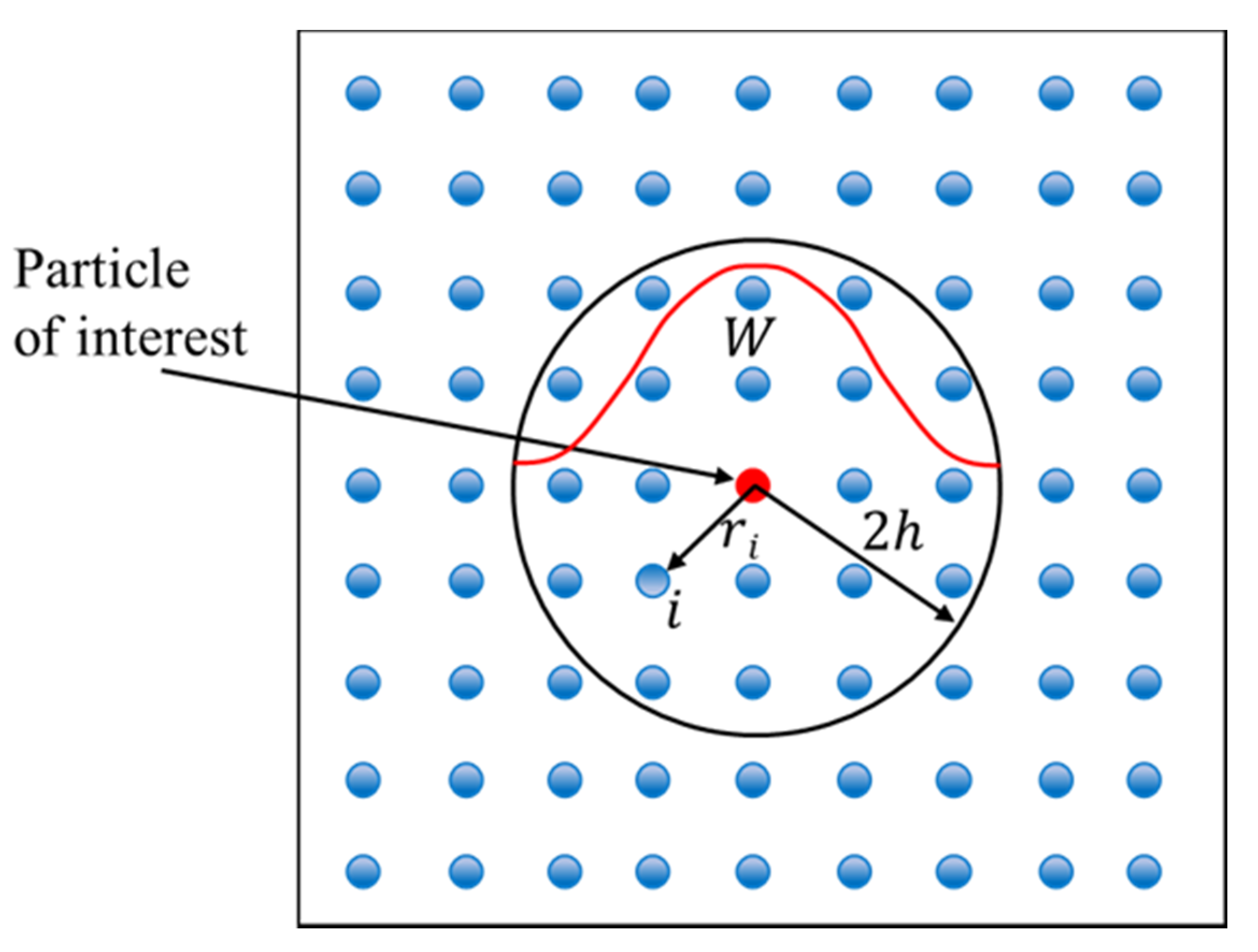
The SPH method is applied for dynamic sloshing simulations. For this method, nodes and elements are not generated as in conventional finite element analysis; instead, only a set of points and a uniform radius of the points are required to represent a fluid body. These spheres are known as particles or pseudo-particles in smoothed particle hydrodynamics.
The SPH method is based on interpolation theory to approximate a field variable at any point in a domain. The variable value at a particle of interest can be approximated by summing the contributions from a set of neighboring particles. The property
A of a particle was interpolated using a kernel function (
W), which is a function of the smoothing length,
h, and the distance with the neighboring
ith particle, as described in Equation (2) [
8]. A 2D example of the SPH model illustrates that a particle of interest is surrounded by
N particles, as shown in
Figure 2.
where
,
,
, and
denote the physical property, position, mass, and density of the
ith particle, respectively;
is the smoothing length;
is the position of the particle of interest; and
is the total number of particles within the smoothing length
.
3. LNG Heel Analyses
3.1. SPH Analysis Model
This paper refers to an LNG fuel tank mounted on a Wartsila WSD41 50K model, which is a 50,000 deadweight oil product tanker [
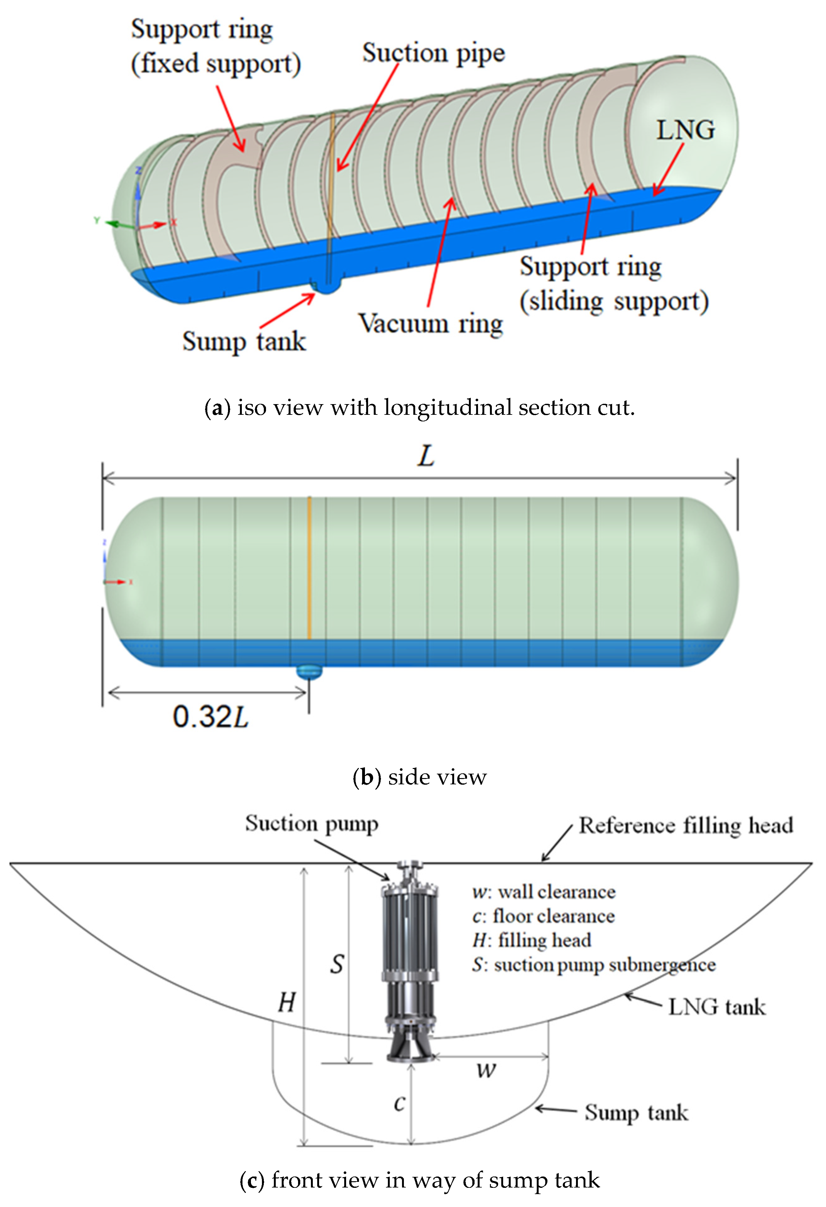
29], as a research object. The cargo ship has two LNG fuel tanks on board; both are identical in size. The sketches of the LNG fuel tank are shown in
Figure 3. The LNG fuel tank is supported by a fixed-support ring and sliding-support ring. The transverse vacuum rings are welded inside the tank to elevate the buckling strengths and to mitigate the LNG dynamic flows.
For tank heel minimization, the LNG fuel tank usually adopts a sump tank, which is located 0.322
L away from the rear end of the tank (see
Figure 3b). A suction pump is located to pump the LNG out. The design parameters of the sump tank such as the wall clearance (
W) and floor clearance (
c) are referenced in the handbook [
28].
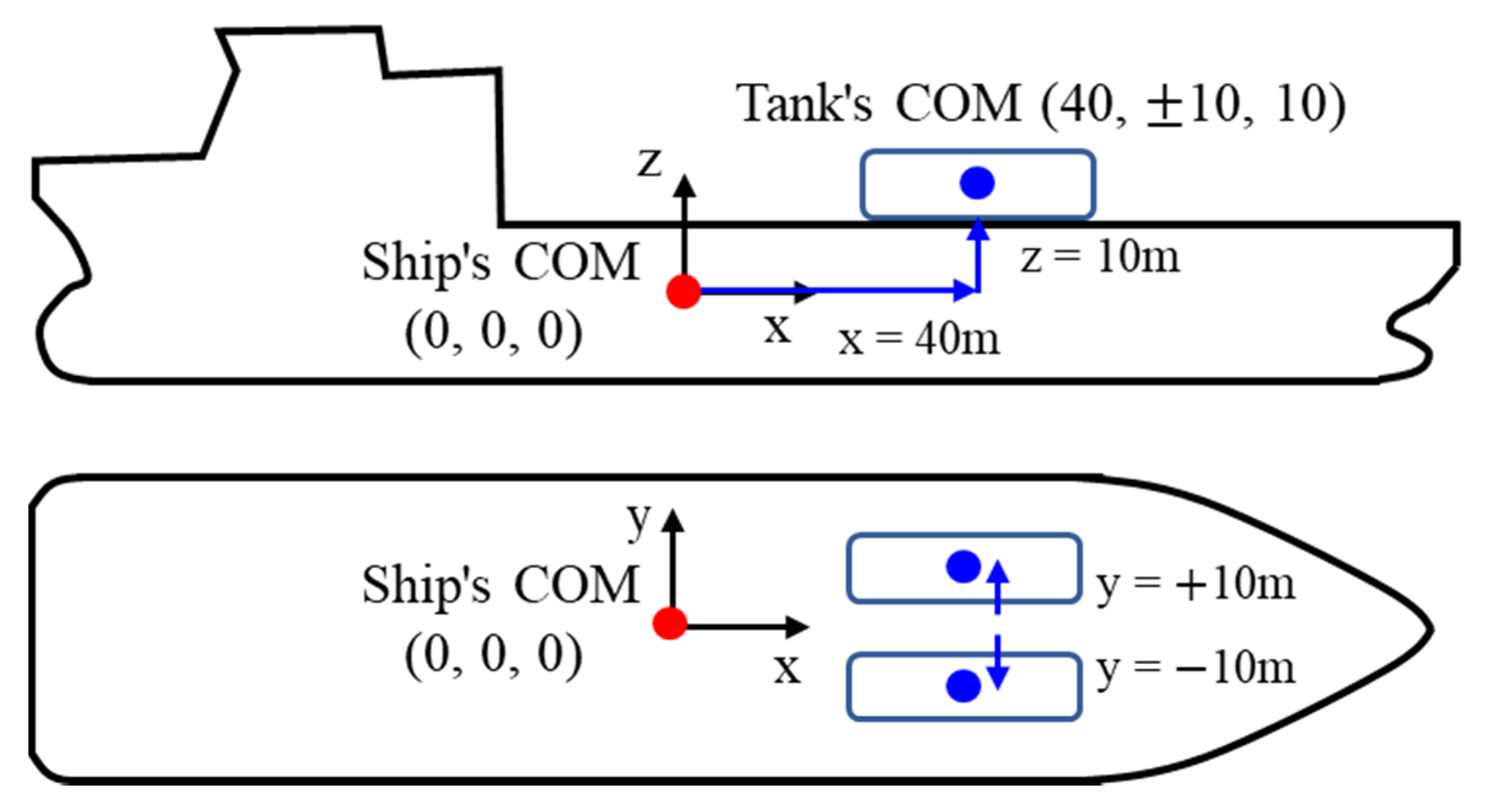
The position of an LNG fuel tank relative to the ship’s center of mass (COM) is presented in
Figure 4. In this study, only an analysis of the LNG fuel tank was performed. The motion of the tank in terms of pitch and roll refers to the COG of a ship. The analysis was performed for an LNG fuel tank on the port side.
A commercial finite element analysis (FEA) code, Abaqus/Explicit [
30], was used for all of the SPH analyses performed in this study. The SPH model of the LNG fuel tank included the tank structure and LNG. The tank was meshed as the rigid shell elements (R3D3 and R3D4), and the LNG was composed of the smoothed-particles, as shown in
Figure 5. The rigid shell element size was determined so that the shape of the round tank and internal reinforcement could be expressed reasonably.
The LNG fuel was modeled as smoothed-particle elements (PC3D). The size of the particle element needed to be small enough to represent the natural flow of the LNG. The size of the particle element was determined relative to the sump tank, which has the smallest tank dimension. Expecting that most localized flow can occur by way of the sump tank, the LNG particle size was determined so that enough particles could be contained in the sump tank. All particles were initially positioned offset by the distance of the particle size to prevent penetration of the particles through the tank wall. A probing beam element (B31) was inserted to measure if the suction pump was fully submerged in the fluid particles.
The LNG properties with density = 4.26 × 10⁻¹⁰ (ton/mm3) and viscosity μ = 1.46 × 10⁻¹⁰ MPa.s were assigned to the particle elements. To support the solution for the SPH model, the LNG was defined using the Hugoniot type linear equation of state with the parameters of the sound speed of 1.42 × 106 mm/s, the slope coefficient of 0, and the Grüneisen ratio equal to 0. The interaction between the LNG particles and the tank structure is defined through contact inclusions considering the particle radius.
3.2. Even Keel Condition
The SPH analyses for the even keel condition are necessary to check if the modeled particles maintain the intended filling head under the gravity load of 9810 mm/s
2. We assumed the Vanzetti pump [
31] as an LNG suction pump, which is located at the center of the sump tank. The net positive suction head available (NPSHa) was 940 mm, which corresponded to the filling ratio of 7.76%, as shown in
Figure 3c. Hereafter it is denoted as the reference filling ratio.
Based on the reference filling ratio, the SPH models with the increased filling ratios were generated to check the suction pump submergence even under the dynamic ship motion conditions. The SPH models are summarized in
Table 1, where the filling ratios ranged from 7.76% to 17%. A probing bar was cantilevered at the center of the sump tank bottom. Its free end of Model 1 was aligned with the filling head height, as delineated in
Figure 5.
A simulation time of 3 s was applied to each model to see the stabilized filling head under the even keel condition. There were some repeated attempts to add or subtract more particles until the filling head was aligned to the target head.
Figure 6 shows the converged results where the stabilized filling head of each LNG fuel tank model coincided with the top end of the probing bar. In addition, the number of particles corresponding to
Figure 6 was expressed in
Table 1. These SPH models are to be used for the roll and pitch dynamic conditions.
3.3. Dynamic Rolling and Pitching Conditions
After the even keel analysis was finished, the analyses were performed under the roll and pitch conditions. Some equations to determine the roll and pitch motions were taken from DNV ship rules [
1], as shown in Equations (3)–(6), where the values of
and
were assumed to be approximately 175 m and 32 m, respectively. The determined roll and pitch angles and periods were suggested in
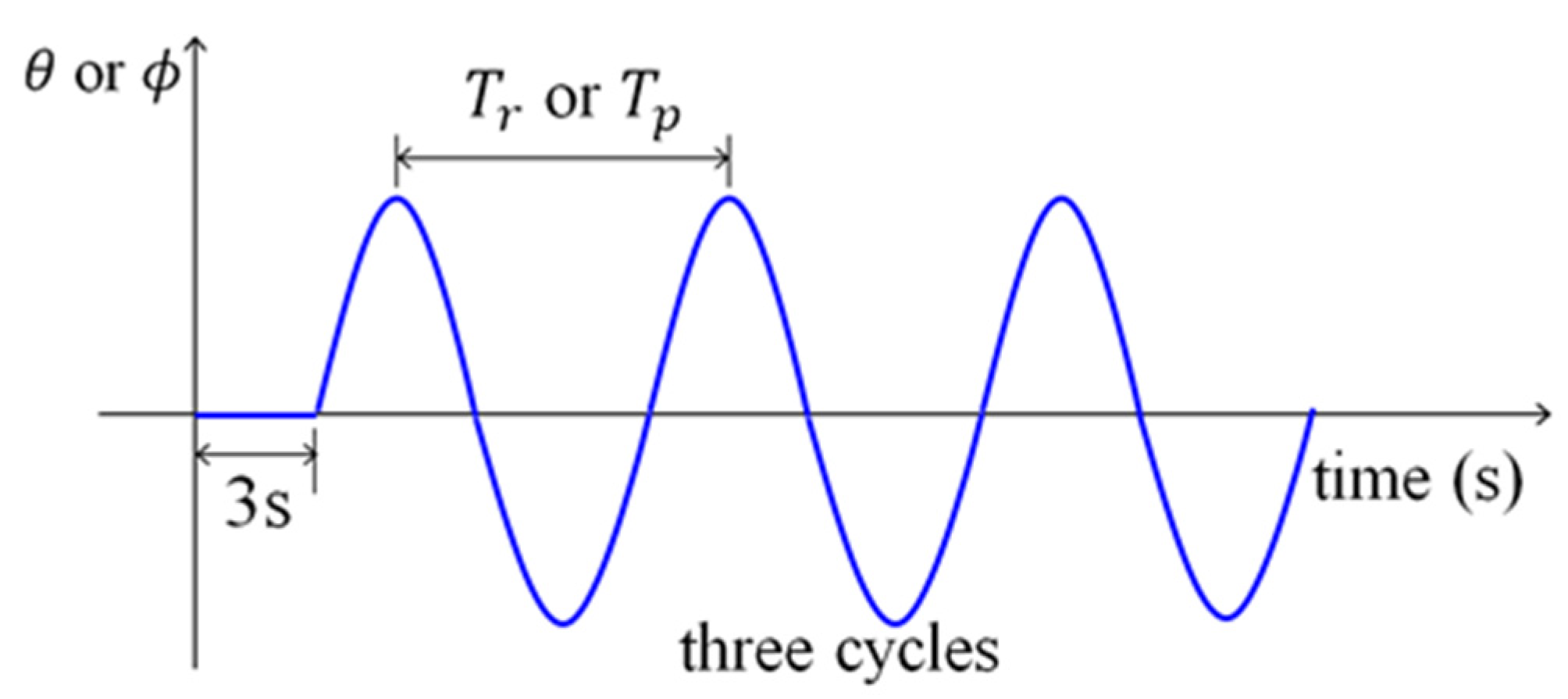
Table 2. Because roll or pitch motion in the first cycle should start in a stand-still state, three cycles of motion were repeated to confirm the more natural flow of LNG (refer to
Figure 7).
The gravitational force was applied for three seconds, and then the prescribed roll or pitch motion was applied each model. Since the roll or pitch motion starts just after being sufficiently stabilized by the gravity for 3 s, the flow response in the last cycle is regarded as being most realistic.
During the roll cycles, the submergence of the probing bar was visually inspected every 0.1 s.
Figure 8 shows five photos per cycle in Model 3. They include the captured snaps at the cycle beginning, peak, zero-crossing, and valley points in each cycle. The patterns of free surfaces at an observation moment look similar to each other for second and third cycles, while the free surface pattern for the first cycle is different from those for the second and third cycles. This means that the fluid flow was stabilized from the second cycle.
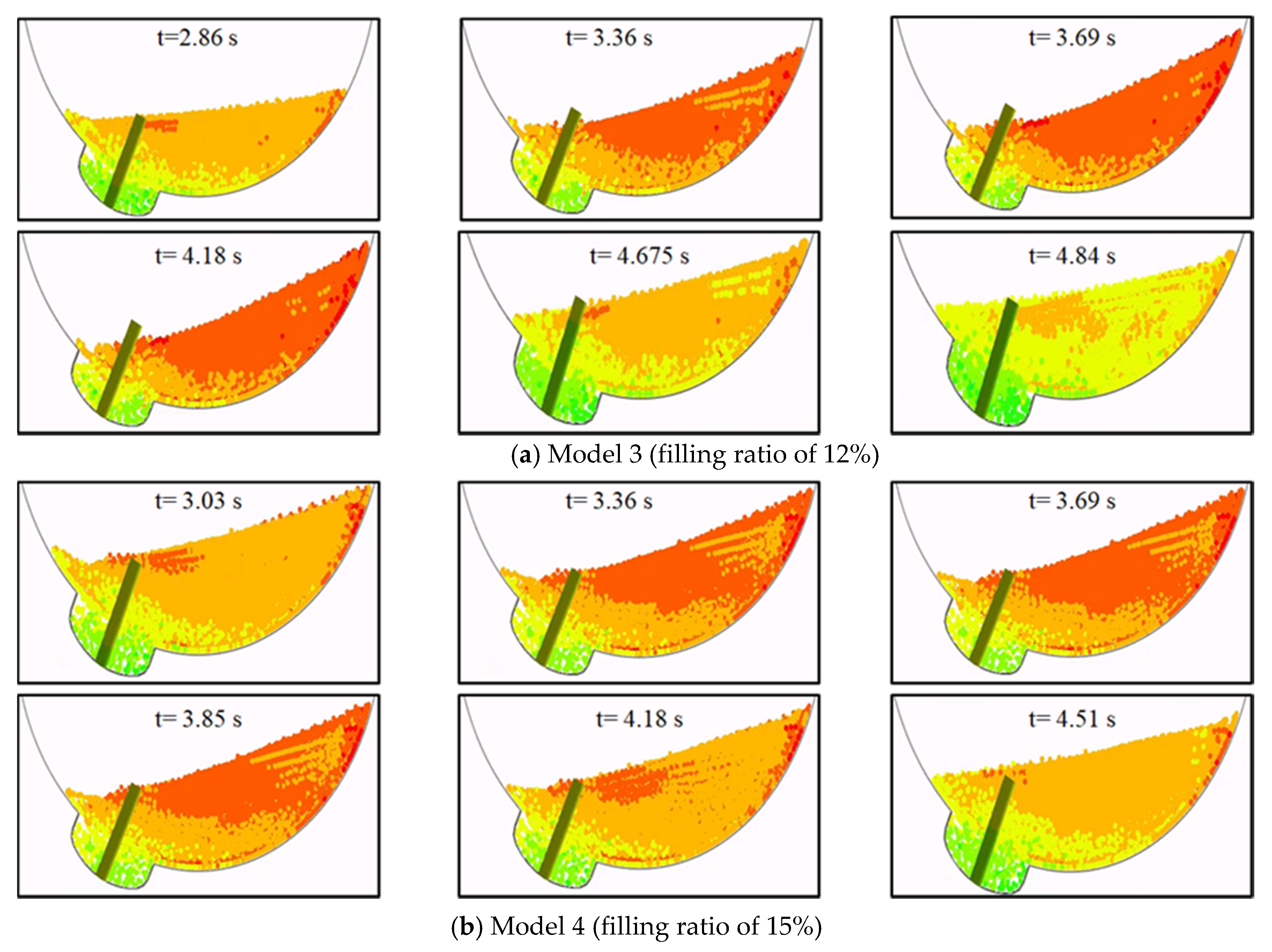
We observed the flow pattern in the third cycle at which the flow was stabilized more closely and present it in
Figure 9. It can be seen from
Figure 9a that when the filling ratio is 12%, the probing bar is exposed to the air at several moments. On the other hand, when the filling ratio is increased to 15%, the probing bar is almost immersed in the fluid particles (see
Figure 9b). Therefore, under rolling conditions, 15% can be determined as the minimum filling ratio.
With the filling ratio of 15%, it can be seen in
Figure 10 that the probing bar was stably submerged under the pitching motion. Through a comparison of
Figure 9 and
Figure 10, it can be seen that the suction pump was submerged more stably in the pitch condition than in the rolling condition. It is considered that the vacuum rings inside the LNG fuel tank suppressed the longitudinal flow.
4. Conclusions
The process of minimizing the LNG tank heel considering ship motions and thermal distributions was presented in a flow chart, and this paper considered only the vessel motion effects. The first condition for determining the minimum tank heel was that the suction pump was submerged during the flow of LNG due to the motion of the hull. The second condition was that the determined tank heel did not induce thermal shock due to LNG reloading. This paper introduced the process of determining the minimum tank heel that satisfies the first condition. The SPH method was used to implement the LNG heel numerical analyses, and the theoretical background of the SPH method was introduced. The LNG fuel tank was dimensioned to be mounted on the fore deck of a 50,000-deadweight product tanker.
The filling head whose suction pump top coincided with the free surface was determined as the reference LNG heel. The corresponding reference filling ratio was 7.76%. Four cases (10%, 12%, 15%, and 17%) with an increase over the reference filling ratio were considered.
To check whether the initially determined fluid particles satisfy the target filling head corresponding to each case, the fluid particles were repeatedly added or subtracted for even keel conditions. To confirm the suction pump submergence in the dynamic condition, the amplitudes and periods of the roll and pitch motions of the hull were calculated based on the classification rules. Due to the characteristics of the LNG fuel tank arranged in the longitudinal direction of the hull, the roll motion was more critical than the pitch motion. The 15% filling ratio was determined as the minimum tank heel due to roll motion, and stable suction pump submergence was confirmed even in pitch motion.
As a future study, the minimum tank heel determined in this study can be confirmed only when thermal shock is determined through heat transfer analysis considering the vaporization of LNG. To minimize the tank heel, it is very important not only to optimize the shape of the sump tank, but also to select the position of the LNG tank relative to the COM of the ship. Future study on this is necessary.
Author Contributions
Conceptualization, K.-S.P.; methodology, J.C.; software, H.-T.L.; validation, J.C. and K.-S.P.; formal analysis, H.-T.L.; investigation, K.-S.P. and J.C.; resources, K.-S.P.; data curation, J.C.; writing—original draft preparation, H.-T.L. and J.C.; writing—review and editing, J.C.; visualization, H.-T.L.; supervision, J.C.; project administration, J.C.; funding acquisition, K.-S.P. All authors have read and agreed to the published version of the manuscript.
Funding
This research was funded by POSCO. The APC was funded by Inha University.
Institutional Review Board Statement
Not applicable.
Informed Consent Statement
Not applicable.
Data Availability Statement
The data presented in this study are available on request from the corresponding author. The data are not publicly available due to funding requirements.
Acknowledgments
The present work was carried out with the support of an Inha Research Grant and POSCO. Their support is highly acknowledged.
Conflicts of Interest
The authors declare no conflict of interest.
Nomenclature
| Latin symbols |
| |
| Sum of particles properties’ around the particle of interest within the smooth length
h |
| Molded breadth of a ship in meters |
| Depth of LNG fuel tank |
| Pump diameter |
| Young’s modulus |
| Gravitational constant |
| Smooth length |
| Filling head |
| Length of LNG fuel tank |
| Length between perpendicular of a ship in meters |
| |
| |
| Flow rate |
| Position of the particle of interest |
| |
| Suction pump submergence |
| Pitch period |
| Roll period |
| Kernel function |
| Greek symbols |
| Density of LNG |
| |
| Viscosity of LNG |
| Pitch angle in degree |
| Roll angle in degree |
References
- DNV Rules and Standards. Available online: https://www.dnv.com/rules-standards%20 (accessed on 1 April 2021).
- Li, K.; Wang, G.; Liu, C. Study on Calculation of Liquid Level AND Storage of Tanks for LNG-Fueled Vessels. In Proceedings of the International Conference on Advanced Environmental Engineering (ICAEE2017), Shenzhen, China, 15–17 December 2017; p. 111. [Google Scholar]
- Kim, T.W.; Kim, S.K.; Park, S.B.; Lee, J.M. Design of Independent Type-B LNG Fuel Tank: Comparative Study between Finite Element Analysis and International Guidance. Adv. Mater. Sci. Eng. 2018. [Google Scholar] [CrossRef] [Green Version]
- Ding, S.; Wang, G.; Luo, Q. Study on Sloshing Simulation in the Independent Tank for an Icebreaking LNG Carrier. Int. J. Nav. Archit. Ocean Eng. 2020, 12, 667–679. [Google Scholar] [CrossRef]
- Nasar, T.; Sannasiraj, S.; Sundar, V. Experimental Study of Liquid Sloshing Dynamics in a Barge Carrying Tank. Fluid. Dyn. Res. 2008, 40, 427–458. [Google Scholar] [CrossRef]
- Ashkan, R.; Fabrizio, P.; Krish, T. Study of Liquid Sloshing: Numerical and Experimental Approach. Comput. Mech. 2011, 47, 65–75. [Google Scholar]
- Rafiee, A.; Thiagarajan, K.P. An SPH Projection Method for Simulating Fluid–Hypoelastic Structure Interaction. Comput. Meththods. Appl. Mech. Eng. 2009, 198, 2785–2795. [Google Scholar] [CrossRef]
- Monaghan, J.J. Smoothed particle hydrodynamics. Annu. Rev. Astron. Astrophys 1992, 30, 543–574. [Google Scholar] [CrossRef]
- Ryu, M.C.; Jung, H.J.; Kim, Y.S.; Kim, Y. Sloshing Design Load Prediction of a Membrane Type LNG Cargo Containment System with Two-Row Tank Arrangement in Offshore Applications. Int. J. Nav. Archit. Ocean Eng. 2016, 8, 537–553. [Google Scholar] [CrossRef] [Green Version]
- Rudman, M.; Cleary, P.W.; Prakash, M. Simulation of Liquid Sloshing in Model LNG Tank Using Smoothed Particle Hydrodynamics. Int. J. Offshore. Polar. Eng. 2009, 19, 286–294. [Google Scholar]
- Hu, Z.Q.; Wang, S.Y.; Chen, G.; Chai, S.H.; Jin, Y.T. The Effects of LNG-Tank Sloshing on the Global Motions of FLNG System. Int. J. Nav. Archit. Ocean Eng. 2017, 9, 114–125. [Google Scholar] [CrossRef] [Green Version]
- Gomez-Gesteira, M.; Rogers, B.D.; Dalrymple, R.A.; Crespo, A.J.C. State-of-the-Art of Classical SPH for Free-Surface Flows. J. Hydraul. Res. 2010, 48, 6–27. [Google Scholar] [CrossRef]
- Green, M.D.; Peiró, J. Long Duration SPH Simulations of Sloshing in Tanks with a Low Fill Ratio and High Stretching. Comput. Fluids 2018, 174, 179–199. [Google Scholar] [CrossRef]
- Lee, H.; Choi, J.H.; Jung, I.C.; Lee, S.G.; Yoon, S.D.; Ryu, B.R.; Kang, H.K. Effect of Parameters on Vapor Generation in Ship-to-Ship Liquefied Natural Gas Bunkering. Appl. Sci. 2020, 10, 6861. [Google Scholar] [CrossRef]
- Oh, S.H.; Jung, D.W.; Kim, Y.H.; Kwak, H.U.; Jung, J.H.; Jung, S.J.; Park, B.W.; Cho, S.K.; Jung, D.H.; Sung, H.G. Numerical Study on Characteristics and Control of Heading Angle of Floating LNG Bunkering Terminal for Improvement of Loading and Off-Loading Performance. J. Ocean. Eng. Technol. 2020, 34, 77–88. [Google Scholar] [CrossRef]
- Yan, G.; Gu, Y. Effect of Parameters on Performance of LNG-FPSO Offloading Systemin Offshore Associated Gas Fields. Appl. Energy 2010, 87, 3393–3400. [Google Scholar] [CrossRef]
- Chung, S.M.; Seo, Y.S.; Jeon, G.M.; Kim, J.W.; Park, J.C. Parameter Study of Boiling Model for CFD Simulation of Multiphase-Thermal Flow in a Pipe. J. Ocean Eng. Technol. 2021, 35, 50–58. [Google Scholar] [CrossRef]
- Shao, Y.; Lee, Y.H.; Kang, H.K. Dynamic Optimization of Boil-Off Gas Generation for Different Time Limits in Liquid Natural Gas Bunkering. Energies 2019, 12, 1130. [Google Scholar] [CrossRef] [Green Version]
- Effendy, S.; Khan, M.S.; Farooq, S.; Karimi, I.A. Dynamic Modelling and Optimization of an LNG Storage Tank in a Regasification Terminal with Semi-Analytical Solutions for N2-Free LNG. Comput. Chem. Eng. 2017, 99, 40–50. [Google Scholar] [CrossRef]
- Srikanth, A.; Narasimhan, S.; Narasimhan, S. Optimization of Unloading Operations in Petroleum Product Storage Terminals. Ind. Eng. Chem. Res. 2014, 53, 13728–13735. [Google Scholar] [CrossRef]
- Kim, J.W.; Jeong, J.Y.; Chang, D.J. Optimal Shape and Boil-Off Gas Generation of Fuel Tank. J. Ocean Eng. Technol. 2020, 34, 19–25. [Google Scholar] [CrossRef]
- Maritime Safety Committee. International Code of Safety for Ships Using Gases or Other Low-Flashpoint Fuels (IGF Code); International Maritime Organization (IMO): London, UK, 2016. [Google Scholar]
- Hernes, H.E. Active and Passive Measures to Maintain Pressure in LNG Fuel Systems for Ships. Master’s Thesis, Norwegian University of Science and Technology, Tronheim, Norway, 2015. [Google Scholar]
- Dobrota, D.; Lalic, B.; Komar, I. Problem of Boil—off in LNG Supply Chain. Trans. Marit. Sci. 2013, 2, 91–100. [Google Scholar] [CrossRef] [Green Version]
- Styliadis, T.; Koliousis, I. Lng Operations: Safety Issues and Procedures. 2015. Available online: https://www.onthemosway.eu/wp-content/uploads/2015/06/lng-operations.pdf (accessed on 30 May 2021).
- Shao, Y.; Lee, Y.H.; Kang, H.K. Parametric Investigation of BOG Generation for Ship-to-Ship LNG Bunkering. J. Korean Soc. Mar. Environ. Saf. 2018, 24, 352–359. [Google Scholar] [CrossRef]
- Jason, P.P.; Carlos, L.; Victor, F.; Robert, J.K.; Gerald, W.; James, D.; Daniel, V.; Mike, H. Lng Vessel Cascading Damage Structural and Thermal Analyses; Sandia National Laboratories: Albuquerque, NM, USA, 2013. [Google Scholar]
- American National Standard for Pump Intake Design. ANSI/HI 9.9-1998. Available online: http://marineman.ir/wp-content/uploads/2015/03/ANSI-HI_9.8.pdf (accessed on 30 May 2021).
- Wartsila WSD41 50K, 50,000 DWT Oil Product Tanker. Available online: https://www.wartsila.com/wsd41-50k (accessed on 1 April 2021).
- Simulia Abaqus User Manual. Available online: https://abaqus-docs.mit.edu/2017/English/SIMACAEEXCRefMap/simaexc-c-docproc.htm (accessed on 1 April 2021).
- Vanzetti Pump. Available online: https://www.vanzettiengineering.com/en (accessed on 1 April 2021).
| Publisher’s Note: MDPI stays neutral with regard to jurisdictional claims in published maps and institutional affiliations. |
© 2021 by the authors. Licensee MDPI, Basel, Switzerland. This article is an open access article distributed under the terms and conditions of the Creative Commons Attribution (CC BY) license (https://creativecommons.org/licenses/by/4.0/).


