1. Introduction
Unmanned aerial vehicle (UAV) related applications most frequently apply optical sensors, which provide visibility from above. Unfortunately, the abilities of such sensors are limited by atmospheric conditions and illumination. Radar sensors can be used at night and in poor visibility conditions. Radars on manned aircraft are considered conventional means for various purposes, such as surveillance of weather, ground, or other aircraft [
1,
2]. The same features became a standard on UAVs [
3,
4,
5], especially for specific tasks, such as ground penetration [
6].
Due to high costs and heavy weight, radars are not widely used with UAVs. There are solutions based on fixed-wing UAV platforms carrying the radars, such as the IAI Searcher or the IAI Heron, however, both of those platforms are extremely large (up to 1.2 t in case of the IAI Heron), have an extremely high price, and are used solely in military operations. The millimetre-wave radar provides an alternative solution to overcome the shortcomings of optical solutions because data in the microwave range can be acquired independently of atmospheric conditions and time of day [
7,
8].
The latest developments of mmWave technologies provide good potential for applications using UAVs due to decreased costs and weight. Usage of mmWaves allows reduction of the size of the antenna to get good range and angular resolution, but the range is limited by the order of hundreds of meters. Cheap low-power C or K-band radars can only be used as terrain estimation and altitude sensors [
9,
10,
11,
12,
13]. A similar application of low power higher frequency W-band radars usually achieves slightly more detailed results [
14,
15]. Another small range task for which radars are very suitable is collision avoidance and all mentioned band radars were tested for this purpose [
16,
17].
For radar applications in marine traffic or ice monitoring, the range of the order of kilometres or tens of kilometres is needed. Marine radars fulfil this requirement [
17,
18].
A concept for a scalable radio frequency (RF) sensor payload for small UAVs that can perform multiple RF functions such as a synthetic aperture radar (SAR), ground moving target indication (GMTI), and electronic support measures (ESM) was analysed and presented in [
19]. The digitization of the antenna signals on transmission and reception at the antenna element level was essential to the scalable multi-function RF payload concept. The architecture of a technology demonstrator based on an X-band SAR that can perform radar and ESM functions was introduced and usage of the X-band radar on the small UAV was justified.
In recent times, the technologies of marine radars have been rapidly growing and becoming more and more advanced. The marine radar market is big enough to provide low-cost radars for customers. The development of technologies of semiconductors such as high power transistors, integrated circuits, field-programmable gate arrays (FPGA) allows for improved radar parameters such as range, power consumption, weight, as well as decreasing the cost of radar equipment. At this time, solid-state FMCW and pulse compression radars are permanently replacing magnetron pulse radars. For our experiments, we have chosen the Simrad 4G™ FMCW marine radar, which we adapted to provide a possibility to integrate it on the UAV.
2. Concept of the Experiment
Using a UAV to elevate the marine radar to high altitudes provides a wider field of view and consequently a longer detection range. However, higher altitudes could lead to higher radio interference levels. Practical estimation of radio interferences affecting the solid-state FMCW marine radar at altitudes up to 120 m was the main objective of our experiment. An RTL SDR AIS (automatic identification system) receiver based on software-defined radio was arranged on our UAV for the implementation of the concept of both primary (marine radar) and secondary (AIS) radars on the UAV. Usage of both technologies can provide additional possibilities for marine traffic, anti-piracy, and border protection control.
The Simrad 4G™ FMCW marine radar was chosen due to its low weight, domed antenna, low power consumption, readiness, safety of usage, possibility to use open software, and good ability to detect RCS targets both at low altitudes and at short ranges. The last property may be useful for applications such as detection of other UAVs. Experiments on detection of small UAVs using this radar from the ground are presented in [
20].
It is important to mention that, according to the directivity diagram data of the Simrad 4G™ FMCW marine radar‘s antenna, which is presented in the radar‘s brochure, the sidelobe level of the radar‘s Tx and Rx antenna is below –18 dB when within ±10° and below –24 dB outside ±10°, the vertical beamwidth (–3 dB) is 25° ± 20% and the horizontal beamwidth (–3 dB) is 5.2° ± 10% [
21].
3. Experimental Setup
The weight of the radar is 7.4 kg. Taking into account the weight of additional equipment such as a separate power supply, minicomputer, communication equipment, and the AIS receiver, the UAV must be capable to lift a payload weight at least 10 kg. For this experiment, only lifting the radar to high altitudes is required. The altitude is limited to 120 m due to regulations. A rotary-wing UAV is the optimal choice for this task. Since the payload of approximately 10 kg was foreseen, the multi-rotor UAV was specially designed for this task. The maximum takeoff weight (MTOW) of this vehicle is 25 kg (though potentially it could lift off with greater load). The MTOW of 25 kg was chosen to ensure easier certification and flight clearances (in most of the countries 25 kg is the maximum mass for small UAVs).
To ensure convenient mounting of the radar and possibilities of modification, the multi-rotor was fully custom built having the size of the radar, its mounting points, endurance, needed electronic systems, transportation possibilities, possible modifications and etc. in mind.
To increase the safety in case of failure of one of the engine systems (since it is supposed to carry quite expensive equipment) the 8 motor layout (octocopter) was chosen. It must be mentioned that the increase of number of motors and especially the number of propellers decreases the overall efficiency of the vehicle both due to lower efficiency of multiple electric motors (though not so obvious) and due to increase of induction drag and tip losses on the multiple propellers. It is always more preferable from an efficiency point of view to have as few propellers and motors as possible (and propellers with as little RPM as possible), nonetheless from the safety point of view, increase of the number of motors provides additional safety to the flight in case of failure. In the case of the octocopter’s configuration, the failure of a single motor does not lead to a crash and the vehicle in most of cases can safely return to the takeoff point. Even a failure of several motors in most of the cases leads to safe landing of the vehicle.
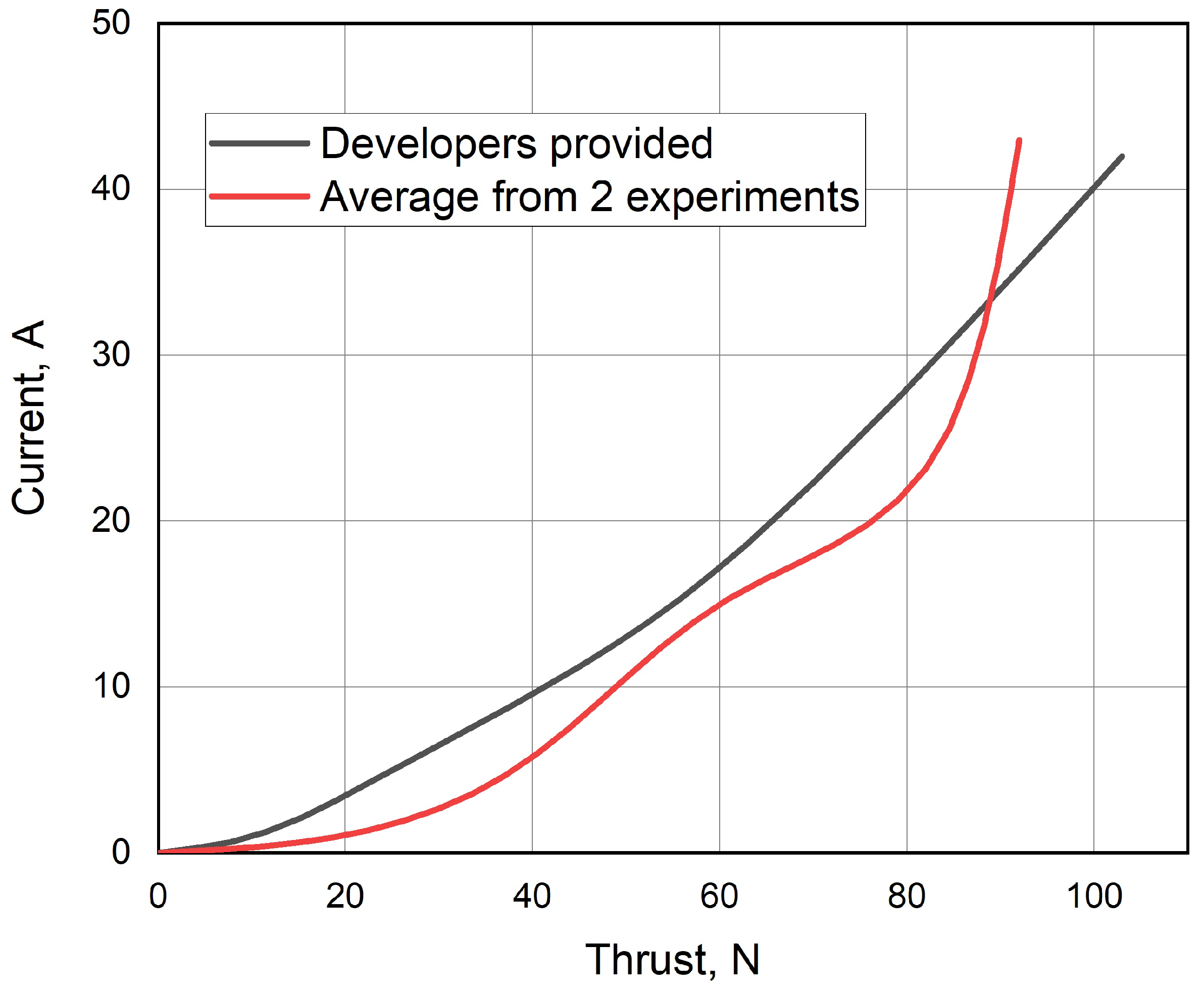
According to preliminary calculations, a combination of Turnigy Multistar 9235 100 KV brushless motors and Multistar carbon fiber 32 × 5.5 propellers was chosen. These 2.8 kW maximum power motors are designed to work using a 30–48 V supply (8-12S Li-Po battery) with a maximum current of 57 A, the weight of the motor is 674 g [
22]. Mentioned motors, while having a quite low rotation speed (100 RPM/V), provide comparatively high propeller efficiency. The experimental engine/propeller thrust data from the chosen 48 V supply are given in
Figure 1.
As it can be seen from
Figure 1, each motor/propeller provides around 100 N (9.81 kg) of static thrust, which is excessive for a 25 kg multi-rotor UAV (normally 400–500 N of total thrust would be sufficient). Nonetheless, this octocopter configuration (8 motors) was chosen in order to increase safety and versatility of the vehicle.
Since the multi-rotor was designed by implementing non-aviation grade composite materials, additional experimental laboratory static strength testing was performed. According to the mentioned testing, the maximum static strength of manufactured carbon fiber materials was in range of 255 MPa. In accordance to that data, modeling of full strength properties was performed and presented in
Figure 2. According to the modeling data, the frame strength is far in excess of planned maximum loads.
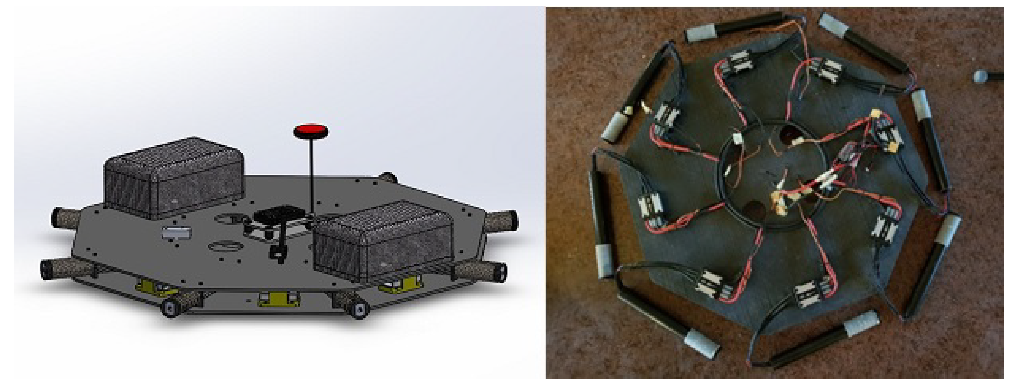
To ensure convenient transportation (and some possible modifications) the multi-rotor motor arms were manufactured in a detachable manner, i.e., the arms together with the motors and propellers could be detached from the central part, which houses all of the systems of the vehicle. That ensured convenient transportation of the vehicle and simple and quick replacement of the motor arms, which were the most vulnerable parts of the vehicle (
Figure 3).
To control the UAV, open source hardware and software Pixhawk 2 (Cube) with Ardupilot onboard were used. The implementation of open source equipment allows for quite simple integration of the needed features into the UAV system (like the determination of a direction for the radar operations and etc.). To ensure the autopilot telemetry data link, a 868 MHz frequency system was used, which does not interfere with the radar’s operations. In parallel to that, a 2.4 GHz manual multi-copter control system was implemented, which was mostly used for takeoff, landing or tuning of the vehicle’s systems.
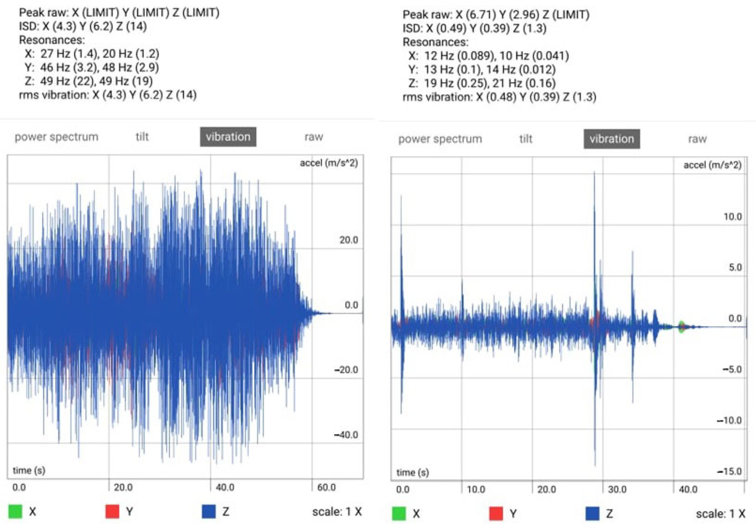
One of the serious problems during initial testing was the amount of vibrations on the multi-rotor control system (Pixhawk autopilot). The vibrations caused some very serious control problems, especially in altitude control of the vehicle. Since the used Pixhawk autopilot is an opensource design (both hardware and software) no precise requirements for the vibration level are available. The acceptable or non-acceptable vibration levels are determined purely by the influence on autopilot control characteristics (which is an additional problem). To determine the vibrations practical tests were performed with vibration level measurements on the multi-rotor while in flight. As was predicted, the highest level of vibrations was determined on Z (vertical) axis having the peaks at 49 Hz of 22 m/s, and an RMS for the Z axis of 14 m/s.
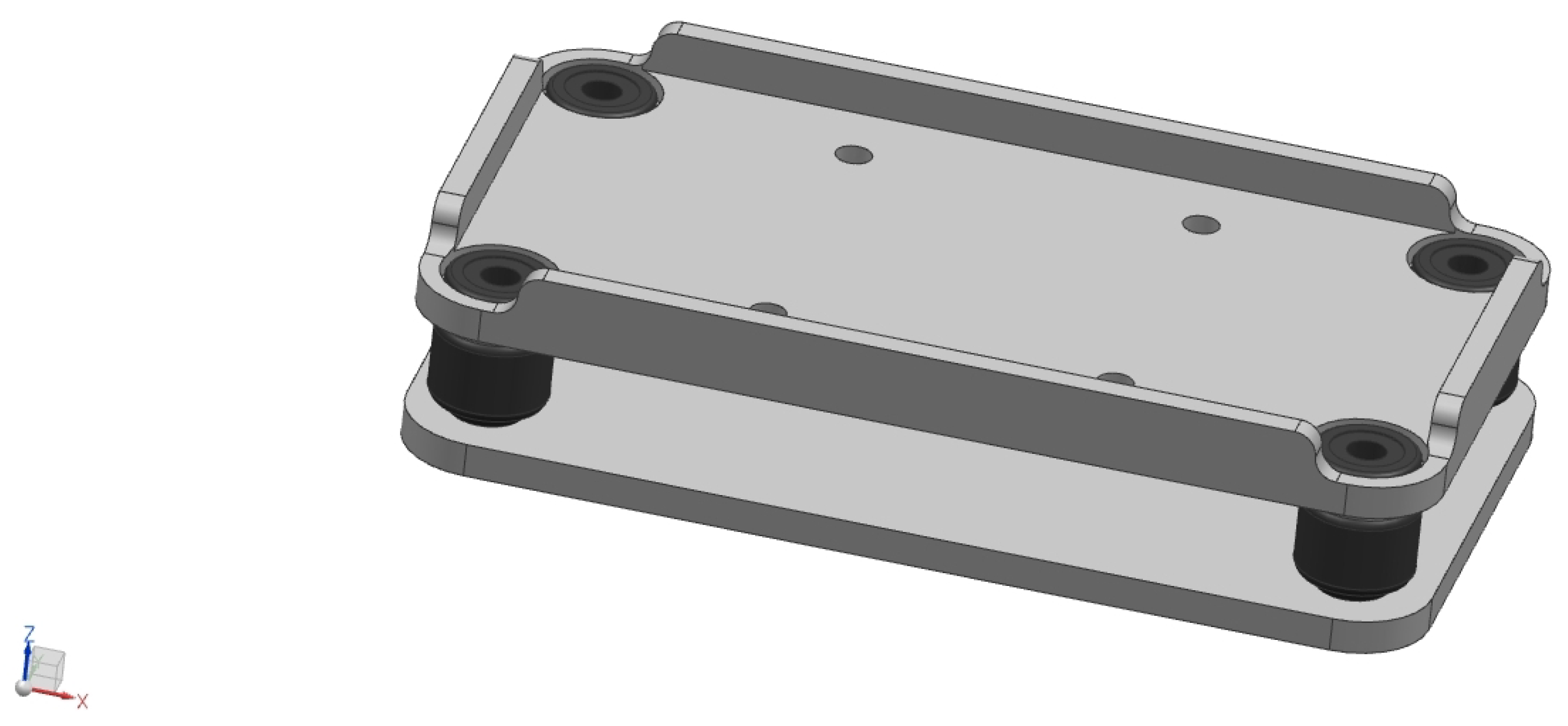
At such level of vibrations, the Pixhawk autopilot was not capable of providing a sufficient level of control of the vehicle (altitude control was affected especially). To deal with the problem a specially damped mounting plate for the autopilot was designed (
Figure 6), consisting of specially designed plates and standard vibration damping mounts (used for camera suspension).
The vibration mounts used are silicon-based “ball dampers”, which are frequently used for camera stabilization. Unfortunately, precise damping parameters were not initially known, therefore the dampers were experimentally selected from the number of available ones by careful matching of the dampers and the additional damping weights. Implementing the mentioned equipment the vibration level was considerably decreased (
Figure 7).
As can be seen from
Figure 7, the vibration level was decreased approximately 10 times, from an RMS of 14 m/s
for
Z axis without dampening to 1.3 m/s
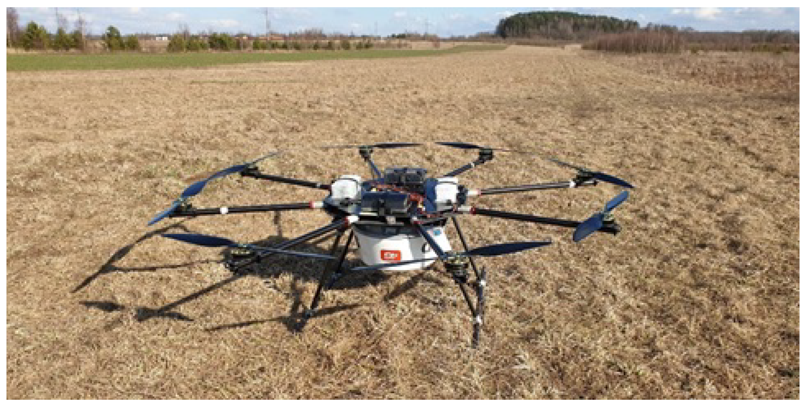
with damping. That decrease of the vibration level was quite sufficient to ensure stable and reliable both manual and fully automatic control of the vehicle shown in
Figure 5. It should be noted again that no precise requirements concerning acceptable vibration level are available for Pixhawk equipment, only abstract recommendations and the need for experimentally based results.
Since the UAV/radar conjunction was intended to be a proof of concept solution, the vehicle had a limited endurance of around 25 min and was mostly used in hovering flight mode (just to raise the radar to a certain altitude). In the mentioned hovering mode the multi-rotor was mainly controlled by the autopilot (in fully automated mode) with altitude and position data being transferred in real-time to the radar control hardware.
The multi-rotor shown in
Figure 5 was powered by a set of standard 6s (24 V) Li-Po batteries with several DC-DC voltage converters (step down conversion to 5 V) and Engine Speed Controllers (ESCs) for brushless (BLDC or AC synchronous) motors, of which the interference with radar operations are further described.
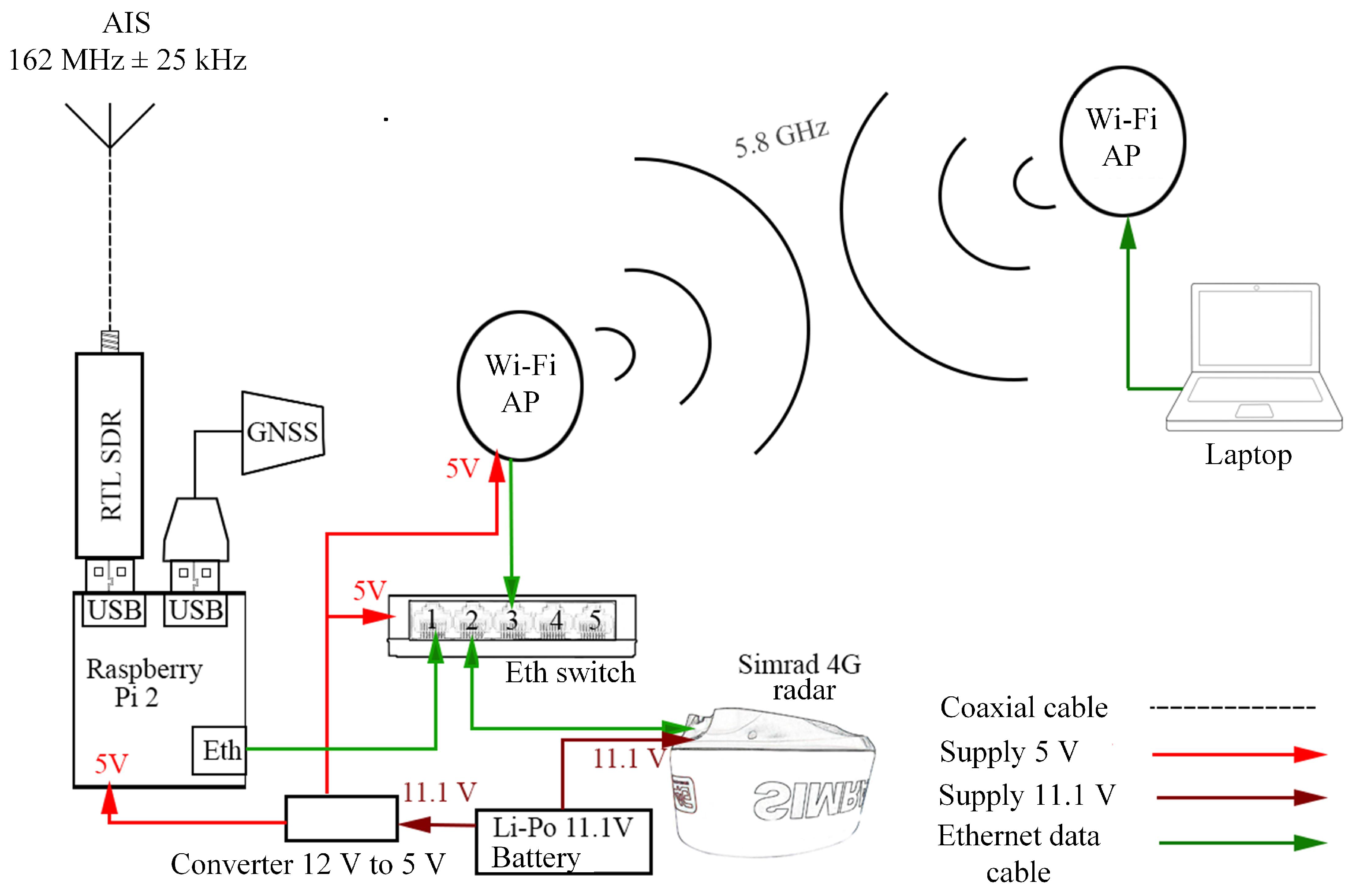
The payload was implemented as stand-alone equipment with its power supply (Li-Po battery), GNSS receiver dongle, and communication systems as presented in
Figure 8. It provides simple integration of the payload into the UAV to test the proof of concept. Usually, the Simrad 4G™ radar is connected to the chart plotter via interface RI-11. Both would add unnecessary weight if used. We were able to bypass the usage of those components by using open source code software OpenCPN to control the radar and display radar measurement data. The whole radar system was arranged at the bottom of the UAV in a bottom-up position to achieve greater stability of the UAV. The Simrad 4G™ radar was powered directly from an 11.1 V Li-Po battery. The radar data was sent via Ethernet cable connected to a Wi-Fi station module with a simple network switch in between. Radar, AIS, and GNSS position data were collected by the Raspberry Pi 2 computer and transferred together with the radar data stream in real-time via an ordinary 5.8 GHz Wi-Fi communication link to the computer on the ground.
4. Results of the Primary Radar
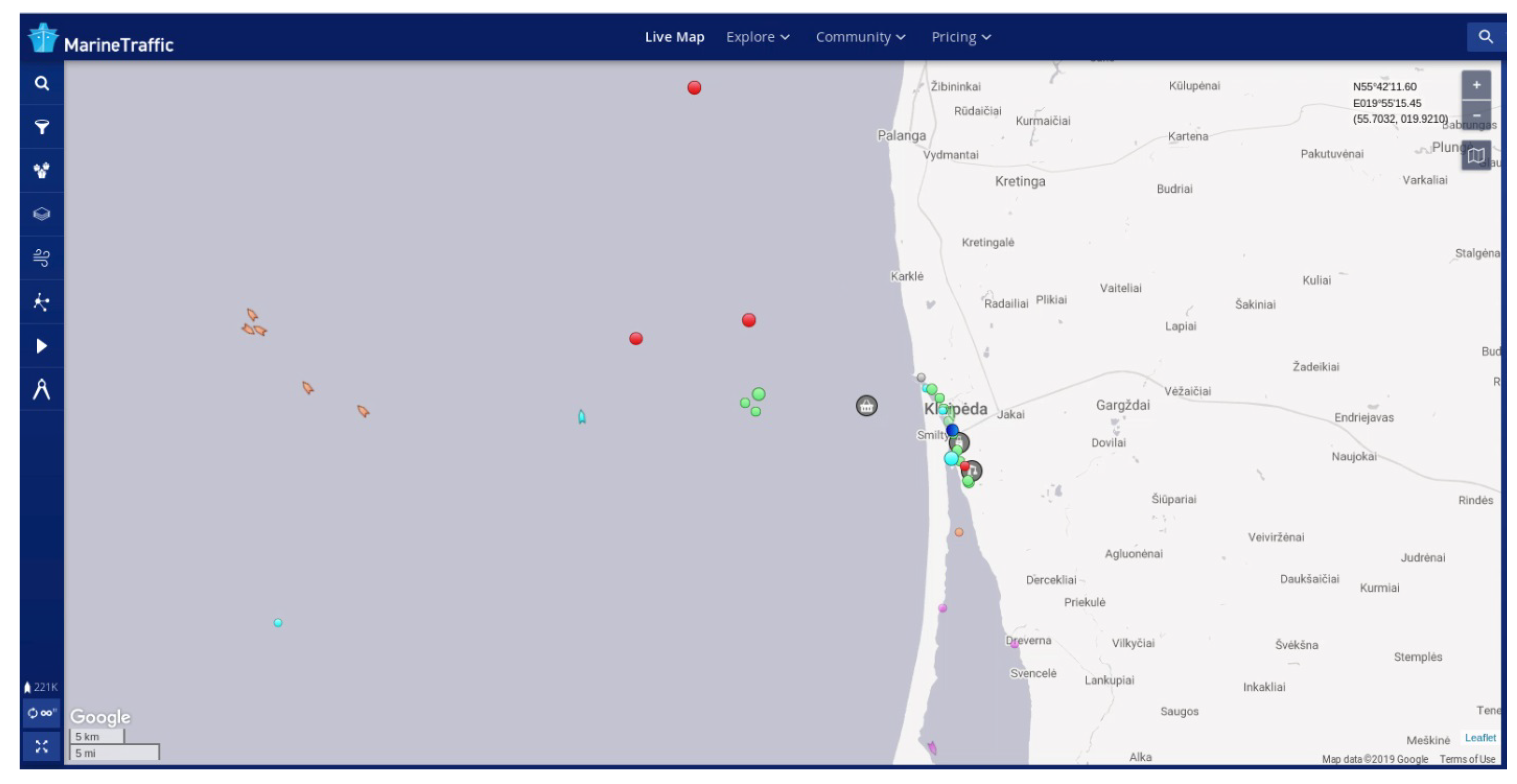
The flying site was chosen on the seashore in Klaipėda (Lithuania) near the seaport. This site provides acceptable safety and a good field of view into sea’s direction. In the vicinity of the seaport there are industrial and urban areas from where potential interference may originate. Additional marine traffic data was monitored by the Marine Traffic website as presented in
Figure 9.
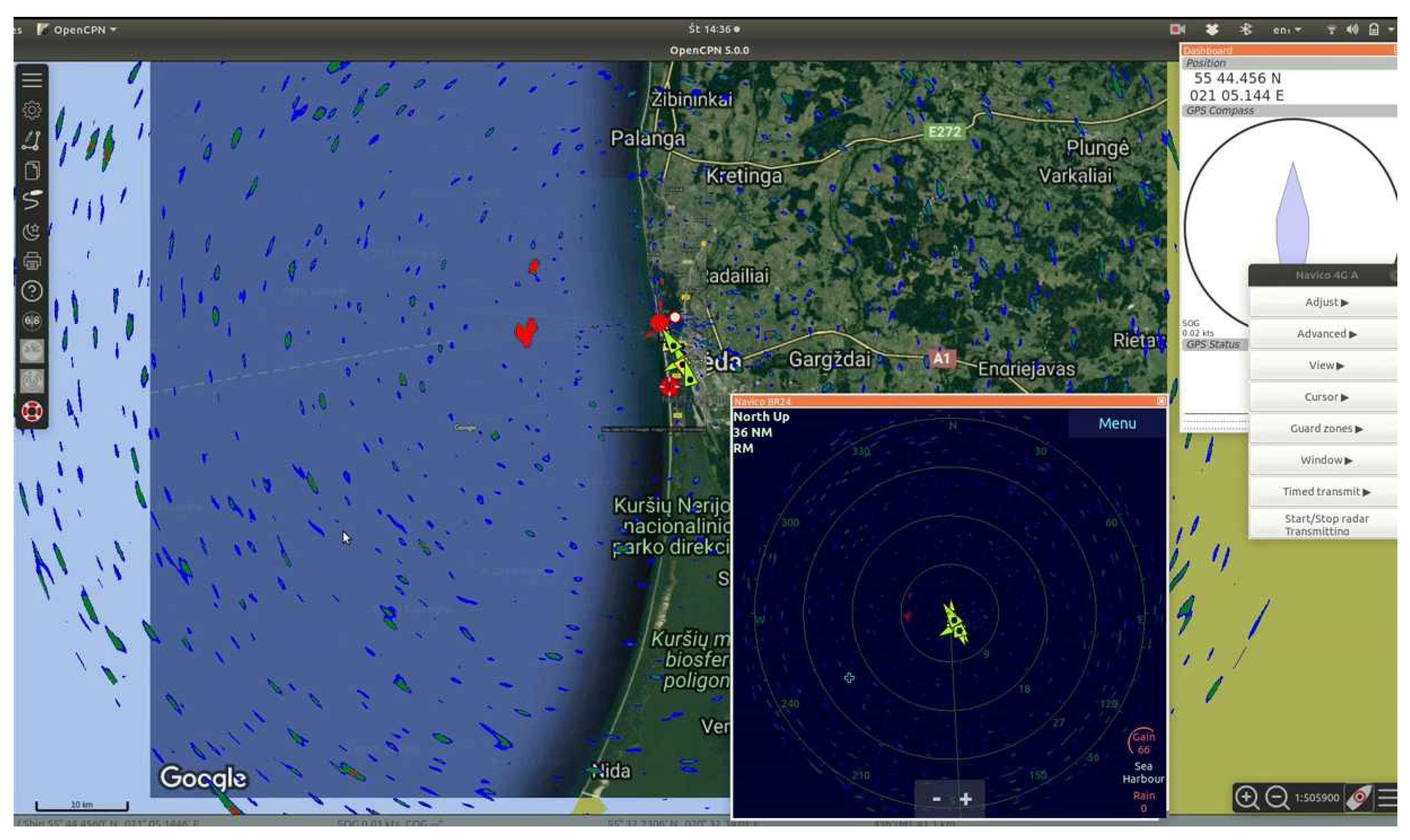
The first radar image and the AIS vessel positions (
Figure 10) were taken when the UAV was on the ground (on the roof of the car). The dark blue insert in the centre is generated using open CPN software. Red objects are the primary radar’s responses, green triangles are vessel positions, received from the Secondary radar (AIS). Positions of vessels correspond to positions presented in
Figure 10. Unfortunately, the only AIS data we have received were from the vessels in the port. As we find later, the short-range of the AIS receiving was caused by a frequency drift of the heterodyne of the cheap RTL SDR dongle receiver.
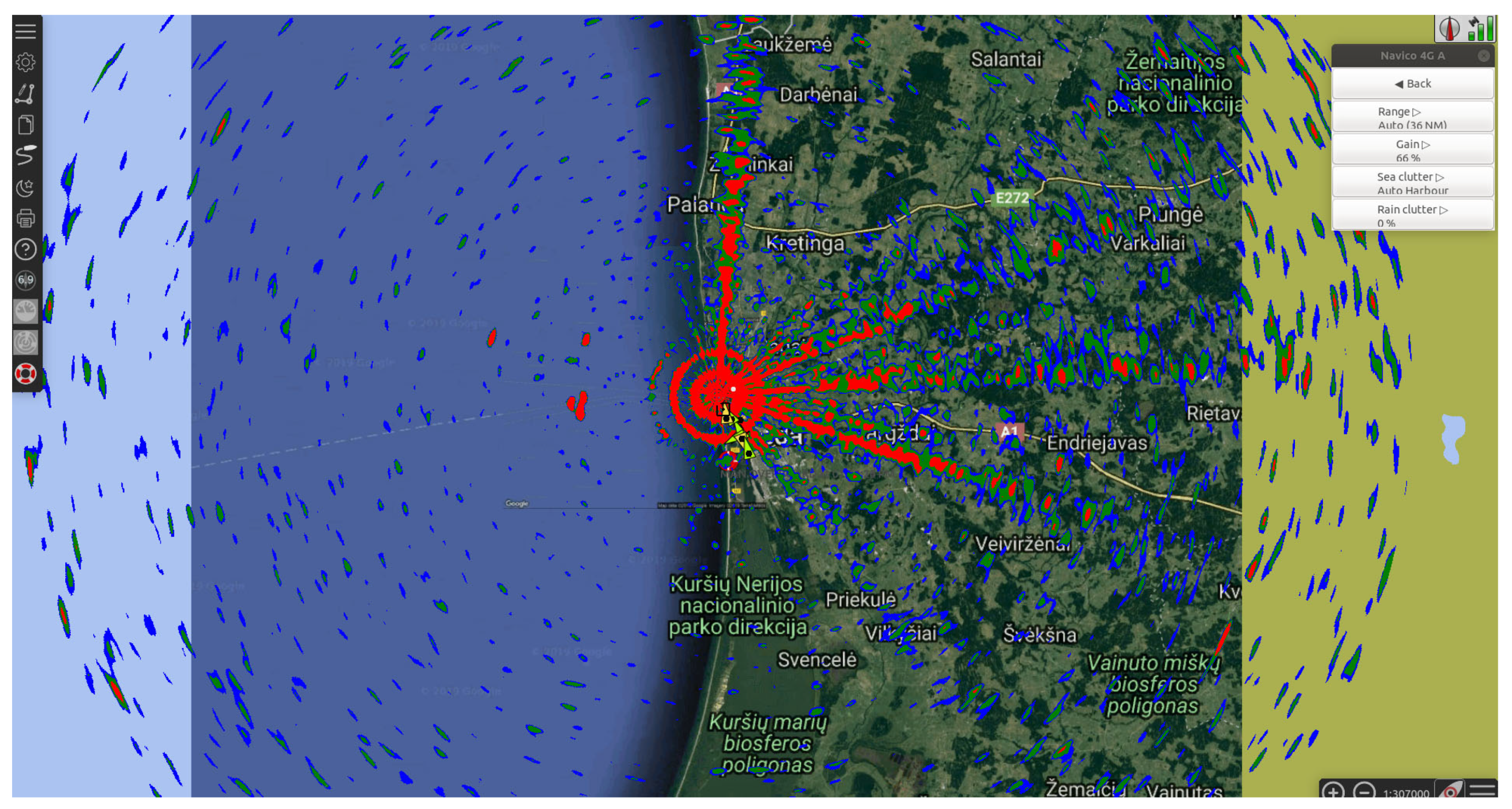
During takeoff, additional objects appeared on the radar’s response chart as presented in
Figure 11. These objects are not related to real targets but are radio interferences. Ray-like objects are typical interferences caused by signals on the radar’s frequency. Similar results are presented in [
23], where interferences to a meteoradar from Wi-Fi devices were obtained. The origin of the rays can be explained by the properties of the radar’s antenna. The highly directional rotating antenna can receive signals from directions very close to the antenna’s pointing direction. The frequency of the signals should be close to the radar’s operating frequency. The width of the rays depends on the antenna’s directivity. Due to rays being pointed in the direction of land, we can assume that this kind of interference is caused by land infrastructure of communication systems.
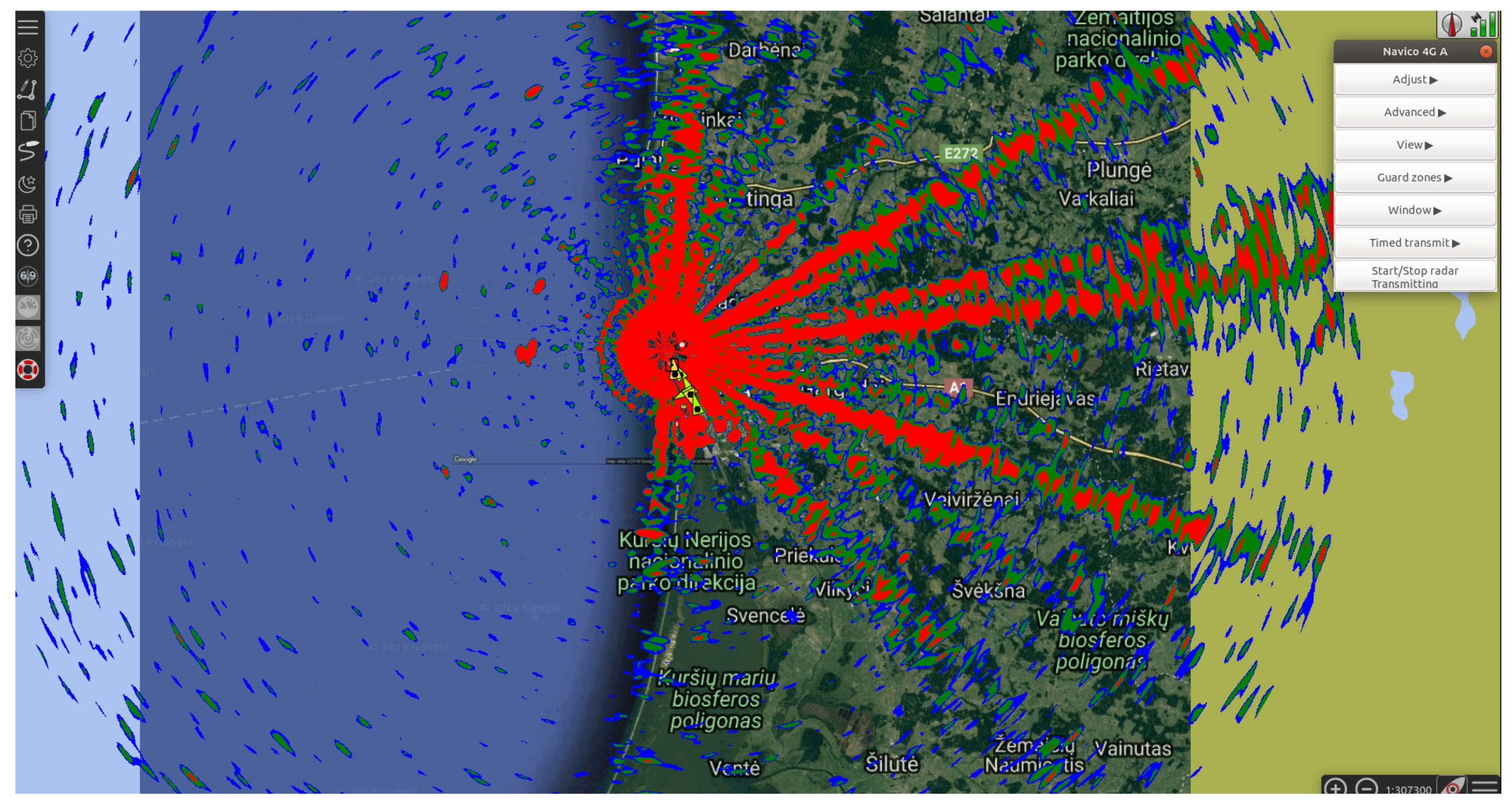
Another kind of interferences occurs as rings. The first ring appears at an altitude of approximately 15 m. The diameter of the ring is equivalent to 2280 m. At higher altitudes, rings with diameters two, three, and four times wider occur. The higher the altitude, the higher the intensity of the rings (
Figure 12). The distance to the target in the FMCW radar corresponds to a frequency, thus we can assume that the equal steps of the diameter of the rings in the image correspond to the harmonics of the interfering signal. It is obvious that the interference does not come through the antenna because the intensity of the interference’s image does not depend on the antenna’s pointing direction. This is a reason why we cannot estimate the direction to the source of the interfering signal. We can estimate the frequency of this signal
R when knowing the distance
R and parameters of the transmitted signal.
Here c0 is the speed of light, t is the delay time, f is the measured frequency difference of FMCW chirped pulse, F is the detector frequency, R is the distance between the antenna and the reflecting object, f/t is the frequency shift per time unit.
When the frequency chirp is linear,
f is equal to the frequency span,
t is equal to the pulse length. When the Simrad 4G™ radar is working in maximum range mode, the following values were measured:
f = 703 kHz,
t = 1.42 ms. The radius of the first ring (
Figure 12) is 2280 m.
We can calculate the frequency in the detector using the range Equation (
1). When the range
R is 2280 m, then the frequency
f is 7525 Hz. The distance of 1 km corresponds to 3.3 kHz on the frequency scale.
To estimate the Simrad 4G™ radar’s sensitivity to interferences and to estimate the interferences from various electronic equipment we have assembled the simplest measurement setup in the laboratory as presented in
Figure 13.
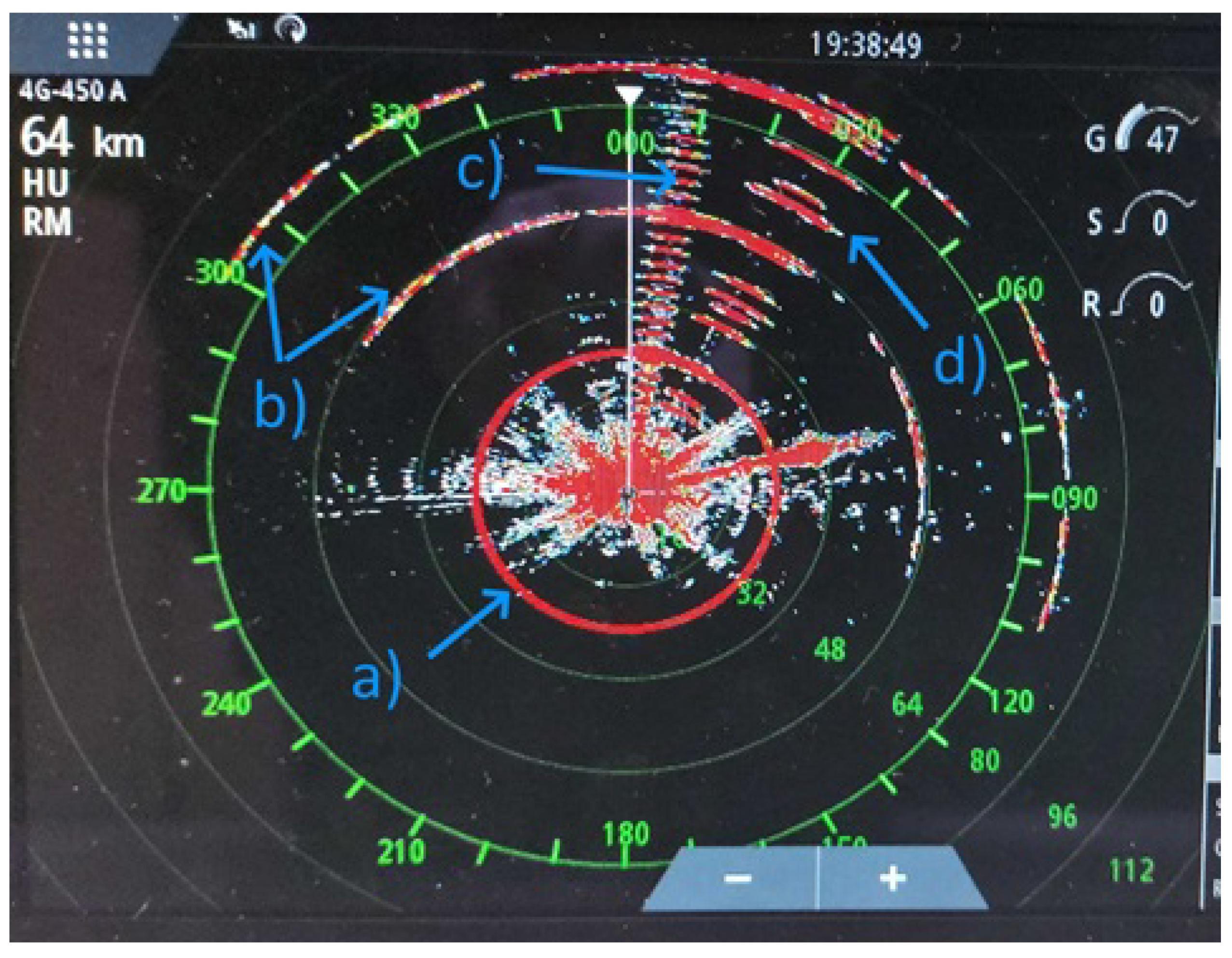
The test setup consists of the FMCW radar (a), a plotter (c), a switching power supply (e), and a low-frequency signal generator (d). A signal from the generator goes to the coil (g) (Loop antenna of an AM receiver), which is stuck to radar’s transmitter/receiver module (b). The distance from the generator and power supply to the radar was 1 m. The radar’s response to the plotter is presented in the
Figure 14.
The circle (a) represents a signal of 78 kHz 0.3 V from the generator, inducted to the receiver by a coil through an aluminum fixture. According to (1) and measured parameters of the transmitted signal, the range must be 23.6 km, which is what we see on the chart. The arc-like response (b) are the second and third harmonics of 78 kHz. The ray-like response (d) is generated by the power supply in X-band. The power supply is made of a mixture of plastics and is transparent for microwaves. The ray-like response (c) is produced by low-frequency electronic circuits (
Figure 13d). Despite the low-frequency generator being in a metal case, the air vents in the covers are implemented as slotted arrays. The length of the slots is about the half the length of a wave in X-band. Thus, the covers of the case can be transparent for the signals in this band with proper polarization. The vertical slots are transparent for horizontal polarization as our radar receives. When we rotate (slots become horizontal) the generator by 90 degrees the response (c) disappears.
5. Results of the Secondary Radar
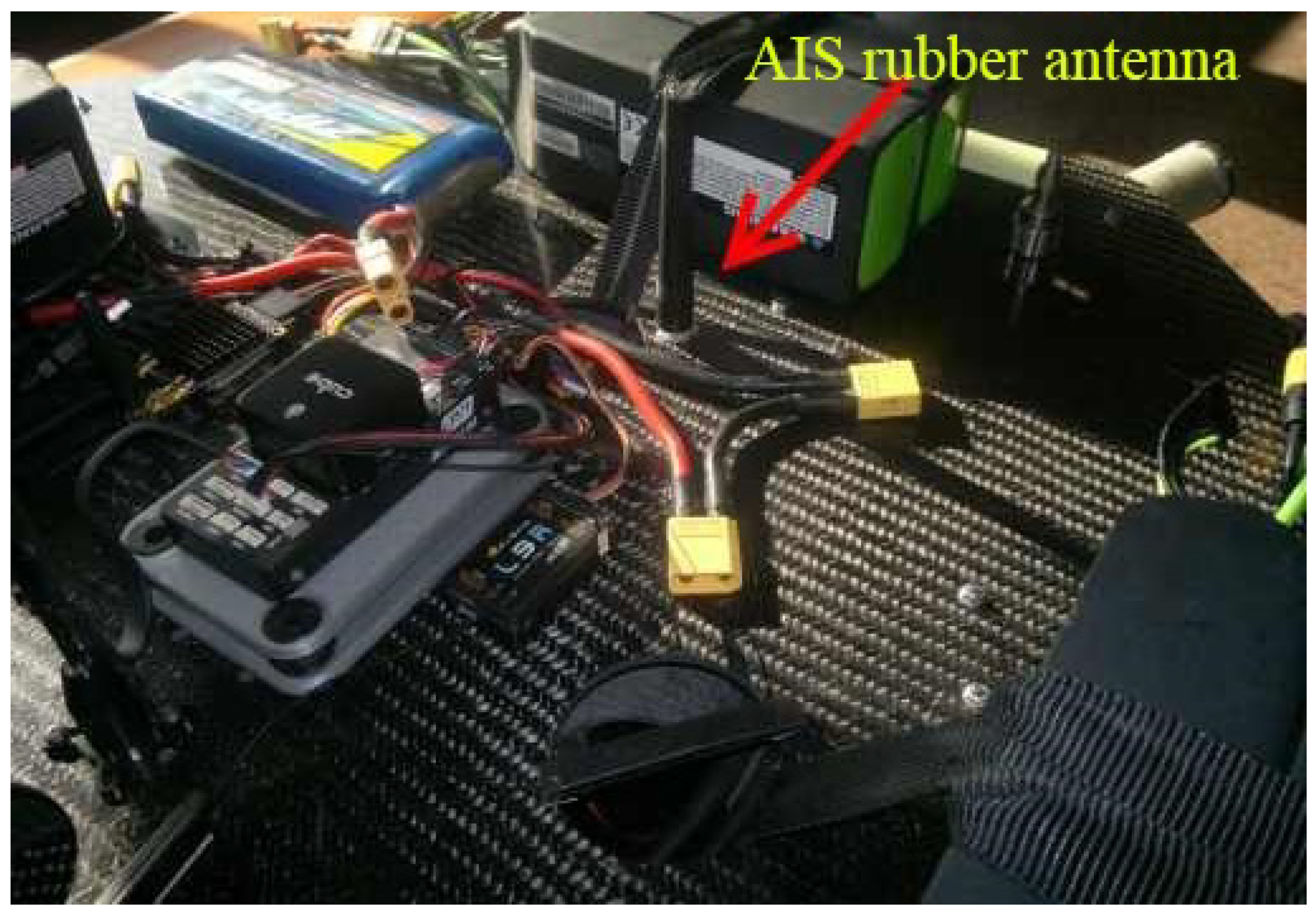
The term of secondary radar usually means equipment or a system, which allows to determine the positions of targets by receiving information transmitted from the targets. Examples of secondary radars are the AIS in maritime and the ADS-B system in aviation. Due to low weight, low cost, and possibility to integrate into OpenCPN software, the RTL-SDR dongle was chosen as the AIS receiver. It is a multipurpose SDR receiver not optimized for AIS reception. We used an electrically short (10 cm long) rubber antenna from a VHF hand-held radio station. The antenna was installed as presented in
Figure 15.
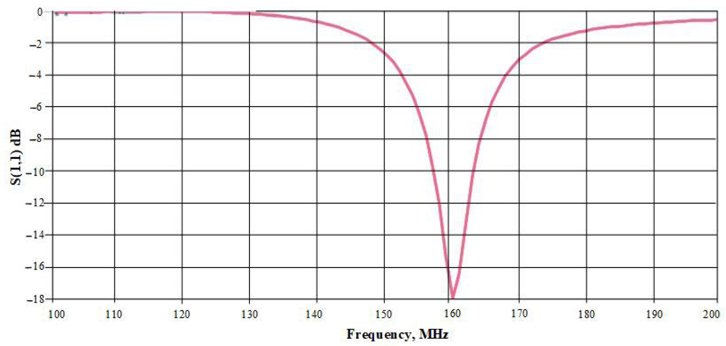
Despite the fact that the rubber antenna was well tuned to the AIS frequency when reflection loss was less than
dB (
Figure 16), we have noticed that the signal level with this antenna was more than
dB lower in comparison to conventional half wave dipole antennas. Those losses were caused by the lower efficiency of electrically small antennas and by the scattering of waves caused by surrounding equipment. For further experiments full-sized antennas (quarter wave monopole and half wave dipole) were chosen.
Due to the presence of high currents of frequencies in the order of kilohertz, the probability of interferences in radio frequency is significant. Interferences can penetrate the receiver via power supplying chains or via antenna input.
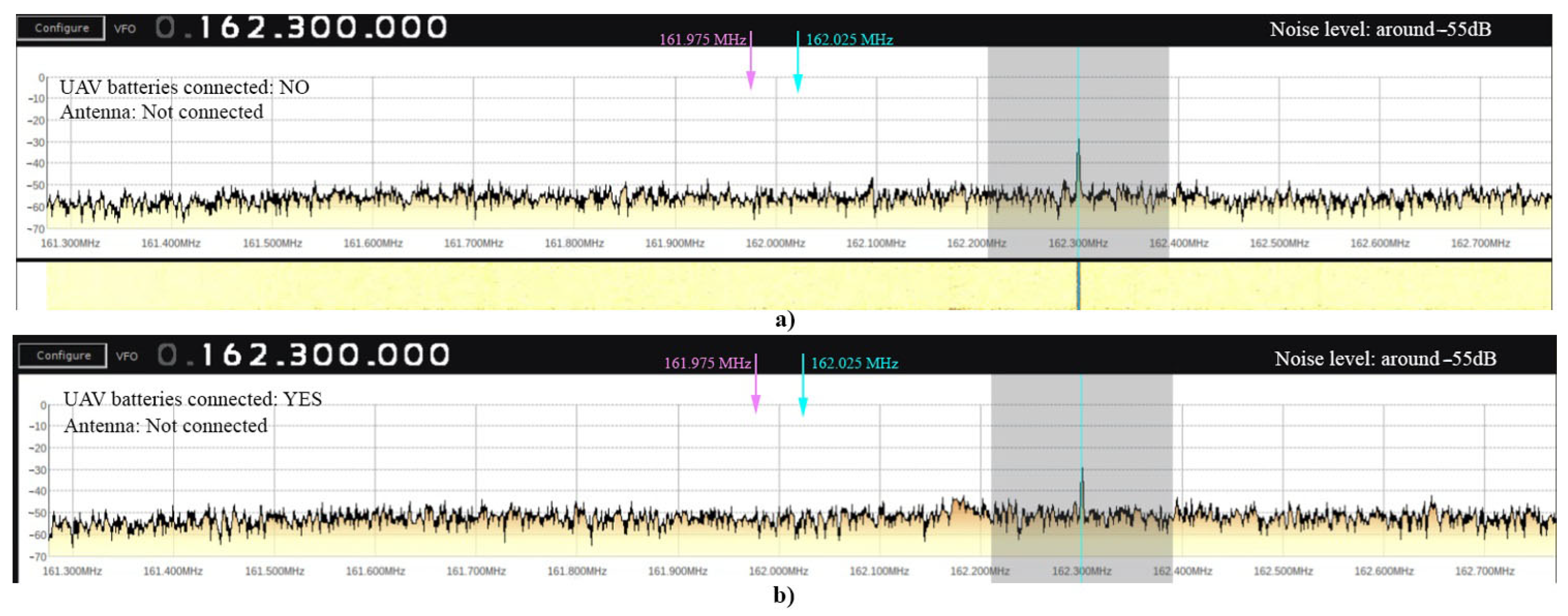
At first we measured the interference level via power supply chains when the antenna was disconnected from the receiver. We used the SDR open source software to monitor signal levels around the AIS frequencies. No significant interferences were obtained in this case, as presented in
Figure 17. The pink and blue arrows are at AIS frequencies. The peak on the right side corresponds to the tuning frequency of SDR receiver.
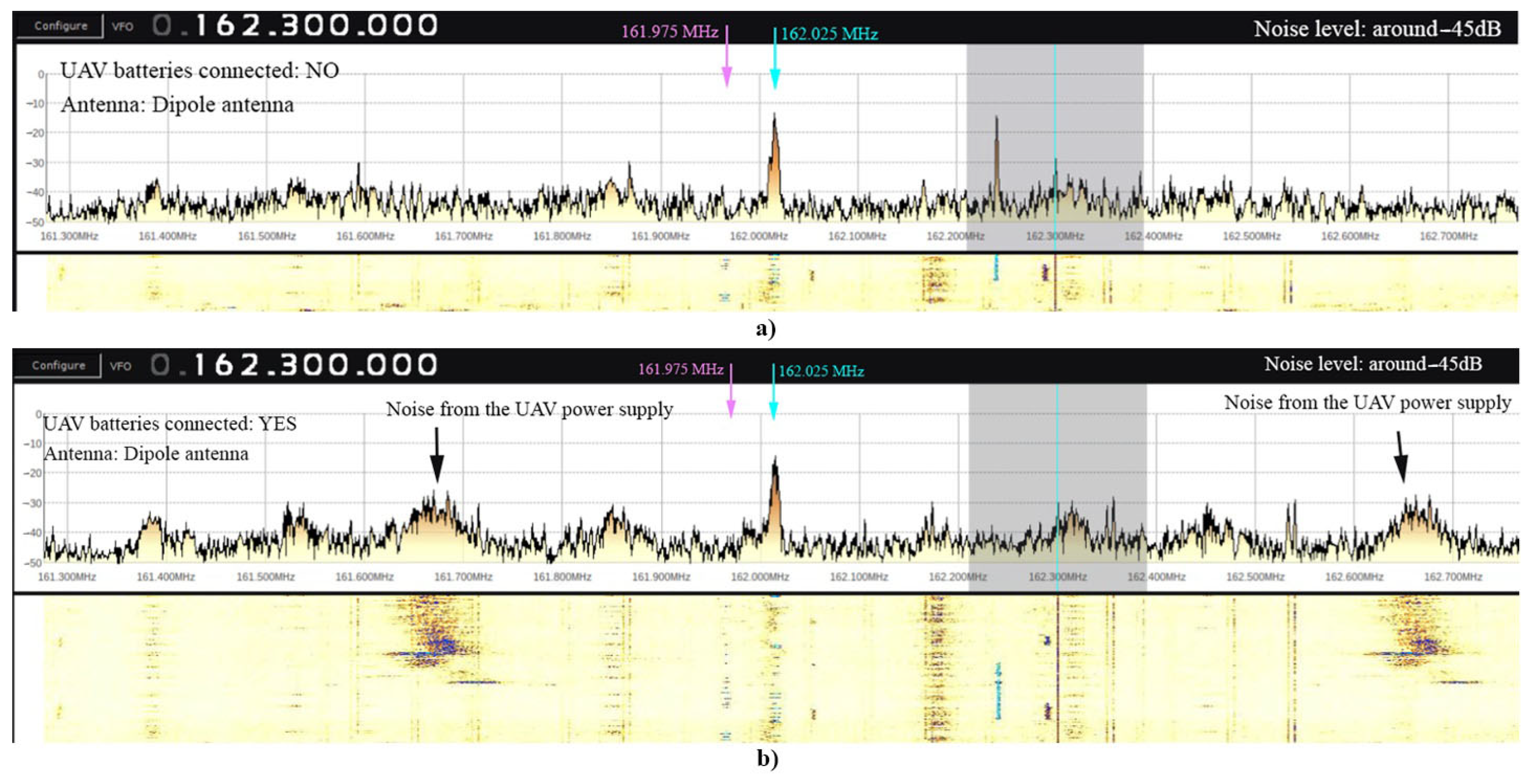
During the second step, we measured the interferences caused by the drone’s electric systems when the antenna was connected. We connected a quarter wave wire whip antenna instead of a rubber antenna. As presented in
Figure 18a, we can see that the noise level increased by 25 dB in comparison to when the antenna was disconnected. After connecting drone battery, two strong and wide interference peaks on 161.65 MHz and 162.65 MHz appear (
Figure 18b). Fortunately, those peaks are not on the AIS frequencies.
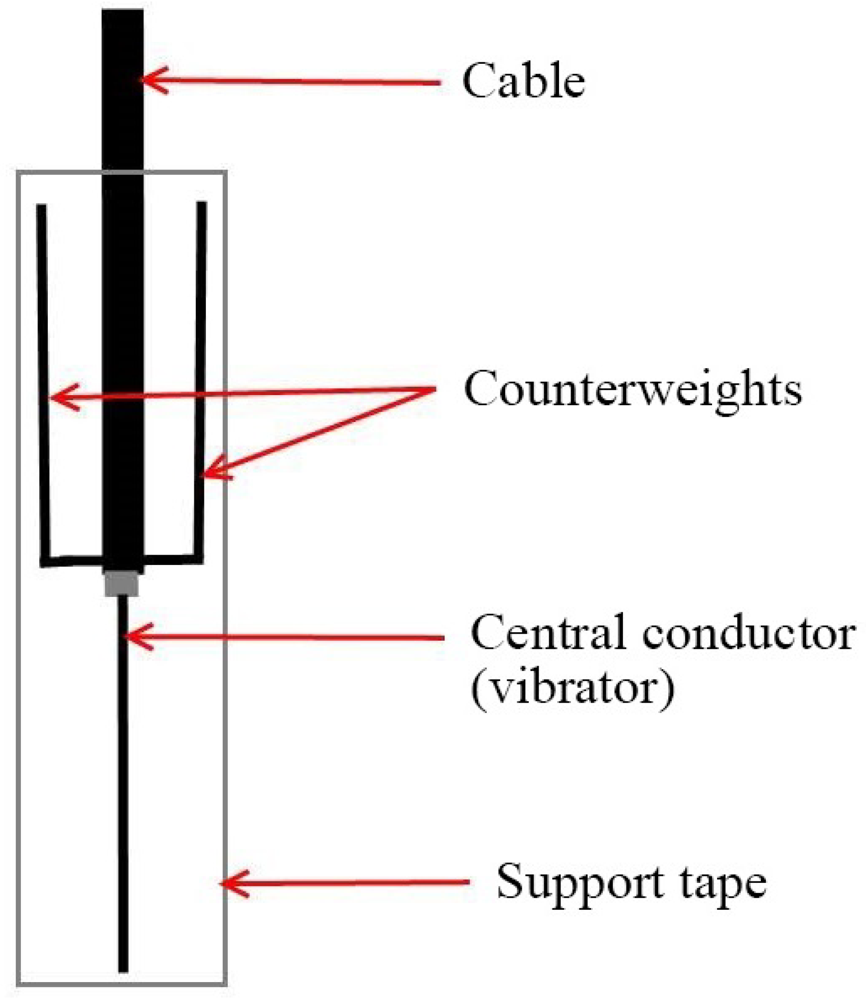
In order to reduce interference caused by the drone’s electric system, taking into account the recommendations in [
24] we have made a dipole antenna—a quarter-wavelength choke-sleeve antenna—as presented in
Figure 19. The lengths of the vibrator and the counterweights are equal to the quarter wavelength—462.5 mm for 162 MHz. The whole antenna’s structure, which consists of a cable, counterweights and a vibrator was arranged between two ribbons of 50 mm width of armed adhesive tape. The antenna was hung approx. 1 m below the bottom of the drone. The vertically arranged dipole antenna provides minimal amounts of radiation with patterns in axial directions. Due to this radiation property and increased distance from the targets to the drone we can expect a lower level of interference caused by the drone.
As presented in
Figure 20, we obtained a significantly lower level of interference in comparison to the monopole antenna.
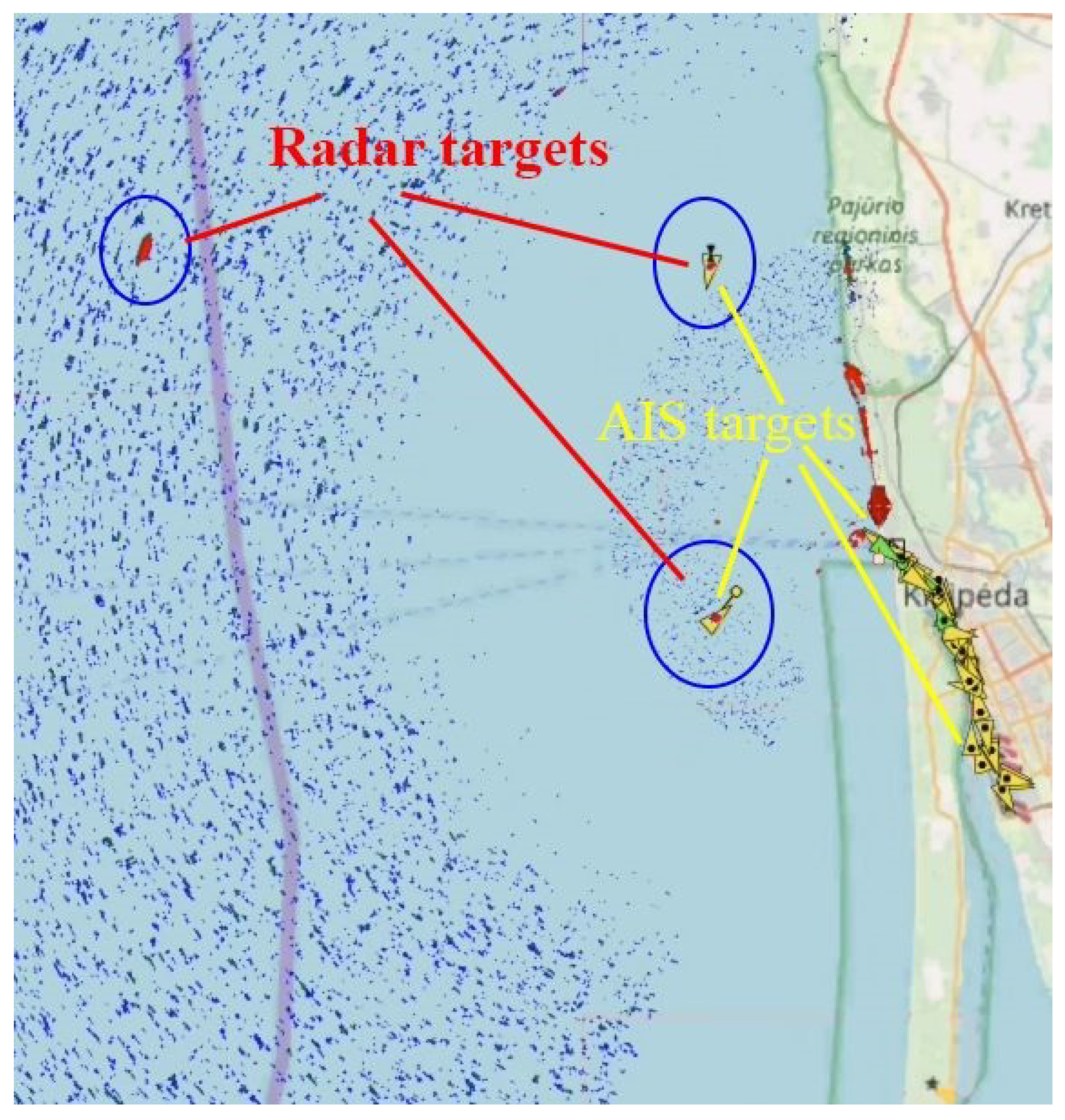
As was mentioned above, one of the possible reasons why vessels in the open sea were invisible by AIS was the frequency drift of the reference oscillator. This issue was fixed in the second experiment, during which the pulse compression solid-state radar was lifted into low altitude. The SDR receiver was replaced with one with a more stable oscillator. During this experiment we obtained AIS targets at a greater range and the number of targets increased several times as presented in
Figure 21.
Additionally, we created and investigated a large 2 m length antenna array using the drone when wind speed was up to 15 m/s. Maximal altitude was limited to 7 m. During the trials, only a few vessels were in the nearest sea area. Thus, the diversity of the detected targets was not great. Due to wider antenna dimensions, the angular resolution of the radar was increased 4 times. Radar scanning was implemented by rotating the drone’s antenna while the drone stayed in place. We did not observe radio frequency interferences when used this radar. Due to the lower weight and single antenna, this radar is attractive for UAV’s applications.
6. Discussion
Even though we reproduced both kinds of interferences in the laboratory, the origin and penetration of the circle-like interferences during the flight test is not fully clear. It is obvious that it penetrates not through the antenna. We know that the isolation of the power supply chains is sufficient. There was no response from the switching power supply. The amplitude of the supply voltage pulsations was 0.1 V, the frequency—50 kHz. The frequency of 50 kHz corresponds to the 15 km distance, though no circles of this range were obtained. The possibility of the induction signal with the frequency of 7.5 kHz being caused by UAV’s PWM circuit is not plausible because the frequency (radius) of the circles stays constant during various stages of flight. Because the intensity depends on altitude, there is no correlation to the load on the motors.
A possible origin of the circle-like responses could be the interfering radio signal penetrating the IF circuits or low-frequency induction affecting the wiring of the UAV. Low-frequency currents in the wiring may occur due to non-linear effects (such as inter-modulation or frequency conversion) in semiconductors when two or more high power radio signals affect the circuits.
No correlation between the apparent rings and the frequency of the rotors or their harmonics was observed, thus the possibility of the rotors causing additional reflections and/or Doppler shifts was ignored. No changes of the first ring’s radius during various stages of flight were observed, only the appearance of the additional rings due to the higher intensity of harmonics at higher altitudes.
The UAV’s radar has a rotating antenna inside its radome. It allows for rapid scanning at the cost of additional weight and volume of the rotator and circular radome. In this paper, the performance of the radar such as angular resolution and the range was prioritized over the speed, flight duration and range of the UAV. Using a relatively small UAV with a mass of several tens of kilograms the antenna diameter was limited to 0.5 m with an angular resolution of 5° due to weight. Initial experiments were performed using a 2 m long antenna on a rotorcraft UAV where scanning was done by rotating the aircraft. This concept can be implemented in a fixed-wing UAV, for which the antenna is integrated into the wing as presented in the patent application WO/2019/003194. [
25].
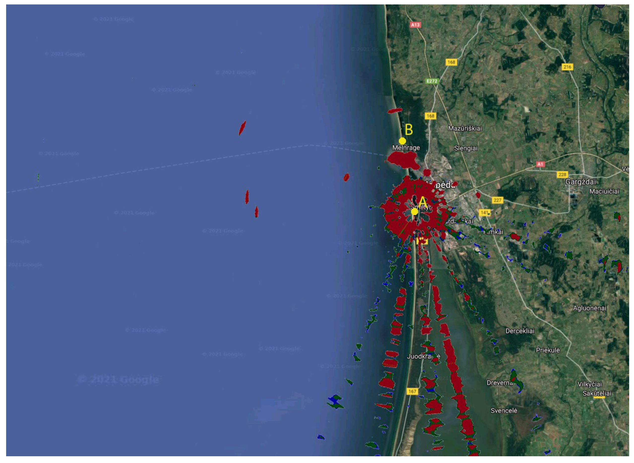
Additional experimentation and measurements were performed at A (
Figure 22), a new site, which was approximately 6 km from the previous measurement site B (
Figure 22). Measurements acquired at the new site show that the interferences are directed at a different angle towards the Curonian Spit. There were no interferences to the city of Klaipėda’s direction. The circular interferences were less significant and differed in frequency, which was 8.05 kHz (in the inner circle).
We can determine the source of interference, which was near the first measurement site, but travelling further the interferences were diminished. In this case, if the multi-rotor was to fly further away from the shore towards the sea, the circular interferences should decrease significantly.
7. Conclusions
The solid-state Simrad 4G™ FMCW marine radar was successfully installed under a low-cost custom-built octocopter UAV and elevated to an altitude of 120 m as a proof of concept. Increasing the altitude of the radar allows for a considerably wider radar range, both due to the altitude and the possibility of rapid change of the position. No interferences from the radar to the UAV and vice versa were observed, showing that such integration is suitable for daily applications. Two types of external interferences were observed:
Ray-type interferences caused by external radio signals, which were much stronger at higher altitudes.
Circle-type interferences caused by low frequency external signal penetration due to insufficient radio screening of the receiver.
The mentioned interferences may be corrected or avoided by applying detailed radio spectral analysis and adaptive filtration, though surveillance of the sea using UAVs with radars onboard is still possible despite mentioned interferences. The sources of both kinds of interferences affect the radar at ranges up to 6 km. Thus, during the missions over the sea the probability of interferences will be marginal.
The radar on the UAV can be used for the identification of vessels as a back-up option in case the AIS system fails. It can also be used for border control, anti-piracy measures, anti-drone systems, ice monitoring and in other applications.


 ,
, 